These assembly instructions are for the latest version of the CrossFire CNC. If you have CrossFire Machine Serial #15647 or before (located on your gantry tube), please follow the Legacy CrossFire Assembly Instructions.
CrossFire Assembly Guide
WARNING
Safety
When used correctly, the Langmuir Systems Crossfire CNC Plasma Table will offer you years of safe operation. However, like all other automated and industrial type machinery, there are important safety considerations and precautions that must be followed in order to avoid injury. Study these safety warnings carefully before assembling and using your machine.

ELECTRIC SHOCK
Electric shock can cause serious injury or death. This machine requires the use of high voltage electricity to operate. To avoid injury, always adhere to the following precautions:
- Never touch bare wires/buses/connections or components that are carrying electricity.
- Repair or replace all worn or damaged components. Turn off power to machine and plasma cutter when making repairs.
- Install and maintain equipment in accordance with the National Electric Code (NEC)
- If you have limited electrical knowledge/experience, hire a certified electrician to perform all electrical work.

FIRE AND EXPLOSION
Fire and explosion can be caused by the airborne sparks and slag igniting a nearby flammable material. Electrical fires can be caused if the machine is assembled or used incorrectly. To avoid injury, always adhere to the following precautions:
- Never operate the machine in the vicinity of flammable materials or where there is volatile and combustible fumes in the air.
- Do not use the machine to cut materials or parts that have previously contained fuel or flammable substance of any kind such as gas tanks.
- Always keep a fire extinguisher nearby in case of emergency.
- Never operate the machine in a poorly ventilated area.

AUTOMATIC OPERATION
The machine may operate at any time, automatically, and without warning. To avoid injury, always adhere to the following precautions:
- Acquire sufficient training before operating the machine.
- Never place any part of your body in direct contact with areas of the machine that can pinch and crush when powered on. Assume that if the machine is powered, it may move at any time.
- Keep area clear of bystanders, make sure that no one but the person operating the machine has access to the computer controls.

HAZARDOUS FUMES
Gases and fumes produced during the plasma cutting process can be hazardous to your health. To avoid injury, always adhere to the following precautions:
- Keep all fumes and gases from the area in which you breathe. Never operate the machine in an area with minimal or no ventilation. Use fans and blowers to remove fumes and gases from the work area.
- If ventilation is poor, use an air-supplied respirator system.
- The type of fumes and hazard level depends greatly on the type of metal being cut. Before cutting, consult the Material Data Safety Sheet (MSDS) for specific guidelines on the type and hazard level of the fumes produced during cutting.
- Never cut materials that has been coated with paint, oil, grease, or solvents.

ULTRAVIOLET AND INFRARED RADIATION
The plasma cutter produces high intensity ultraviolet and infrared light that can damage your eyes and skin. To avoid injury, always adhere to the following precautions:
- Never operate the machine without sufficient eye protection. Consult the user manual for your plasma cutter to determine the minimum protective shade required for the amperage of your machine. Alternatively, consult ANSI/ASC Z49.1.
- Wear gloves and suitable clothing to protect your skin at all times.
- Always alert bystanders before you begin cutting. Bystanders in the immediate vicinity must wear suitable eye and skin protection. Use welding screens whenever possible.

SPARKS AND AIRBORNE DEBRIS
Plasma cutting creates airborne sparks and debris that can cause eye injuries. To avoid injury, always adhere to the following precautions:
- Always wear suitable eye protection when operating the machine. Eye protection should follow the guidelines established in ANSI Z87.1.
- Ensure that all bystanders in the immediate vicinity are wearing suitable eye protection.

PINCH AND CRUSH POINTS
This machine can create pinch points while in motion during normal operations. To avoid injury, always adhere to the following precautions:
- Do not touch any part of the machine when it is moving under power.
- Be aware of all areas of the machine that could potentially be a pinching hazard, such as bearings, lead screws, lead nuts, and slides.
- Never make repairs to the machine when the machine is powered on.

HOT MATERIALS
The plasma cutting process uses extremely high temperatures to cut metal. As a result, the material can be very hot after cutting which can cause burns. To avoid injury, always adhere to the following precautions:
- Always assume that metal resting on the machine is hot enough to cause severe burns.
- Always allow the metal to sufficiently cool before handling. Use a bucket of water to cool down part before handling with bare hands.
- Never handle hot metal with bare hands. Use gloves or tongs to remove material from the machine.
WARNING
This product can expose you to chemicals which are known to the State of California to cause
cancer, birth defects or other reproductive harm. For more information go to www.P65Warnings.ca.gov.
Getting Started
1
Assemble Your CrossFire
Use the following CrossFire Assembly Guide to put together your machine.
2
Install Design Software
View the Software Workflow and follow along our Fusion 360 CAD and CAM guide to start designing parts!
3
Install FireControl
Use the FireControl Guide to Download and install the software used to control your CrossFire.
4
Run the Break-in Program
Download the CrossFire (FireControl) Break-in program from our Downloads page and run it using FireControl.
5
Make your First Cuts
Start cutting out parts with your CrossFire!
CrossFire Assembly
The Langmuir Systems CrossFire CNC ships partially assembled. Therefore, this section serves to provide all of the pertinent information and instructions needed to fully assemble your new machine.
Images in this Guide
The assembly drawings and pictures included in this guide can be expanded to full-screen and zoomed to provide more detail on a given step.
0: Unboxing
The CrossFire is delivered via standard (non-freight) delivery in one (1) box. The contents of the box are outlined below. All add ons and upgrades ship via their own packages.
CrossFire Box
- (1) Gantry Assembly
- (9) Steel Frame Tubes
- (2) Lead Screws
- (2) Slat Holders
- (10) Steel Slats
- (2) Stepper Motors
- (1) Electronics Enclosure
- (1) Hardware Box
- (1) Cable Support Tube
1: Install Casters
Materials
Parts
- (4) Leg Tube (with and without mounting holes)
- (4) Caster Insert
- (2) Caster with Lock
- (2) Caster without Lock
Hardware
- None
Tools
- Soft Faced Hammer or Mallet

Instructions
- Using a hammer, tap one Caster Insert into each of the four Leg Tubes. Note that the Caster Insert gets installed at the end that is opposite from the mounting holes.
- Identify the two legs that have 3 small holes (see supplemental diagram). In one, screw in a Caster With Lock. In the other, screw in a Caster Without Lock.
- The other two legs should not have 3 small holes. In one, screw in a Caster With Lock. In the other, screw in a Caster Without Lock.
2: Frame Assembly
Frame Tube Coloring
This manual depicts and references black powdercoated frame tubes but you may have received grey powdercoated frame tubes. These parts are otherwise identical and will not affect the assembly or performance of the machine.
CrossFire XL
If you have the CrossFire XL Kit, please assemble using XL Lower Rail. Please take particular note of the hole locations you will be using for the XL lower rail in Step 1 of the XL Kit instructions.
Gather frame tubes on a large work surface and assemble the frame of the CrossFire CNC.
Materials
Parts
- (2) Leg Tube (with electronics mounting holes)
- (2) Leg Tube (without mounting holes)
- (2) Lower Cross Tube (with Langmuir Systems and CrossFire printing)
- (2) Upper Cross Tube
- (1) Tool Holder Bracket, Shims, and T-Handle Wrench
Hardware
- (8) Bag 3 Hex Head Cap Screw, 3/8-16 X 4.5"
- (4) Bag 1 Hex Head Cap Screw, 3/8-16 X 2.5"
- (12) Bag 10 Hex Nut, 0.375”
- (3) Bag 12 Washer, 0.375”
- (20) Bag [Tube Spacers] Tube Spacer
Tools
- 9/16" Wrench
- Ratchet with 9/16" Socket


Instructions
- On a solid surface, place the Lower Cross Tubes parallel to each other with the logos facing up and out.
- Using the hardware shown in this diagram and in the subsequent diagrams, attach the Lower Rail Tube and Upper Cross Tubes to the two Lower Cross Tubes. Before fully tightening the bolts, use a framing square or protractor to roughly make the frame square. Then fully tighten the bolts.
- Attach each of the leg assemblies using the hardware shown (Be sure to also attach the Tool Holder Bracket, Shims, and T Handle Wrench on the front right corner as shown). Snug all of the leg mounting bolts down before tightening. Once all are snug down, go back and fully tighten them.
- Pick up the frame assembly and place it on the ground so that it is supported by the legs. Make adjustments to the casters as needed to prevent rocking.
3: Install Slat Holders & Slats
CrossFire Water Table
If you have a CrossFire Water Table, please proceed with installation of the water table at this point in assembly. If you have not received your water table, you can also easily install this at a later time.
Materials
Parts
- (1) Slat Holder
Hardware
- (4) Bag 7 Socket Head Cap Screw, 8-32 x 0.5"
- (4) Bag 16 Sheet Metal Screw, #8 x 0.75"
- (4) Bag 11 Hex Nut, Nylock, 8-32
- (4) Bag 14 Washer, #8
- (2) Bag 18 Slat Holder Bracket
Tools
- 9/64" Hex Key
- 11/32" Wrench
- Drill Gun with 1/4” socket or flathead screwdriver

Instructions
- Attach one Bag 18 Slat Holder Bracket to the Lower Rail Tube as shown using the Bag 16 Sheet Metal Screws. Secure the other Slat Holder Bracket to the Upper Cross Tube in the same fashion. Note: there are pre-drilled holes for the sheet metal screws to insert.
- Attach the Slat Holder to the previously installed Slat Holder Brackets using the hardware shown. Tighten screws fully.
Materials
Parts
- (2) Slat Holder
- (10) Slat
Hardware
- (8) Bag 16 Sheet Metal Screw, #8 x 3/4"
Tools
- Drill Gun with 1/4” socket or flathead screwdriver
- Mallet

Instructions
- Attach one Slat holder to one of the Lower Cross Tubes using the Bag 16 sheet metal screws. Repeat for the other side. Note that there are pre-drilled holes for the sheet metal screws to insert.

Instructions
- Insert Slats into each of the slots in the Slat Holders.
- If necessary, use a mallet to tap the slats down to fully seat them.
4: Y-Axis Rail & Gantry Installation
CrossFire XL
If you have the CrossFire XL Kit, please assemble using XL Y-Axis Rail. Please see Step 3 of the XL Kit instructions.
Materials
Parts
- (1) Y-Axis Rail
- (2) Stanchion Plate
- (1) Gantry Assembly
Hardware
- (4 per side) Bag 2 Hex Head Cap Screw, 3/8"-16 X 3"
- (8 per side) Bag 12 3/8" Washer
- (4 per side) Bag 10 Hex Nut, 3/8"
Tools
- (2) 9/16" Wrench

Instructions
- Attach the Y-Axis Rail to the machine frame using the Stanchion Plates and hardware shown. Pay careful attention to the orientation of the Y-Axis Rail. Do not tighten the hardware at this time.

Instructions
- Slide the Gantry Assembly onto the free end of the Y Axis Rail until contact is made with the previously installed Stanchion Plates.

Instructions
- Using the hardware shown, attach the Stanchion Plates to the Y-Axis Rail and Lower Rail Tube.
- Tighten all of the stanchion plate bolts including the ones that were installed in the previous step.
5: Z-Axis Slide Installation
Materials
Parts
- (1) Torch Mount
- (1) Fixed V-Block
- (1) Floating V-Block
Hardware
- (1) Bag 4 Socket Head Cap Screw, 10-24 x 0.5"
- (2) Bag 9 Socket Head Cap Screw, 1⁄4-20 x 1.5"
Tools
- 3/16" Hex Key
- 5/32" Hex Key

Instructions
- Secure the Fixed V-Block to the Torch Mount with a Bag 4 Socket Head Cap Screw. Fully tighten.
- Attach the Floating V-Block to the Fixed V-Block with Bag 9 Socket Head Cap Screws. Screw the bolts in a few turns each.
- Clamp the Torch Mount Assembly to the X-Axis Carriage using the thumb screw.
6: Gantry Alignment
Materials
Parts
- Partially Assembled Machine
Hardware
- None
Tools
- 3/16" Hex Key
- 7/16" Wrench
Instructions
- Watch video and follow instructions. Note: Machine coloration may be different than what you have received.
7: Install X and Y Lead Nuts
Materials
Parts
- (1) X-Axis Lead Nut
Hardware
- (4) Bag 8 Socket Head Cap Screw, #8-32 X 3/4"
- (8) Bag 14 #8 Washer
- (4) Bag 11 Lock Nut, #8-32
Tools
- 9/64" Hex Key
- 11/32" Wrench
- (2) 9/16" Wrench

Instructions
- Secure the X-Axis Lead Nut to the X Axis Carriage using the fasteners shown. Do not fully tighten the screws; the X-Axis Lead Nut must be able to float in all directions for alignment in a later step.
Materials
Parts
- (1) Y-Axis Lead Nut
Hardware
- (4) Bag 8 Socket Head Cap Screw, #8-32 X 3/4"
- (8) Bag 14 #8 Washer
- (4) Bag 11 Lock Nut, #8-32
Tools
- 9/64" Hex Key
- 11/32" Wrench

Instructions
- Secure the Y-Axis Lead Nut to the Y-Axis Carriage using the fasteners shown. Do not fully tighten the screws; the Y-Axis Lead Nut must be able to float in all directions for alignment in a later step.
8: Install Bearing Mounts
Materials
Parts
- (1) Y-Axis Lead Screw Bearing Mount
Hardware
- (2) Bag 7 Socket Head Cap Screw, 8-32 X 0.5"
- (2) Bag 5 Socket Head Cap Screw, 1/4-20 X 0.75"
- (1) Bag 17 608 Ball Bearing
Tools
- 9/64" Hex Key
- 3/16" Hex Key

Instructions
- Insert the Bag 17 Ball Bearing into the counterbore of the Y-Axis Lead Screw Bearing Mount. Install the two Bag 7 Socket Head Cap Screws to retain the bearing in the counterbore and tighten fully. Note: a C-clamp may be needed to insert the bearing into the bearing mount if a press-fit condition exists.
- Secure the Y-Axis Lead Screw Bearing Mount to the Y-Axis Rail using the two Bag 7 Socket Head Cap Screws and hand tighten only. NOTE: the screws have to be inserted through the mounting holes inside of the Y Axis Rail Tube. Temporarily removing the 3⁄8” Stanchion Plate bolt makes it easier to install the screws. Replace the 3⁄8” stanchion plate bolt when complete.
Materials
Parts
- (1) X-Axis Lead Screw Bearing Mount (pre-installed)
Hardware
- (2) Bag 7 Socket Head Cap Screw, 8-32 X 0.5"
- (1) Bag 17 608 Ball Bearing
Tools
- 9/64" Hex Key
- 3/16" Hex Key

Instructions
- Insert the Bag 17 Ball Bearing into the counterbore of the X-Axis Lead Screw Bearing Mount. Install the two Bag 7 Socket Head Cap Screws to retain the bearing in the counterbore and tighten fully. Note: a C-clamp may be needed to insert the bearing into the bearing mount if a press fit condition exists.
9: Install Lead Screws
Materials
Parts
- (1) Y-Axis Motor Mount
Hardware
- (2) Bag 5 Socket Head Cap Screw, 1/4-20 X 0.75"
Tools
- 3/16" Hex Key
- (2) 9/16" Wrench

Instructions
- Secure the Y-Axis Motor Mount to the Y-Axis Rail using the Bag 5 Socket Head Cap Screws and hand tighten only. NOTE: the screws have to be inserted through the mounting holes inside of the Y Axis Rail Tube. Temporarily removing the 3⁄8” Stanchion Plate bolts makes it easier to install the screws. Replace the 3⁄8” Stanchion Plate bolt when complete.
CrossFire XL
If you have the CrossFire XL Kit, please assemble using XL Y-Axis Lead Screw. See step Step 3 of the XL Kit instructions.
Materials
Parts
- (1) Y-Axis Lead Screw (longer of the two provided)
Hardware
- (1) Bag 6 Socket Head Cap Screw, 10-32 X 0.375"
- (1) Bag 13 #10 Washer
Tools
- 5/32" Hex Key

WARNING
It is critical that you pull back on the white compression collar while screwing into the lead nut. If this is not done, the lead nut can break.
Instructions
- Starting with the end that has the tapped hole, pass the Y-Axis Lead Screw through the Y-Axis Motor Mount and screw it into the lead nut.
- Continue screwing the Y-Axis Lead Screw into the Lead Nut until the end can be inserted into the Ball Bearing.
- Secure the end of the Y-Axis Lead Screw to the Ball Bearing using the Bag 6 Socket Head Cap Screw and Bag 13 Washer and fully tighten.
Materials
Parts
- (1) X-Axis Lead Screw (shorter of the two provided)
Hardware
- (1) Bag 6 Socket Head Cap Screw, 10-32 X 0.375"
- (1) Bag 13 #10 Washer
Tools
- 5/32" Hex Key

WARNING
It is critical that you pull back on the white compression collar while screwing into the lead nut. If this is not done, the lead nut can break.
Instructions
- Starting with the end that has the tapped hole, pass the X-Axis Lead Screw through the X-Axis Motor Mount and screw it into the lead nut.
- Continue screwing the X-Axis Lead Screw into the Lead Nut until the end can be inserted into the Ball Bearing.
- Secure the end of the X-Axis Lead Screw to the Ball Bearing using the Bag 6 Socket Head Cap Screw and Bag 13 Washer and fully tighten.
10: Install Stepper Motors
First, install the Y-Axis motor.
Couplers and Lead Screws
Note: the couplers and lead screws you have received may differ from those shown in these instructions.
If you received the set-screw style couplers, please follow the instructions shown on the sheet packaged with your machine or in the following image:

If you received Steel 4-Screw Clamp Couplers, please proceed with the instructions as written.
Materials
Parts
- (1) Y-Axis Motor
Hardware
- (1) Bag 19 Motor Coupler
- (4) Bag 4 Socket Head Cap Screw, 10-24 X 0.5"
Tools
- 5/32" Hex Key
- 3mm Hex Key
- 3/16" Hex Key

Instructions
- Slide the Bag 19 Motor Coupler onto the end of the Y-Axis Lead Screw until it rests against the shoulder.
- Secure the Y-Axis Motor to the Y-Axis Motor Mount using the fasteners shown and fully tighten. NOTE: The motor cable should be oriented downward.
- Do not tighten the Bag 19 Motor Coupler clamp at this step. They will be tightened in a later step.
- Tighten the screws that secure the Y-Axis Motor Mount and the Y-Axis Lead Screw Bearing Mount to the Y Axis Rail Tube.
Next, install the X-Axis motor.
Materials
Parts
- (1) X-Axis Motor
Hardware
- (1) Bag 19 Motor Coupler
- (4) Bag 4 Socket Head Cap Screw, 10-24 X 0.5"
Tools
- 5/32" Hex Key
- 3mm Hex Key
- 3/16" Hex Key

Instructions
- Slide the Bag 19 Motor Coupler onto the end of the X-Axis Lead Screw until it rests against the shoulder.
- Secure the X-Axis Motor to the X-Axis Motor Mount using the fasteners shown and fully tighten. NOTE: The motor cable should be oriented downward.
- Do not tighten the Bag 19 Motor Coupler clamp at this step. They will be tightened in a later step.
11: Install Electronics
Materials
Parts
- (1) Electronics Ecnslosure
- (1) Plastic Isolator
Hardware
- (3) Bag 16 Sheet Metal Screw, #8 X 0.75"
- (3) Bag 15 Washer, Plastic, #8
Tools
- Flathead screwdriver or 1⁄4 Socket Wrench

Instructions
- Remove the sheet metal screws that secure the Electronics Enclosure cover. Set them aside as they will be reused.
- Attach the Electronics Enclosure to the back left Leg Tube using the Bag 16 Sheet Metal Screws and Bag 15 Plastic Washers shown. NOTE: There are pre-drilled holes in the leg for the screws to be screwed into.
110V/220V Switch
If you are using the CrossFire or CrossFire PRO in a region with 220V power, be sure to flip the switch on the power supply to avoid damaging the power supply and other CrossFire electronics. It is set to 110V by default.

Ensure Installation of Replaceable Relay
While the electronics enclosure is open, make sure that the torch firing relay (marked in image below) is properly seated.

Materials
Parts
- (1) Electronics Enclosure Cover
Hardware
- (14) Previously Removed Sheet Metal Screws (#8 x 0.75")
Tools
- Flathead screwdriver or 1⁄4 Socket Wrench

Instructions
- Re-attach the Electronics Enclosure Cover.
12: Install Cable Support and Tube Caps
Materials
Parts
- (16) Tube Caps
- (1) Cable Support Tube
Hardware
- None
Tools
- Mallet

Instructions
- Using a mallet, insert Tube Caps into the open ends of each tube.
- Insert the Cable Support Tube into the hole in the Y-Axis Rail.
13: Connecting Electronics
In this section, we will finalize assembly of the CrossFire by plugging in the electronics components, routing cables, and tightening lead nuts.
-
Plug in X & Y Stepper Motors
Locate the DSUB connector for the X-axis stepper motor and insert into the corresponding socket on the Electronics Enclosure. Do the same for the Y stepper motor as shown in the image below. Be certain to fully tighten the two screw clamps on each DSUB connector into the Electronics Enclosure.
![]()
-
Plug in USB Cable & Power CableJogging Your Machine
In the following steps, we will need to jog the machine to the front right corner. To do this, we will need to use FireControl software to jog the machine. Please make sure that you have followed all of the steps in the FireControl User Guide section Connecting to a CrossFire Machine before proceeding to power on the machine for the first time.
Next plug in the USB Cable and Power Cord to the corresponding ports on the Electronics Enclosure. Plug the USB cable into your computer and switch on the power to the Electronics Enclosure.
![]()
-
Tighten the Motor Couplers
At this point, the Y-Axis and X-Axis Motor Couplers are installed but they are not yet tight. In this step, we will fully tighten all of the motor couplers using the procedure outlined in the following video. The electronics enclosure must be powered on so the motors have holding torque. Note: this applies to the 4-Screw steel couplers but the tighten-and-check procedure is relevant to the 2-Screw aluminum couplers as well. Caution: Excessive torque can cause the screws or hex key to strip.
Tightening Procedure
- Tighten the inside screws until they are snug.
- Tighten the outside screws until they are snug.
- Turn the inside screws an additional 1/8-1/4 turn.
- Turn the outside screws and additional 1/8-1/4 turn
- Grasp the lead screw and try to back drive the stepper motor. If it can be backdriven, the coupler is tight. If the coupler slips, repeat the previous two steps.
-
Tighten the X-axis and Y-axis Lead Nuts
At this point, the X-axis lead nut and both Y-axis lead nuts should be loose. Next, using FireControl we need to jog the machine to the most positive X position (right keyboard arrow key) and the most positive Y position (up keyboard arrow key). Once the Gantry is close to the stanchion plates in the Y direction, change the Jog Speed in FireControl to 50 IPM. Finally, jog the machine down in the Y direction (negative) by repeatedly tapping the jog key until the bearings in the gantry carriage make slight contact with the stanchion plate. This step is necessary to square the gantry to the slat bed. At this point, your machine should look like the image shown below.
![]()
Next, tighten the bolts on the X-axis lead nut as shown below. Your lead nut mounting tab should still be finger tight to the X-axis carriage.
![]()
Next, tighten the bolts holding the X-axis lead nut mounting tab to the X-axis carriage as shown below.
![]()
Finally, tighten the bolts on the Y-axis lead nut as shown below.
![]()
-
Install Plasma Cutter and Route Torch LeadMaterials
If you are running a Z-Axis kit with your CrossFire, be sure to allow enough slack in your plasma cutter torch lead to not put any lifting force onto the floating Z-Axis and IHS system. Failure to do so will cause errors generated by the IHS system.
Install your plasma cutter's torch into the torch mount and tighten the two stainless fasteners (4 stainless fasteners if using the Machine Torch Mount) to secure your torch. Be careful not to overtighten on the torch body or constrict the movement of internal components as this may lead to lost arc and misfires. The fit should be snug so that the torch doesnt spin in the mount.
Using the provided velcro straps, route your torch lead along the cable routing pole with enough slack to move around the entirety of the cutting surface.


CrossFire XL Kit
The following instructions describe the installation of the CrossFire XL kit on a base CrossFire CNC Machine.
0: Unboxing & Preparation

Your CrossFire XL Kit package will include the following items:
- XL Y-Axis Rail
- XL Lower Rail
- XL Y-Axis Lead Screw
- (3) Self-tapping Sheet Metal Screw
If you are installing the XL on a new machine, you can skip steps A1 and A2 below.

Instructions
-
Partially disassemble the machine until it matches the image shown. The
following items will not be re-used:
- Y-Axis Rail
- Y-Axis Lead Screw
- Lower Rail Tube
- Set all other items aside as they will be re-installed in later steps.
1: Install XL Lower Rail

Instructions
- The XL Lower Rail Tube has two sets of mounting holes that secure it to the machine frame. One set of holes is to be used if your machine does not have a Langmuir Systems supplied Z axis kit. The other set of holes is to be used if your machine does have a Langmuir Systems supplied Z-Axis Kit. Study the provided diagram and identify the mounting holes that are needed for mounting.
- Install the XL Y-Axis Lower Rail Tube [Step 2] as with the base machine.
Special Note
Use of the water table is highly encouraged with the XL kit since the larger cutting envelope increases the risk of warpage. However, if you do not have a water table, use the provided self-drilling and tapping sheet metal screws to secure the center sheet metal bracket to the XL Lower Rail.
2: Preload Upper Rail to Gantry

Instructions
- Break loose the socket head cap screws that secure each of the adjustable bearing blocks and then snug them down slightly. Unscrew the Bearing Block Preload Screw on each adjustable bearing block 2-3 turns.
- Check that each of the adjustable bearing blocks can shuttle back and forth. If they do not easily move, loosen the socket head cap screws until they do.

Instructions
- Slide the XL Y Axis Rail Tube into the Bearing Blocks in the orientation shown. The Rail should pass through easily since the adjustable bearing blocks should be loose from the previous step.
-
On each Adjustable Bearing Block, slowly turn the adjustment set screw
clockwise. Stop turning the set screw when the following conditions are met:
- Both Adjustable Bearing Block Bearings are in contact with the Y Axis Rail.
- At least one of the two opposing Fixed Bearing Block Bearings is in contact with the rail.
- Once Step 2 is complete, tighten the socket head cap screws that secure the Adjustable Bearing Block to the backing plate.
- Complete Step 2 and 3 for each of the four Adjustable Bearing Blocks that the machine has.
- Done successfully, the Y-Axis Rail should be able to shuttle back and forth relatively easily, but there should not be any clearance/lash between the Y-Axis Rail and the Gantry.
3: Install XL Upper Rail, Gantry, & Lead Screw

Instructions
- Re-install the Stanchion Plates onto the XL Lower Rail Tube [Step 4] as on the base machine.
- Lift the Gantry/Y Axis Rail Assembly onto the machine so that the Y Axis Rail rests between the stanchion plates. Reinstall the previously removed hardware to secure the Y axis Rail to the Stanchion Plates and tighten fully.
- If the X Axis Gantry Rail is not parallel to the Slat Bed, repeat the machine alignment [Step 6].

Instructions
- Break loose the four screws that secure the Y-Axis Lead Nut so that it can float.
- Re-Install the Lead Screw Bearing Mount [Step 8] as on the base machine.
- Re-Install the Y-Axis Motor Mount [Step 9] as on the base machine.
- Install the Y-Axis XL lead Screw [Step 9] as on the base machine.
- Re-install the Y-Axis Motor and Motor Coupler [Step 10] as on the base machine.
- Tighten the screws that secure the Y-Axis Motor Mount and the Y-Axis Lead Screw Bearing Mount.
- Re-install any Tube Caps that were previously removed.
- Re-install the Cable Support Tube.
- Under power, jog the gantry to the maximum extent of travel in the negative Y direction. At that position, re-tighten the screws that secure the Y-Axis Lead Nut. Jog the Y axis back and forth to ensure that there is no binding over the entire range of travel.
Z-Axis Upgrade Kit
Installation with XL Kit
If you currently have a CrossFire XL Kit installed with a Zinc Plated (silver color) lower rail, you will need to install the black XL Kit Lower Rail Tube that you received with the upgrade kit. Follow the XL Kit Installation instructions. Be sure to use the mounting holes necessary for the Z-Axis before continuing on.
If you currently have a CrossFire XL Kit installed with a Black Powder Coated lower rail, you will need to re-install your XL Kit Lower Rail Tube using the Z-Axis Mounting holes as described in the XL Kit Installation instructions before continuing on.
If you do not have an XL kit, continue on to the first step.
1: Remove the Electronics Enclosure
Your existing electronics enclosure will need to be removed to replace it with the latest version or to install the upgrade components. Remove your Electronics Enclosure from the leg of your CrossFire with a flathead screwdriver or ¼ Socket Wrench.
Instructions
- Ensure the Electronics Enclosure is powered off and the Power Supply cable is unplugged.
- Disconnect the X Motor cable, Y Motor cable, and Torch Fire Cable from the Electronics Enclosure.
- Remove the sheet metal screws that secure the Electronics Enclosure Cover.
- Remove the three screws that secure the Electronics Enclosure to the leg.
- Remove the Electronics Enclosure.
Gen 1 vs Gen 2 Electronics Enclosure
If you are upgrading a Gen 1 [Mach 3] CrossFire you will no longer need the Electronics Enclosure you removed and can now proceed with the new Gen 2 Electronics Enclosure included in your Upgrade Kit.
If you are installing the Z-Axis Upgrade on a Gen 2 [FireControl] CrossFire, proceed with the Electronics Enclosure you just removed.
2: Install Z-Axis Driver & THC
Next, you will be installing the Stepper Driver for the Z-Axis as well as the THC module into the Gen 2 Electronics.
Materials
Parts and Hardware
- (1) Z-Axis Driver
- (2) #4-40 X 5/16 SCREW
- (2) #4-40 HEX NUT
Tools
- Phillips Screwdriver
- ¼ Wrench
Instructions
- Remove the sheet metal screws that secure the Gen 2 Electronics Enclosure Cover if you haven't already. Set the screws and Cover aside.
- Install the Z-Axis Driver using the hardware provided. Identify the holes used to mount the Z-Axis Driver, pass a #4-40 X 5/16 Screw through the hole closest to the Z-Axis Motor Port and partially thread a nut onto the screw then slide the driver into place and tighten.
![]()
![]()
![]()
![]()
- Install the THC Module into its position on the Motion Control Board. Ensure the D13 Pin is oriented as shown.
![]()
![]()


3: Z-Axis Driver Connection
WARNING
Ensure sure the power supply cord has been removed before proceeding. Be sure to attach the correct wires into the correct terminals as failure to perform this step accurately could result in shock or failure of the electronics.
Materials
Parts and Hardware
- (1) Power Wiring Harness
Tools
- Phillips Screwdriver
Instructions
-
Find the Power Wiring Harness which was provided with the kit.
Attach the black DC(+) wire to the (+) terminal of the power supply.
Attach the white DC(-) wire to the (-) terminal of the power supply.
![]()
![]()
Insert green Terminal Block Connector at the other end of the Power Wiring Harness into the Driver port as shown.
![]()
![]()
-
Cut the zip tie that currently ties off the MCB Control Plug inside the Electronics Enclosure.
Insert the Green Terminal Block Connector into the Driver port as shown.
![]()
-
Insert the Green Terminal Block Connector of the Z Axis Motor Port Pigtail into the Driver port as shown.
![]()
![]()


You've now completed the installation of the Z-Axis Driver and THC Module.
4: Reinstall Electronics Enclosure

Materials
Parts and Hardware
- (3) Sheet Metal Screw, #8 X ¾
- (3) Washer, Plastic, #8
- (1) Plastic Isolator
Tools
- Flathead screwdriver or ¼ Socket Wrench
Instructions
- Attach the Upgraded Electronics Enclosure to the back left Leg Tube using the Sheet Metal Screws and Plastic Washers shown. NOTE: There are pre-drilled holes in the leg for the screws to be screwed into. Remember to install or re-install the Plastic Isolator between the leg and enclosure as shown.
- Re-attach the Electronics Enclosure Cover with previously removed screws.
5: Install Z-Axis Assembly

Materials
Parts and Hardware
- (1) Z-Axis Assembly
- (2) ¼-20 X ¾” Socket Head Cap Screws
Tools
- 3/16" Allen Key
Instructions
- Remove the Torch Mount, Torch Mount Clamp Strap, and associated hardware. Set these items aside as they will be re-used.
- Secure the Z-Axis Assembly to the X Axis Carriage using the ¼-20 x ¾ Socket Head Cap Screws provided in the kit.
- Re-install the Torch Mount using the hardware that was previously removed.
6: Install Cable Support Extension
This extension is important to keep your new Z-Axis motor and IHS cables supported.

Materials
Parts and Hardware
- (1) Cable Support Tube Extension
- Black Velcro Straps
Tools
- None
Instructions
- Insert the Cable Support Tube Extender over the Cable Support Tube.
- Pass the provided two black velcro straps through the holes in the cable support tube and the cable support tube extender.
7: IHS Connection
Next, you will be installing and securing the IHS Cable.
Materials
Parts and Hardware
- IHS Cable
- P-clamps
- Zip ties
- (4) #8 x ½” Self Drilling Sheet Metal Screws
Tools
- Phillips Screwdriver
- Screw/Impact Gun w/ ¼” bit
Instructions
-
Locate the Initial Height Sensing (IHS) cable. You will find that your Z-axis assembly ships
with two pre-installed wires that are connected to the IHS switch inside the Z-axis. Connect
the two blade connector ends of the IHS cable into the corresponding connectors on the Z-axis
assembly as shown below. Note: It is not important which wire is connected to the red or black
end of the IHS cable.
![]()
-
Remove the socket head cap screw and P-clamp on the back of the Z-axis assembly.
Affix the p-clamp around the IHS cable and re-attach to the Z-axis assembly using
the socket head cap screw as shown below. This p-clamp provides strain relief for the
IHS cable when the torch carriage moves around the plasma table.
![]()
-
Keeping slack in the IHS cable to match the Z-axis cable, use the provided
black zip ties to affix the IHS cable to the Z-axis cable as shown. Clip
the excess ends of the zip ties as necessary.
-
Undo each of the two black velcro straps on the Cable Support Tube in order
to affix both the IHS cable and Z-axis motor cable to the tube using these straps.
![]()
-
Next, locate the four black plastic P-clamps and the four #8 x ½” Self Drilling Sheet Metal Screws. With a screw gun,
use the P-clamps and fasteners to secure the Z stepper motor cable and the IHS cable to the underside of the Y-axis
frame tube toward the electronics enclosure.
![]()


8: Motor Connections
Next, you will be connecting your motors with cable extension and D-Sub screws.
Materials
Materials
Parts and Hardware
- D-Sub Extension Cable
- (6) D-Sub Replacement Screws
Tools
- Phillips Screwdriver
Instructions
- Remove the thumbscrews from the X-axis motor, the Y-axis motor, and the Z-axis motor.
- Use the D-sub replacement screws and a philips screwdriver to attach the X-axis motor and the Z-axis motor to their respective ports of the electronics enclosure.
-
Use the D-sub replacement screws and a philips screwdriver to attach the Y-axis motor to the D-sub extender.
Then, plug the D-sub extender into the Y-axis motor port of electronics enclosure and use the thumbscrews to attach it.
![]()
![]()
- Plug the provided power cable and USB cable into the electronics enclosure. Note: Gen 1 Upgrade customers MUST use the new provided USB cable.


10: Gantry Alignment and Break-in
Jogging Your Machine with FireControl
In the following step, we will need to jog your CrossFire machine. To do this, we will need to use FireControl to jog the machine. Please make sure that you have downloaded FireControl from our Downloads page and followed all of the steps in the FireControl User Guide section Connecting to a CrossFire Machine before proceeding.
Materials
Hardware
- None
Tools
- 3/16" Hex Key
- 7/16" Wrench
- Tape Measure
Instructions
- Follow along with the video to align the X-Axis to the slat bed controlling the CrossFire with FireControl. Note: While the automatic Torch Height Controller will compensate for much of this deviation it is still important for THC users to perform this step.
-
Be sure that your torch mount is fully retracted in the Z-axis assembly.
![]()
- Run the CrossFire Gen2 break-in program available on our downloads page or on FireShare to ensure that your Gen2 electronics enclosure is able to navigate the X-axis and Y-axis motors.

Get Started With THC
If your upgrade Kit included a THC module, install THC onto your plasma cutter using the instructions shown in the THC User Guide. If you haven’t already, become familiar with this LS-THC user guide so you know how to use THC with your CrossFire.
Limit Switch Kit Assembly
Use the following Limit Switch Installation Guide to set up Limits for your CrossFire Machine.
Software and Firmware Updates Required
Use of the Limit Switch Kit requires use of the Machine Firmware v1.3LS or later
and FireControl v21.1.5 or later. Once the updated firmware
has been installed, users must perform the 'Reset Defaults' action in the
FireControl Machine Settings Menu (only available in FireControl 21.1.5+) to set the proper homing settings in the Motion Control
Board's onboard memory.
Failure to perform this action will result in a machine that does not properly home.
Failure to perform this action will result in a machine that does not properly home.
Materials
Parts and Hardware
- Limit Switch Kit
Tools
- 5/64” Allen Key
- 5mm Socket Wrench
- 2x 9/16” Box Wrench
Instructions
- Follow the Limit Switch Kit Assembly Instructions PDF [4mb] for all required installation and configuration steps.
Water Table Assembly
WARNING
The CrossFire water table is designed for use with cutters up to 45 Amps. For use with cutters over 45 Amps, we recommend using additional insulating material to prevent damage to the tray.
Use these installation instructions to assemble and install your water table.
Materials
Parts and Hardware
- 1x Stainless Steel Water Table
- 2x Slat Holder
- 8x Self-Drilling Sealing #10 Screw
- 1x Brass Tank Fitting
- 1x Nitrile O-ring
- 1x Hex Nut – 1”-8
- 1x Drain Plug
Tools
- C-Clamps
- Screw Gun or Nut Driver
Installation Steps:
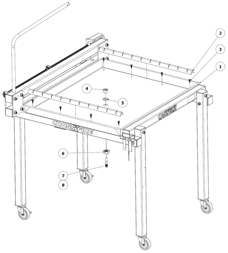 Note: Gantry assembly hidden from view.
- If standard slat holders and brackets are already installed on the CrossFire, remove these items before proceeding with water table installation.
- Place water table in position so that it is resting on top of the two ‘CrossFire’ tubes. Visually center the water table between the ‘Langmuir Systems’ square tube and the ‘Lower Rail’ square tube. Also center the water table so that it overhangs the ‘CrossFire’ tubes equally on both sides. Clamp the water table in position with standard C-clamps.
- Using a screw gun or nut driver, fasten the water table to the ‘CrossFire’ tubes with the included eight Self-Drilling Sealing #10 Screws (#3). These fasteners are self-drilling and will penetrate the ‘CrossFire’ tubes before threading into place. Clear any cutting chips between the rubber seal and water table and water table and the ‘CrossFire’ Tubes. Note: do not overtighten or risk stripping screws and/or tubes. Simply seat the screws enough to compress the Nitrile washer gently.
- Install the Brass Tank Fitting (#4) into the water table hole with the Nitrile O-ring (#5) positioned as a washer on the underside of the tank fitting flange.
- From the underside of the water table, fasten the 1”-8 Hex Nut (#6) to the Brass Tank Fitting. Tighten nut.
- Install the Drain Plug (#7) into the internal threads of the Brass Tank Fitting and tighten.
- Place the two Slat Holders (#2) inside the water Table so that they are resting in position above each ‘CrossFire’ tube. The 8 sealing fasteners should be covered up completely by the slat holders.
- Fill water table with a mixture of water and a plasma compatible rust inhibiting solution to the desired level. We recommend filling the water level to ¾” below the top slat surface to prevent excessive splashing during cutting.
- Place 10 slats into slat holders. Before cutting, be sure to attach plasma cutter ground clamp to the Drain Plug under the water table.
Laptop Stand Assembly
If you ordered a Langmuir Systems Laptop Stand, please follow these instructions for assembly.
Materials
Parts
- (1) Tray
- (1) Vertical Support
- (1) Mounting Bracket
Hardware
- (4) Laptop Stand HW Flathead Screw, 10-32 x ½"
- (4) Laptop Stand HW Washer, #10
- (4) Laptop Stand HW Locknut, 10-32
- (2) Laptop Stand HW Socket Head Cap Screw, ¼-20 x ½"
- (2) Laptop Stand HW Washer, ¼"
- (2) Laptop Stand HW Serrated Flange Nut, ¼-20
Tools
- Phillips Head Screwdriver
- 3/8 Wrench
- 7/16" Wrench
- 3/16" Hex Key
- 9/16" Wrench

Instructions
- Secure the Tray to the Vertical Support using the Laptop Stand Hardware depicted.
- Secure the Vertical Support to the Mounting Bracket using the hardware depicted. The screws can be left slightly loose if swivel capability is desired.
- Attach this Laptop Stand Assembly to the front left corner of the machine using the Stanchion Plate bolts.
Plasma Cutter Wiring
CNC Compatible Razorweld Plasma Cutters
If you purchased a CNC - CrossFire Compatible Razorweld Plasma cutter (Razorcut 45 CNC or Vipercut 30 CNC) from Langmuir Systems, your plasma cutter is plug and play with your CrossFire CNC system. Use the provided Torch Firing Cable to plug directly into the CNC Port on your Razorweld Cutter.
The CrossFire was designed to be compatible with plasma cutters that are equipped with a hand torch or machine torch. A hand torch enables the operator to start and stop the cutting action by squeezing and releasing the torch trigger. This section contains the instructions for a hand torch.
When installed on the CrossFire, the electronics system must have control over when the torch turns on and off. Providing this control requires splicing into the wires that connect to the trigger so that the CrossFire’s onboard relay can fire the torch when commanded to do so by the CPU.
The purpose of this section to provide the general procedure required to make the wire splices inside of your plasma cutter to facilitate mechanized cutting on the CrossFire. The procedure was designed to be as easy and minimally invasive as possible while preserving your plasma cutter’s ability to be used for hand cutting when not used on the CrossFire. Since there are dozens of plasma cutters on the market, the procedure is intentionally general so that it may be applied to any compatible plasma cutter you select.
Warranty and Safety Considerations
Splicing into the torch trigger wires may or may not violate your plasma cutter’s warranty. It is your responsibility to check with your plasma cutter manufacturer regarding the terms of the warranty and whether or not executing the splicing procedure violates those terms. Langmuir Systems will not be held responsible for warranty violations.
Completing the procedure requires opening up the cabinet of your plasma cutter power supply which will expose you to high voltage and high amperage electrical components. It is your responsibility to make sure that all work is done safely and with the power disconnected. If you have any doubts regarding your ability to safely perform this work, we strongly urge you to solicit the services of a professional electrician. Langmuir Systems will not be held responsible for any injury or death resulting from the incorrect or unsafe execution of this procedure.
After the wire splices are made, it is critical to never leave the torch firing cable connected to the CrossFire electronic enclosure when the torch is not installed in the torch mount and ready to cut. If the torch is required for hand cutting duty, it is imperative to first disconnect the torch firing cable before removing the torch. Failure to do so creates the opportunity for the CrossFire electronic system to turn the torch on when the torch is physically in an unsafe location; such as in the presence of volatile or explosive substances. Failure to disconnect the torch firing cable from the electronic enclosure when the torch is not installed can cause serious injury or death. Langmuir Systems will not be held responsible for any injury or death resulting from the lack of adherence to this critical safety requirement.
A test light or a multi-meter with continuity measuring capability is required to complete this procedure. Your plasma cutter may be different than the one shown so you may find that the procedure for your specific plasma cutter may need to differ somewhat.
Materials
Parts and Hardware
- Plasma Cutter
- Torch Wiring Torch Wiring
Tools
- Multimeter (or equivalent capable of measuring continuity)
- Hand tools (for opening Plasma Cabinet)
- Tape or other method of depressing torch trigger
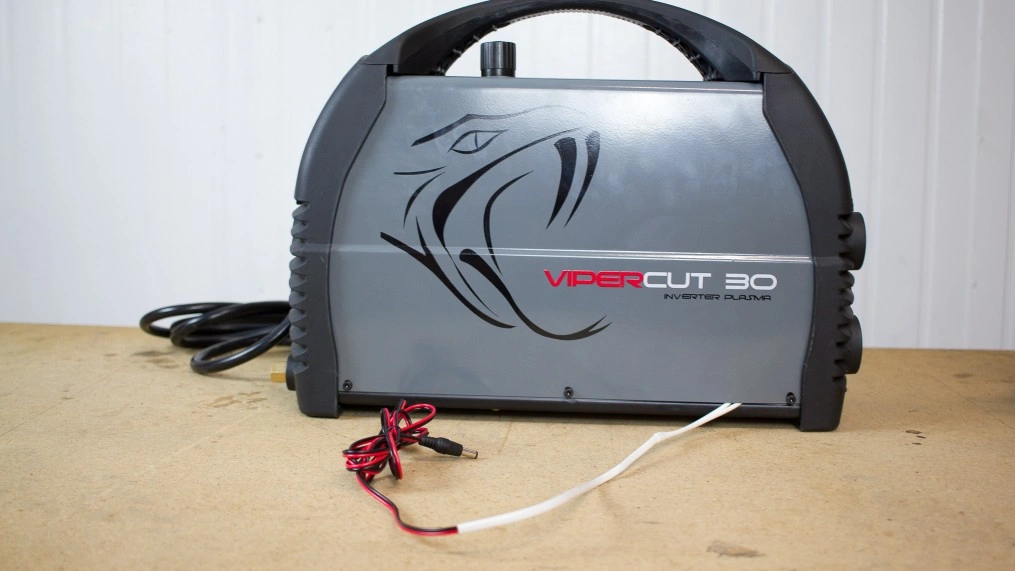
0: Gather Materials and Discharge
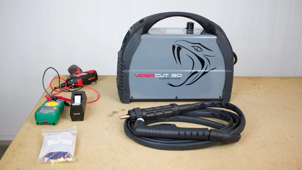
Find Torch wiring hardware (Bag #14) and your plasma cutter. We'll be using the Razorweld Vipercut 30 in this example.
Unplug your plasma cutter and wait for at least 10 minutes before proceeding in order to provide sufficient time for the internal capacitors to discharge.
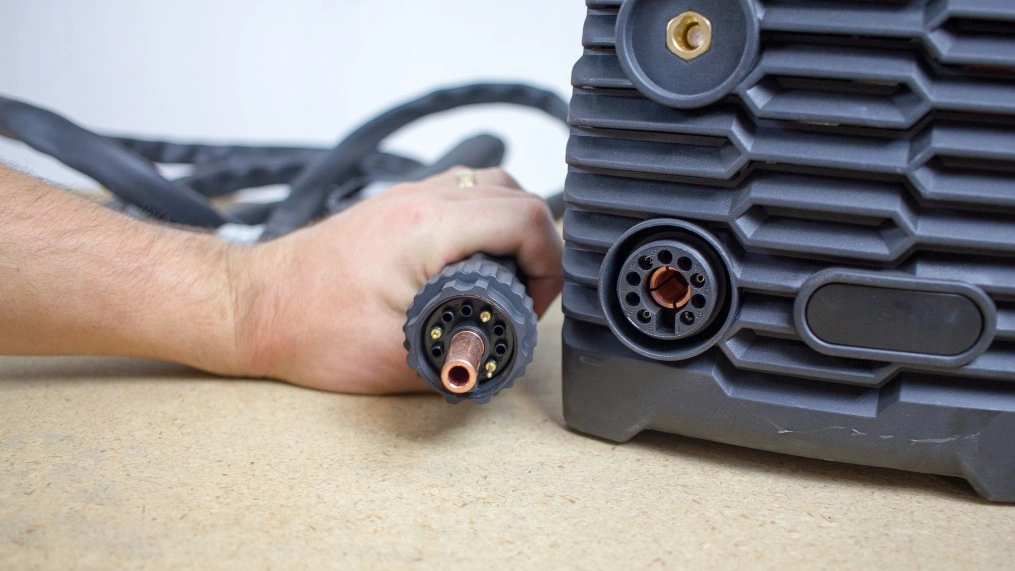
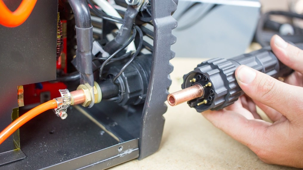
Disconnect the torch hose from the plasma cutter power supply.
1: Check for Continuity - Trigger Not Depressed
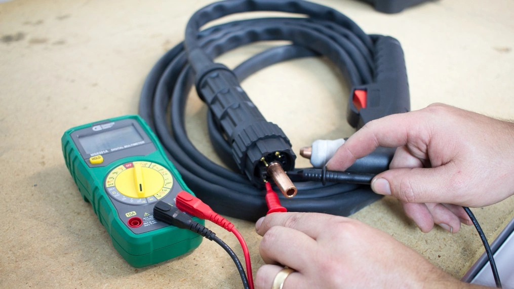
With the trigger not depressed, use your multimeter to check if there is continuity between any sets of pins. If there is continuity between a set of pins, make note of them.
2: Check for Continuity - Trigger Depressed
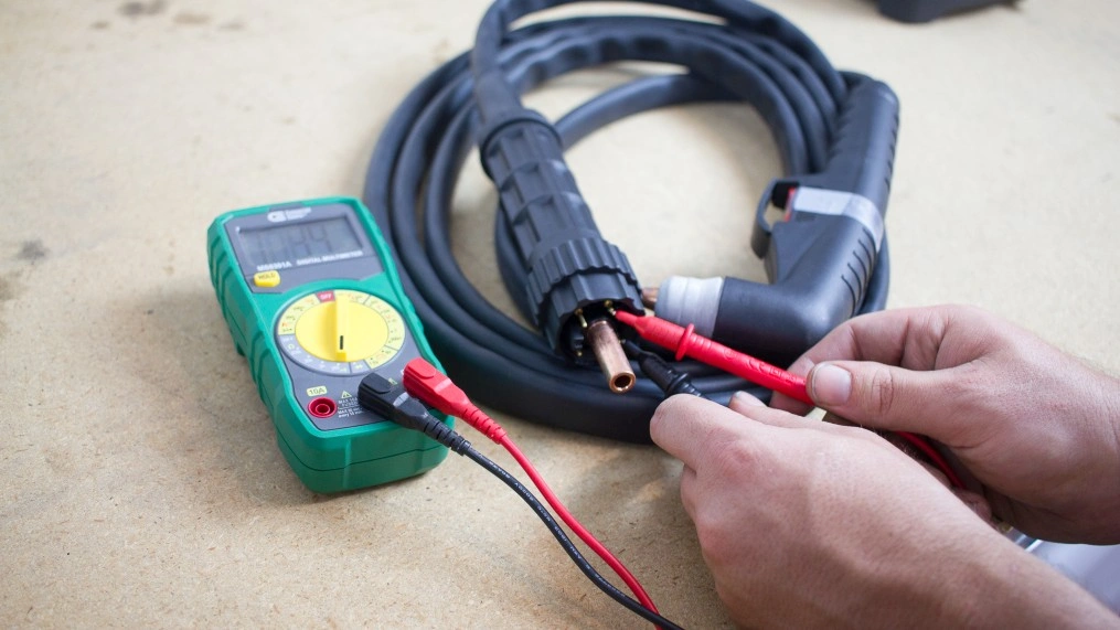
Use a piece of tape to temporarily depress the torch trigger.
Again check for continuity between sets of pins with your multimeter.
The set of pins that did not have continuity when the trigger was not depressed, but do now, are the trigger wire pins. Make note of their location in the connector.
3: Pin Comparison
Make note of the location of the trigger wire pin receivers in the female connector on the plasma cutter.
4: Open Cutter Cabinet
Remove the cover of your plasma cutter cabinet. Some plasma cutters will require tools to accomplish this. The objective is to gain access to the wires that connect to the torch hose connector mounted to the exterior of your plasma cutter.
Once open, identify the wires inside of the plasma cutter cabinet that correspond to the trigger wire pin receivers in the female connector.
5: Attach T-tap Connectors
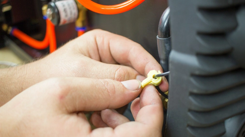
Attach the T-tap connectors to the trigger wires. You may need to use a set of pliers to clamp them onto the wires to ensure that the clasps fully lock.
Langmuir Systems provides 3 different sizes of T-taps for different gauge wires. Please use the appropriately sized tap for your wire: Not too wide of a slot so it doesn't cut the wire insulation and not too tight where you can't snap it on.
Once snapped into place, work the connector back and forth a few times (half turns) to ensure the insulation is cut and the metal is exposed to the connector.
6: Connect Torch Firing Cable
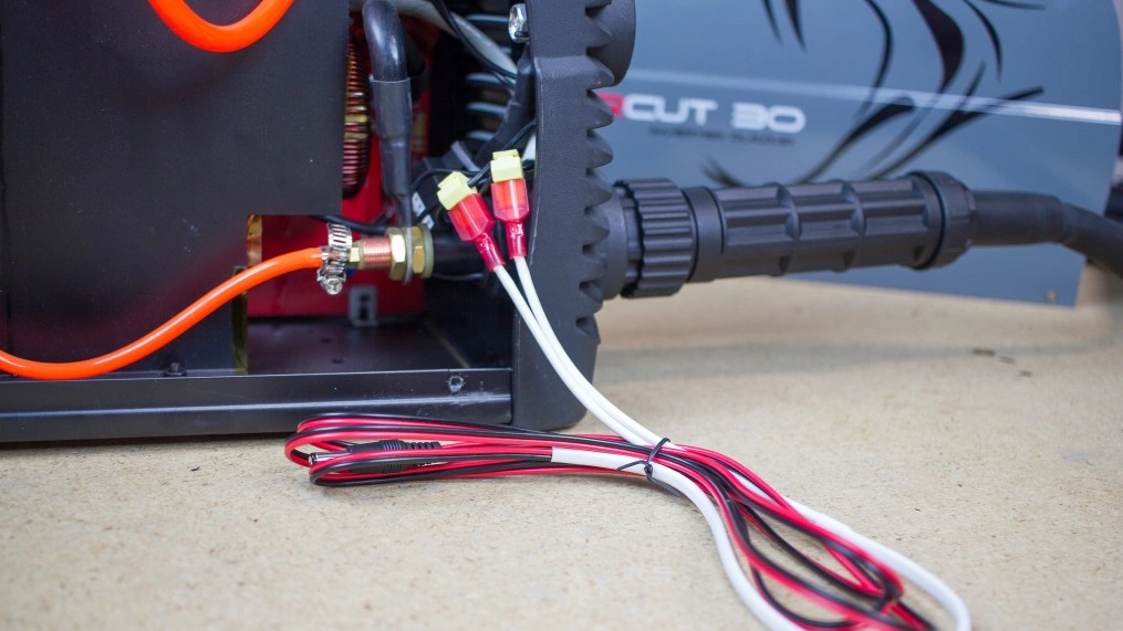
Locate the torch firing cable that was provided with your machine and connect the blade connectors to the T-Tap connectors.
It does not matter which blade connector gets plugged into which T-tap connector. The polarity and wire coloring is not important.
7: Torch Wiring Test
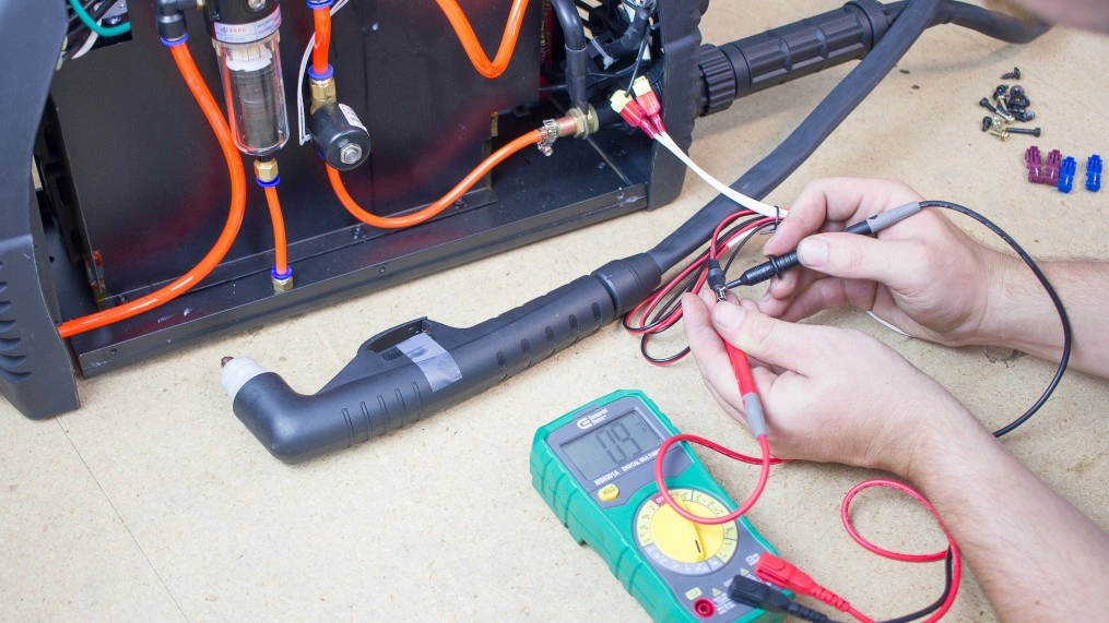
Plug the torch hose back into the plasma cutter.
With the torch trigger depressed, check the continuity between the two bare ends of the torch fire cable. If you spliced into the correct wires, there should be continuity. If not, go back and verify that the correct wires were identified in Step 3.
Release the trigger. Verify that there is no longer continuity between the two bare ends of the torch fire cable.
8: Close Plasma Cutter
Reinstall the cover on the plasma cutter cabinet with the torch fire cable exiting the cabinet in a convenient location. Make sure that there are no sharp edges that could damage the torch fire wire insulation. Add additional abrasion protection as needed.
9: Plug in Plasma Cutter
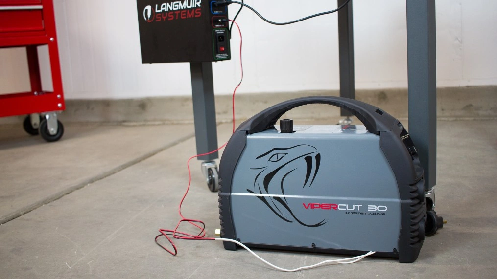
Plug the male end of the torch fire cable into the 'Torch On/Off' jack in the electronics enclosure.
As instructed in our cutting tutorials, plug in the plasma cutter with torch installed only when the torch is installed into the Torch Mount for firing safety.
What's Next
1
Install Design Software
View the Software Workflow and follow along our Fusion 360 CAD and CAM guide to start designing parts!
2
Install FireControl
Use the FireControl Guide to Download and install the software used to control your CrossFire.
3
Run the Break-in Program
Download the CrossFire Gen2 Break-in program from our Downloads page and run it using FireControl.
4
Make your First Cuts
Start cutting out parts with your CrossFire!
Legal
Warranty
All Langmuir Systems products are covered by a 12 month limited warranty on hardware and 6 month limited warranty on electronics. The terms of the warranty are listed below:
- Warranty benefits only apply to the original purchaser and expire if goods are resold. You must provide proof of purchase and your machine's unique serial number (if applicable) via email before a warranty claim may be filed.
- The buyer has 30 days after delivery to report and request to receive any missing items. Langmuir Systems will ship the missing items to the buyer within 10 business days. Langmuir Systems has the right to refuse replacement of items to any buyer that it suspects may not be truthful. The buyer is responsible for the replacement of any missing items after the 30 day period expires.
- Langmuir Systems guarantees the goods received to be defect free for a period of 12 months for
mechanical hardware and 6 months for electronics. Items that meet the following conditions will be
replaced free of charge:
- Items that are received in defective and unusable condition.
- Items that become defective and unusable after use as a result of a manufacturing, design, or material defect.
- The warranty does not cover the following types of defects:
- Defects that do not negatively affect the items functionality. Examples may include scratches, dings, dents, and surface abrasions.
- Defects that are caused by improper assembly.
- Defects that are caused by improper use.
- Defects that are caused by inadequate or incorrect routine maintenance.
- Defects that are caused by improper storage of the item or exposure of the item to the elements.
- Defects that are caused by normal wear and tear.
- If a damaged or defective item is covered by the warranty, Langmuir Systems reserves the right to request that the defective item be shipped back before supplying a replacement. Langmuir Systems will supply a shipping label to cover the expense of the return shipment. The Buyer is responsible for handling and packaging. Langmuir Systems will ship either a refurbished or brand new replacement item within 5 business days of receiving the defective item.
Return and Refund Policy
All products sold directly by Langmuir Systems are eligible for return and refund. The terms of the return and refund policy are listed below:
- Only the original buyer of the item is eligible to return the item for a refund. Proof of purchase is required in order to be eligible for a refund.
- A return must be requested within 30 calendar days following the delivery of the item. Return requests after the eligibility period will be denied.
- The buyer is responsible for all shipping and handling costs associated with shipping the item back.
- Items that are eligible for return must meet all of the following requirements:
- The item must be in unused condition.
- The item must be free of defects.
- The item must be received in the original packaging.
- Langmuir Systems will inspect the item within 5 business days of receiving it. The buyer will be informed if it passes inspection and thus is eligible for a refund.
- If Langmuir Systems concludes that the item meets the refund eligibility requirements, a refund for the original transaction amount minus a 20% restocking fee will be issued to the Buyer within 5 business days following the completion of the inspection.
- 'In person' returns require permission from Langmuir Systems in advance.
- All purchases are subject to a non-refundable 2.4% merchant transaction fee.