Autodesk has renamed the CAM Workspace to the MANUFACTURE Workspace. All of the same functions are still available within this workspace.
CAD/CAM with Fusion360
Introduction
These tutorials aim to get you cutting with your CrossFire by guiding you through all the steps from creating a digital design to firing your torch. They can be used as baseline knowledge for a novice or as short refreshers for those with some digital fabrication experience.
There are two pieces of software that are needed in order to cut parts on your CrossFire™ machine. Please follow continue through this guide for in-depth video guides on how to use these programs.
CAD: Design your Part
Autodesk Fusion 360 is a powerful design CAD and CAM software that is free to use for hobbyists and startups with less than $100k revenue per year. This software can be downloaded from our website or directly from Autodesk. You can design your own custom 2D & 3D parts right in Fusion, or you can simply import your own part files from your favorite CAD program. The software is easy-to-use for beginners new to drafting, and Autodesk has published an ever-growing library of tutorial videos to follow along and learn.
1: Installing Fusion 360
Download and install Fusion 360 and activate as a hobbyist or small business if you qualify.
2: Starting a Sketch
Start your first sketch and learn to move around in Autodesk Fusion 360.
3: Basic Dimensions
Beginning a Fusion 360 Project showing basic dimensioning and sketch functions.
4: Constraints
Using the Fusion 360 sketch palette, constraints, and fillets.
5: Importing Files
Import files from other programs into Fusion 360 for CAM. DXF, Mesh, and SVG vector files are easily imported in Fusion 360.
6: Move, Copy, and Scale
We cover moving portions of your sketch, copying and pasting sketch selections, and scaling.
7: Sketch Text
We cover the text function in Fusion 360 and how you need to be careful choosing your fonts for CNC Plasma cutting.
8: Mirroring and Patterning
We cover the sketch mirroring and patterning functions in Fusion 360 using example project files from our website.
9: Trim, Extend, Offset
Trimming, Extending, and Offsetting your sketches in Fusion 360.
10: Save, Export, and Offline Mode
Saving, exporting and what you can and can't do with Fusion 360 when you're not connected to the internet.
CAM: Program your Part
The next step in the process is to create the toolpaths from the part file that will be followed by the CrossFire™ machine when cutting. Once your part is designed, you will use Autodesk Fusion 360's plasma CAM feature to program toolpaths based on the part geometry that you want to cut. Here you will specify cutting parameters such as cut speed, pierce delay, and lead-in geometry and Fusion will export these toolpaths as a G-code file that can be read by the machines controller software.
UPDATE 1/9/19
1: The Fusion 360 MANUFACTURE Workspace
We cover CAM and Toolpaths, the MANUFACTURE workspace in Fusion and what functions you'll be using to start generating toolpaths for your CrossFire.
2: Creating a Plasma Cutting Tool
We cover creating a Plasma Cutting Tool with an accurate Kerf width and nozzle diameter.
3: Creating a Setup
Create a setup for the profile cutting operation that describes your stock, cutting tool, and origin.
4: Profile Toolpath Generation
We cover all of the toolpath configurations you need to generate a profile cut toolpath in Fusion 360 and then simulate that toolpath.
WARNING
When generating toolpaths for the CrossFire PRO with THC, use NO lead out to avoid losing arc voltage at the end of a cut.
POST: Exporting your Part
Posting Programs from Fusion 360 translates your designed and programmed parts into files specific for the CrossFire CNC. Note: CrossFire and CrossFire PRO machines now ship with Gen2 electronics and require the use of FireControl software to operate.Legacy CrossFire 2x2 machines use Mach3 for which the instructions are found in the next section.
FireControl with Z-Axis
The following guide provides instructions for generating cutting programs in Autodesk Fusion 360 for running in FireControl software. This guide assumes that you are already familiar with performing CAM operations in Fusion 360 for creating cutting programs; if not, we suggest first watching our Fusion 360 CAM video series (videos 1-4) in this guide before proceeding.
- If your CrossFire machine is equipped with a powered Z-axis, you will want to
go back and make sure that the box for ‘Keep Nozzle Down’ is left unchecked
in the Linking menu of your CAM settings.
![]()
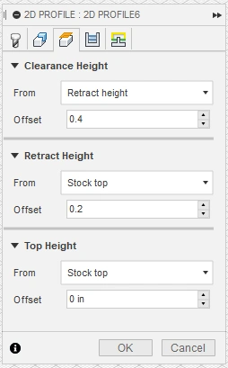
- Actual Pierce and Cut Height Values will be set in the Post Processing step below. However, Clearance Height, Retract Height, and Top Height
need to be left to the Fusion360 defaults to properly set heights in your G-code program.
Be sure to have these values set to the below.
![]()
- By this point, you should already have a valid toolpath created in Fusion 360
for your part similar to what is shown below.
![]()
- Next, we are going to generate a G-Code file for this tool path using the Post
Processor in Fusion 360. A G-Code file is a set of text instructions that are
fed to the CrossFire CNC electronics box through FireControl software for
telling the machine where, how, and when to move in order to cut out the part.
To do this, click on the Post Processor icon (below) in the Additive menu bar.
![]()
-
If this is your first time posting a program for FireControl in Fusion 360,
you will need to open an internet browser and download the ‘Langmuir Systems Fusion 360 for FireControl Post Processor’
file from the Downloads page on our website. Once the file downloads to your computer,
take note of the location of this file in your computer's Downloads folder or after moving this file to another permanent location.
For MacOS users, please follow the instructions provided by Autodesk for installing Personal Posts for Fusion 360.![]()
- Go back to Fusion 360 and click the square icon with 3 dots next
to the text field for Post in the Machine and post subheading.
![]()
- In the Post Library submenu, click Local on the left-hand side and make sure that it is highlighted.
![]()
- With Local highlighted, select the Import option near the top of the window.
![]()
- In the Import submenu, select your Downloads folder (or other permanent location) on the left-hand side of the window,
click to highlight the post processor file, and click Open in the bottom right-hand corner of the window.
![]()
- You will now see the Langmuir Systems FireControl post processor every time you highlight Local
in the Post Library submenu. Click Select in the bottom right-hand corner of the window.
![]()
- Next we need to designate an output folder for the g-code programs that we
are going to create. We recommend first creating a folder on your Desktop
that you can store these generated programs in. To select an output folder,
click the square icon with 3 dots next to the text field for Output Folder
and locate your desired output folder for your programs. Here we’ve created a
folder on my Desktop titled ‘Fusion 360 CrossFire Programs’ for easy access.
![]()
- Next, in the Program subheading we can type in a Program Name or number and
a Program comment (as needed). Then, select the appropriate units for your
cutting program and make sure that the boxes next to ‘Post to Fusion Team’
and ‘Open NC file in editor’ are unchecked. Your settings should look similar
to what is shown below.
![]()
- Next, we are going to enter our desired cutting parameters for this program.
Below is an explanation of these Properties and how they affect your cutting
program. You can disregard any other properties not mentioned in this menu as
they should be left to the default settings.
![]()
- Cut Height (in): This is the desired cutting height for your plasma torch above the surface of the plate. Consult your plasma cutter documentation for the ideal cut height for your torch and material. If you are using a CrossFire without a powered Z-axis, set this value to 0.
- IHS Springback (in): Use this value to add additional cutting height to your plasma torch when cutting on thin gauge sheet metal to account for the force of the IHS switch. The IHS switch applies approximately 2lbs of force to your material when detecting the plate height and this springback value can compensate for the deflection. If you are using a CrossFire without a powered Z-axis, set this value to 0.
- IHS: Use this toggle to enable or disable Initial Height Sensing switch on your machine. If you are using a CrossFire without a powered z-axis, set this value to No.
- Pierce Delay (sec): The pierce delay value is the amount of time that the torch remains stationary after firing in order to fully pierce the material before moving down to the Cut Height. The pierce delay is dependent on your plasma cutter and the thickness of material being cut. Please consult your plasma cutter documentation for appropriate pierce delay settings for your cutter.
- Pierce Height (in): The pierce height is the height above the plate that is used for the initial piercing process. The pierce height should be larger than the Cut Height and is typically about twice the value of the cutting height. If you are using a CrossFire without a powered Z-axis, set this value to 0.
- Retract Height (in): The retract height is the height above the plate that the torch retracts up to after finishing each cutting loop before rapid moving to the next cutting loop. This retraction is key for avoiding tip ups and warped material when moving the torch to the next cutting location on the material. Please make sure that your selected retract height does not exceed the Z-axis travel limits of your machine. If you are using a CrossFire without a powered Z-axis, set this value to 0.
- THC: Use this toggle to enable or disable THC for your cutting program. If you are using a CrossFire without a powered z-axis, set this value to No.
Typical Properties for CrossFire without Powered Z-axis
![]()
Typical Properties for CrossFire with Z-axis and THC
![]()
- After completing your cutting properties, click the Post button (below) to create your g-code
program. Your program will be stored in the Output Folder from Step 10.
![]()
- Finally once your program is created successfully, you can now open FireControl
and upload your program for cutting.
![]()


FireControl without Z-Axis
If you are running a CrossFire with Gen2 electronics and no Z-Axis, IHS, or THC the only Post variable you need to set is the Pierce Delay value. However, be sure to set:
- IHS
- THC
settings to 'No' in Windows or unchecked in MacOS. You can also set the additional variables in blue below to 0, but these will not affect the cut.
Typical Properties for CrossFire without Powered Z-axis

Post Processing for Mach3 (Legacy CrossFire)
If using a Legacy Gen 1 CrossFire, follow the above instructions to install the Mach 3 Post Processor instead using the 'CrossFire Fusion 360 Post for Mach3' available in Langmuir Systems Downloads.
SheetCAM Post Processing has been moved to its own page.