CrossFire XR Assembly Guide
Safety
When used correctly, the Langmuir Systems Crossfire XR Plasma Table will offer you years of safe operation. However, like all other automated and industrial type machinery, there are important safety considerations and precautions that must be followed in order to avoid injury. Study these safety warnings carefully before assembling and using your machine.

ELECTRIC SHOCK
Electric shock can cause serious injury or death. This machine requires the use of high voltage electricity to operate. To avoid injury, always adhere to the following precautions:
- Never touch bare wires/buses/connections or components that are carrying electricity.
- Repair or replace all worn or damaged components. Turn off power to machine and plasma cutter when making repairs.
- Install and maintain equipment in accordance with the National Electric Code (NEC)
- If you have limited electrical knowledge/experience, hire a certified electrician to perform all electrical work.

FIRE AND EXPLOSION
Fire and explosion can be caused by the airborne sparks and slag igniting a nearby flammable material. Electrical fires can be caused if the machine is assembled or used incorrectly. To avoid injury, always adhere to the following precautions:
- Never operate the machine in the vicinity of flammable materials or where there is volatile and combustible fumes in the air.
- Do not use the machine to cut materials or parts that have previously contained fuel or flammable substance of any kind such as gas tanks.
- Always keep a fire extinguisher nearby in case of emergency.
- Never operate the machine in a poorly ventilated area.

AUTOMATIC OPERATION
The machine may operate at any time, automatically, and without warning. To avoid injury, always adhere to the following precautions:
- Acquire sufficient training before operating the machine.
- Never place any part of your body in direct contact with areas of the machine that can pinch and crush when powered on. Assume that if the machine is powered, it may move at any time.
- Keep area clear of bystanders, make sure that no one but the person operating the machine has access to the computer controls.

HAZARDOUS FUMES
Gases and fumes produced during the plasma cutting process can be hazardous to your health. To avoid injury, always adhere to the following precautions:
- Keep all fumes and gases from the area in which you breathe. Never operate the machine in an area with minimal or no ventilation. Use fans and blowers to remove fumes and gases from the work area.
- If ventilation is poor, use an air-supplied respirator system.
- The type of fumes and hazard level depends greatly on the type of metal being cut. Before cutting, consult the Material Data Safety Sheet (MSDS) for specific guidelines on the type and hazard level of the fumes produced during cutting.
- Never cut materials that has been coated with paint, oil, grease, or solvents.

ULTRAVIOLET AND INFRARED RADIATION
The plasma cutter produces high intensity ultraviolet and infrared light that can damage your eyes and skin. To avoid injury, always adhere to the following precautions:
- Never operate the machine without sufficient eye protection. Consult the user manual for your plasma cutter to determine the minimum protective shade required for the amperage of your machine. Alternatively, consult ANSI/ASC Z49.1.
- Wear gloves and suitable clothing to protect your skin at all times.
- Always alert bystanders before you begin cutting. Bystanders in the immediate vicinity must wear suitable eye and skin protection. Use welding screens whenever possible.

SPARKS AND AIRBORNE DEBRIS
Plasma cutting creates airborne sparks and debris that can cause eye injuries. To avoid injury, always adhere to the following precautions:
- Always wear suitable eye protection when operating the machine. Eye protection should follow the guidelines established in ANSI Z87.1.
- Ensure that all bystanders in the immediate vicinity are wearing suitable eye protection.

PINCH AND CRUSH POINTS
This machine can create pinch points while in motion during normal operations. To avoid injury, always adhere to the following precautions:
- Do not touch any part of the machine when it is moving under power.
- Be aware of all areas of the machine that could potentially be a pinching hazard, such as bearings, lead screws, lead nuts, and slides.
- Never make repairs to the machine when the machine is powered on.

HOT MATERIALS
The plasma cutting process uses extremely high temperatures to cut metal. As a result, the material can be very hot after cutting which can cause burns. To avoid injury, always adhere to the following precautions:
- Always assume that metal resting on the machine is hot enough to cause severe burns.
- Always allow the metal to sufficiently cool before handling. Use a bucket of water to cool down part before handling with bare hands.
- Never handle hot metal with bare hands. Use gloves or tongs to remove material from the machine.
WARNING
This product can expose you to chemicals which are known to the State of California to cause
cancer, birth defects or other reproductive harm. For more information go to www.P65Warnings.ca.gov.
Getting Started
1
Assemble Your XR
Use the following CrossFire XR Assembly Guide to put together your machine.
2
Set up your MC4000 Windows PC
View the MC4000 Initial Setup section of this guide and follow along to set up your Mini-PC.
3
Install FireControl
Use the FireControl Guide to Download and install the software used to control your XR.
4
Run the Break-in Program
Download the XR Break-in program from our Downloads page and run it using FireControl.
5
Make your First Cuts
Start cutting out parts with your XR!
CrossFire XR Assembly
The Langmuir Systems CrossFire XR ships partially assembled. Therefore, this section serves to provide all of the pertinent information and instructions needed to fully assemble your new machine.
Images in this Guide
The assembly drawings and pictures included in this guide can be expanded to
full-screen and zoomed to provide more detail on a given step.
0: Uncrating
The CrossFire XR is delivered in 2 crates to make the kit manageable to ship. An in-depth description of what is inside is provided here. Please use this as a reference for the rest of the assembly.
Uncrating Ball Screws
CrossFire XR Ball Nuts are shipped installed on the ball screws in Crate #2 and under no circumstances should
they be removed from the screws during assembly. Removing ball nuts from ball screws will require the replacement
of the ball nut at significant cost.

XR Crate #1 (Large)
- (1) FRONT FASCIA PACKING ASSEMBLY
- (2) TABLE SLAT BUNDLE
- (1) X-AXIS CABLE TRAY
- (1) TOUCHSCREEN MONITOR SUB BOX
- (1) XR GANTRY TUBE
- (1) XR X-AXIS DRAG CHAIN
- (1) XR Y-AXIS DRAG CHAIN
- (1) X/Z-AXIS ASSEMBLY SUB BOX
- (2) WATER TABLE SLAT HOLDER BUNDLE
- (1) WATER TABLE END TRAY BUNDLE
- (1) WATER TABLE EXTENSION TRAY BUNDLE
- (1) MISC STEEL BRACKETS SUB BOX
- (1) GANTRY UPRIGHT ASSEMBLIES SUB BOX
- (1) XR ELECTRONICS ENCLOSURE SUB BOX
- (1) MISC PARTS SUB BOX
- (1) CONTROLLER COMPUTER & THC SUB BOX
- (1) CROSSFIRE XR HARDWARE SUB BOX
XR Crate #2 (Long)
- (1) UPPER LONGITUDINAL CHANNEL PACKING ASSEMBLY
- (2) Y-AXIS RAIL
- (2) Y-AXIS BALL SCREW ASSEMBLY
- (1) X-AXIS BALL SCREW ASSEMBLY
1: Install Leveling Feet
The first step in CrossFire XR assembly is installing the lower lateral channels onto the front fascia and installing leveling feet.
Materials
Parts
- (2) Front Fascia Panel
- (2) Lower Lateral Channel Weldment (INSIDE FRONT FASCIA PACKING ASSEMBLY)
- (4) Leveling Foot (MISC. SUB BOX)
Hardware
- (16) BAG 8 BUTTON HEAD CAP SCREW, 3/8-16 X 5/8
- (16) BAG 10 FLANGED HEX NUT, 3/8-16
Tools
- 7/32” HEX
- 9/16” WRENCH
- 30mm or ADJUSTABLE WRENCH

Instructions
- Locate one Lower Lateral Channel Weldment and screw a Leveling Foot into the weldnuts at each end as shown. Leave approximately 1” of exposed thread below the weld nut. Seat the jam nuts but do not tighten them. The Leveling Feet will be fine adjusted in a later step.
- Attach the Lower Lateral Channel Weldment to the Front Fascia Panel using the fasteners shown. Tighten the screws.
- Repeat Steps A1-2 for the second assembly.
2: Frame Assembly
Next, attach the longitudinal channels to the Front Fascias previously assembled.
WARNING
Due to the size and weight of these components, a helper is recommended to perform this assembly step.
Materials
Parts
- (2) Front Fascia Sub-Assembly (FROM PREVIOUS STEP)
- (2) Lower Longitudinal Channel (INSIDE UPPER LONGITUDINAL PACKING ASSEMBLY)
- (2) Upper Longitudinal Channel
Hardware
- (24) BAG 8 BUTTON HEAD CAP SCREW, 3/8-16 X 5/8
- (24) BAG 10 FLANGED HEX NUT, 3/8-16
Tools
- 7/32” HEX
- 9/16” WRENCH

Instructions
-
Attach the two Upper Longitudinal Channels to the Front Fascia Sub-Assemblies using (16) BAG 8 screws and (16) BAG 10 nuts. Only hand tighten the fasteners at this time.
Important NoteThe orientation of the Upper Longitudinal Channels is critical. The 4 large holes should be located at the top of each channel as shown.
- With the ‘Langmuir Systems’ logo facing up, attach the two Lower Longitudinal Channels to the legs of the Front Fascia using (8) BAG 8 screws and (8) BAG 10 nuts. Only hand tighten the fasteners at this time.

Instructions
- Adjust the Upper Longitudinal Channel up or down until the top surface is flush with the top surface of the Front Fascia and then tighten the four screws to lock it in position. Make sure that large hole at the top of the Front Fascia is in alignment with the mating hole in the Upper Longitudinal Channel.
- Repeat Step B1 for the remaining 3 corners.
- Tighten the screws that secure the Lower Longitudinal Channels.
Materials
Parts
- None
Hardware
- None
Tools
- Tape Measure
- BUBBLE LEVEL
- 30mm or ADJUSTABLE WRENCH

Instructions
- Make adjustments to the Leveling Feet until all four locations marked with a red line are shown to be level. Once satisfied, tighten the leveling feet jam nuts. Note: The flatter and more level this surface is, the higher the water level can be in the water table.

Instructions
Important Note
Failure to adequately square the machine frame can lead to issues with machine binding and cutting
accuracy. Be certain to keep the frame square while assembly until the frame position is locked
in during the Water Table assembly.
- The goal of this step is to square the frame of the machine. Using the tape measure, measure the diagonal distances shown by the red and green arrows. Push and/or pull the Front Fascia in the direction indicated by the blue line in order to make the diagonal distances equal to each other within 1/8”.
Materials
Parts
- (1) Frame Assembly (FROM PREVIOUS STEP)
- (1) Touchscreen Stiffener Bracket (MISC. STEEL BRACKETS SUB BOX)
Hardware
- (2) BAG 8 BUTTON HEAD CAP SCREW, 3/8-16 X 5/8
- (2) BAG 10 FLANGED HEX NUT, 3/8-16
Tools
- 7/32” HEX
- 9/16” WRENCH

Instructions
- Decide which end of the machine you want to be the front. Note that when facing the front of the machine, the Touchscreen and PC will be mounted on the lefthand corner.
- Locate the Touchscreen Stiffener Bracket and secure it to the Upper Longitudinal Channel and front fascia using the fasteners shown.
- Tighten the screws.
3: Gantry Assembly
Assemble the gantry by attaching the upright assemblies to the gantry tube and X/Z Axis assembly.
WARNING
Due to the size and weight of these components, a helper is recommended to perform this assembly step.
Gantry Tube Break-In
The bearings of the X/Z-axis carriage will wear a path into the Gantry Tube powder coating as your XR Machine
breaks in. This is expected and will not affect performance.
Materials
Parts
- (1) LH Gantry Upright Assembly
- (1) RH Gantry Upright Assembly
- (1) Gantry Tube
- (1) X/Z-Axis Assembly
- Gantry All-Thread Rod (INSIDE UPPER LONGITUDINAL PACKING ASSEMBLY)
Hardware
- (2) BAG 11 FLANGE NUT, M10 X 1.5
Tools
- 15mm WRENCH

Instructions
- Locate the Gantry Tube and set it on two supports with a gap in between them. A set of sawhorses works well for this.
- Locate the X/Z-Axis Assembly and slide it onto the Gantry Tube until it is positioned between the two supports placed in Step A1. Note that the X-Axis preload bearings are fully retracted and it is normal for excessive lash to be present. The bearing preloads will be set in a later step.
- Insert the Gantry All-Thread Rod into the Gantry Tube, letting it overhang the ends approximately evenly.
-
Secure the LH and RH Gantry Uprights to the gantry tube using the gantry all thread rod and BAG 11 flange nuts shown.
Torque the nuts to roughly 30 ft-lb. Important Notes:
- This step is significantly easier to accomplish with two people, each handling one Upright Assembly.
- Make sure that the LH Upright is installed on the Lefthand side; and vice versa for the RH Upright.
- The bottom and back edges of the Gantry Tube should be resting firmly against the locating edges machined into the face of the uprights when tightening the flange nuts. These edges are responsible for ensuring the Gantry Tube remains parallel to the slat bed, and perpendicular to the Y-Axis of the machine. See below note for additional clarification.
Gantry Locating
The bottom and back edges of the Gantry Tube should be resting firmly against the locating edges
machined into the face of the Uprights when tightening the flange nuts as shown below. These edges
are responsible for ensuring the Gantry Tube remains parallel to the slat bed, and perpendicular to
the Y-Axis of the machine.
![]()

4: Install Limit Switches
Finalize assembly of the Gantry by installing Limit Switches and measuring the rail-to-rail dimension.
Limit Switch Cable Length
Locate the Limit Switch Cable from the Miscellaneous Sub-Box. The switch with the shortest cable
length is for the Y1 axis, the middle length is for Y2, and the longest length is for the X-Axis as shown below.
![]()

Materials
Parts
- (1) Limit Switch Cable
Hardware
- (6) BAG 22 SOCKET HEAD CAP SCREW, M2.5 X 8
Tools
- 2.0mm HEX

Instructions
- The Limit Switch Wiring Loom has the limit switches pre-installed. Lay the cable out and consult the above diagram shown to identify which limit switches are X, Y1, and Y2. It is important to properly identify the switches so that they can be installed at the proper locations.
- Use theBAG 22 Socket Head Cap Screws to secure each limit switch as shown. Note: The use of 8mm screws is intended to simplify the replacement of limit switches in the event of any issues.
- The connections to the limit switches are fragile. Take considerable care to ensure that connections are not pulled on when fastening into position. We recommend wrapping the excess cable length around the gantry tube until the cable is fastened into position at a later step.
!STOP! Y-Axis Rail Alignment
CRITICAL: You must watch and understand the following video on the process of attaching
the Y-Axis Rail to the machine accurately before proceeding with assembly. If you have printed out these instructions, do not
continue on with assembly before watching and understanding the following video.
Materials
Parts
- None
Hardware
- None
Tools
- TAPE MEASURE
- PEN & PAPER

Instructions
- Using a Tape Measure, measure and record the distance between the inside edge of two upper v-wheels on opposite sides of the gantry. This measurement will be needed in a later step to set the rail-to-rail distance of the Y-Axis rails. As such, this measurement needs to be taken with great care. This dimension will be referred to as DIM ‘A’.
5: Attach Y-Axis Rails
Next, we'll be attaching the Y-Axis rails to the machine frame.
Materials
Parts
- (2) Y-Axis Rail
- (8) Y-Axis Rail Stabilizer (MISC. SUB BOX)
Hardware
- (8) BAG 21 SOCKET HEAD CAP SCREW, ¼-20 X ½
- (8) BAG 18 M20 THIN HEX NUT
Tools
- 3/16” HEX
- ADJUSTABLE WRENCH to use for leverage with HEX

Instructions
- Attach each of the four Y-Axis Rail Stabilizers to the Y Axis Rail using the BAG 21 Socket Head Cap Screws shown. Be sure to orient the fish-mouth of the stabilizer so that the contour matches the tube surface. Note: these cap screws need to be fully tightened; if you are using the long end of an allen L-key to tighten these cap screws, we recommend using a crescent wrench on the short end of the allen key in order to apply enough torque to the bolt.
- Screw the BAG 18 M20 Thin Hex Nuts onto the Stabilizers until they contact the outer surface of the Y-Axis Rail. Do not tighten them.
- Repeat Steps A1 and A2 for the second Y-Axis Rail.
Materials
Parts
- (1) Machine Frame (PREVIOUSLY ASSEMBLED)
- (2) Y-Axis Rail Sub-Assembly
Hardware
- (8) BAG 18 M20 THIN HEX NUT
Tools
- None

Instructions
-
Install one Y-Axis Rail Assembly, making sure that each of the 4 Y-Axis Rail Stabilizers
is properly inserted into the large holes in the side of the frame.
Important NoteThis step is best completed with a second set of hands. The Y-Axis rail needs to be parallel to the Longitudinal Channel to ensure that it inserts into the 4 mounting holes. If you find that the rail stabilizers are not inserting into the holes, consider breaking loose the 4 cap screws installed in A1 and then insert the tube. Be certain to re-tighten these cap screws once the tube is inserted properly.
- Screw the four BAG 18 M20 Thin Hex Nuts onto the Y-Axis Rail Stabilizers. Each nut only needs to be screwed on 2-3 turns at this step. These will be adjusted and tightened at a later step. The rail should be completely loose at this point and able to move around with slack.
- Repeat Steps B1 and B2 for the second Y-Axis Rail Assembly.
6: Install Gantry
Next, we'll be adjusting the Y-Axis Rails to fit the previously assembled gantry and then sliding on and adjusting the gantry.
Materials
Parts
- (1) Machine Frame with attached Y-Axis Rails (PREVIOUSLY ASSEMBLED)
Hardware
- None
Tools
- TAPE MEASURE
- 30mm or ADJUSTABLE WRENCH

Instructions
Rail Alignment
The goal of the following rail alignment steps is twofold:
- to make the Y-Axis rails parallel to each other.
- to make the distance between the rails match the wheel-to-wheel distance of the gantry V-Rollers (Dimension 'A').
- Working on the Lefthand rail first (when standing at the front of the machine this is the one on your left side), adjust the inner and outer M20 jam nuts until the distance between the inner rail surface and the nearest side of the front fascias is 1.25” at each end of the rail as shown in the diagram. The inner and outer jam nuts should be hand tight at this point so that the rail is rigid when taking your measurements. The measurement at the front should match the measurement at the back within 1/16”.
- Tigthen the nuts securing the rail making sure not to move the position of the rail when fastening. To do this, carefully place a wrench on the outer jam nut without rotating the nut. While keeping this wrench in a fixed position, use a second wrench to tighten the inner jam nut. Repeat this step for the rear stabilizer (circled in red).
- Next, we are going to tighten the remaining two Y-Axis Rail Stabilizers on the Lefthand rail. Start by hand seating the inner and outer jam nuts first against the frame surface and then place a wrench on the outer jam nut without rotating the nut. Tighten the inner jam nut to secure as performed in Step A2 above.
Materials
Parts
- (1) Machine Frame with attached Y-Axis Rails (PREVIOUSLY ASSEMBLED)
Hardware
- None
Tools
- TAPE MEASURE

Instructions
- In order to align the Righthand Rail, recall DIM ‘A’ that was recorded in our previous step. Take this dimension and add 1.75” to it and record this new number. This number will be the center-to-center rail spacing dimension that we will use to set our Righthand Rail in position.
- Working on the righthand rail, adjust the inner and outer M20 Jam Nuts at the front and rear (circled in red) until the center-to-center distance of the two rails matches the value that was calculated above. The easiest way to measure this distance is to use a tape measure and measure from the inner edge of the Lefthand rail to the outer edge of the Righthand rail as shown in the diagram. The inner and outer Jam Nuts should be hand tight at this point so that the rail is rigid when taking your measurements. In order to prevent binding and accuracy error, the rails must be parallel within 1/32”.
- Tigthen the nuts securing the rail, making sure not to move the position of the rail when fastening. To do this, carefully place a wrench on the outer jam nut without rotating the nut. While keeping this wrench in a fixed position, use a second wrench to tighten the inner jam nut. Repeat this step for the rear stabilizer (circled in red).
- Tighten the remaining two Y-Axis Rail Stabilizers on the Righthand Rail. Start by hand tightening the inner and outer jam nuts first and then place a wrench on the outer jam nut without rotating the nut. Tighten the inner jam nut to secure as performed in Step 2 above.
WARNING
Due to the size and weight of these components, a helper is recommended to perform this assembly step.
Materials
Parts
- (1) Machine Frame (PREVIOUSLY ASSEMBLED)
- (1) Gantry Assembly (PREVIOUSLY ASSEMBLED)
Hardware
- None
Tools
- None

Instructions
- Working at the back of the machine, carefully slide the Gantry onto the Y-Axis Rails such that the Upper V-Rollers are able to roll on the top surface of each rail. There should be an air gap between the Lower V-Roller and the bottom side of the rail. This is normal and the Lower V-Roller preload will be set in a later step.
Materials
Parts
- (1) Machine Assembly with attached Gantry (PREVIOUSLY ASSEMBLED)
Hardware
- None
Tools
- 5/16” WRENCH
- 9/16” WRENCH

Instructions
- The goal of this step is to adjust the lower V-Rollers on both sides so that no lash exists between the gantry and its rolling connection to the Y-Axis rails.
- Check to make sure that all 4 upper V-Rollers are in contact with the Y-Axis Rails. If rocking of the gantry on the rails can be observed, break loose and then re-tighten one of the nuts that is used to secure the gantry tube to the gantry uprights. The weight of the gantry will drive all four upper V-Rollers into simultaneous contact with the Y-Axis rails.
- With one hand, lightly snug the jam nut to remove play between the axle and the upright. With the other hand, turn the eccentric axle clockwise using a 5/16” wrench on the flats (do not use a crescent wrench here) until the V-Roller just contacts the underside of the Y-Axis Rail. Next, tighten the jam nut while holding the eccentric bolt at the same position with a wrench.
- Repeat Step D3 for the lower V-Roller on the other side of the gantry.
-
Glide the gantry along the Y-Axis Rails and check to make sure the following conditions are met:
- The gantry rolls freely. A small amount of resistance is acceptable but generally it should not be hard to push the gantry from one end to the other. If there is excessive rolling resistance, decrease the V-Roller preload and check again. Note: excessive preload of the eccentric bolt can cause binding issues if the gantry is too hard to move.
- At all points of travel, there is no perceptible lash between the gantry and the rails. If lash can be felt, increase the V-Roller preload and check again.
7: Install Gantry Gussets
Materials
Parts
- (1) Gantry Tube Gusset (INSIDE FRONT FASCIA PACK)
- (1) Gantry Tube Gusset - Mirrored (INSIDE FRONT FASCIA PACK)
Hardware
- (4) BAG 6 BUTTON HEAD CAP SCREW, 10-24 X ½
- (4) BAG 36 SELF DRILLING SHEET METAL SCREW, 10 X 3/4
Tools
- ⅛” HEX
- IIMPACT DRILL GUN w/short bit
- 5/16” SOCKET

Instructions
-
Secure one Gantry Tube Gusset to the LH upright using the BAG 6 Button Head Cap Screw.
Make sure that the gusset is oriented as shown.
Important NoteBefore shooting the screws, make sure that the flange that mates against the bottom of the Gantry Tube runs parallel to the Gantry Tube. Careful bending of the gusset is permitted to make the flange parallel to the tube. Failure to align the gusset to the tube can result in interference with the X-Axis carriage during operation.
-
Repeat Step 1 for the Gantry Tube Gusset on the RH side using the Gantry Tube Gusset - Mirrored.
Important NoteAn impact gun with short bit is needed for tight access to fasten the self drilling screws into the gantry tube.
- Using a nutdriver or drillgun, shoot the BAG 36 self drilling screws through the pilot holes in the gussets and into the gantry tube.
8: Install Rail Mounts
Next, we'll be installing the rail mounts supporting the ends of the rails.
Materials
Parts
- (2) Rail Mount, Real Face Plate (IN MISC. SUB BOX)
- (2) Rail Mount, Rear Extender Plate (IN MISC. SUB BOX)
- (2) Rail Mount, Rear Back Plate (IN MISC. SUB BOX)
Hardware
- (14) BAG 27 SOCKET HEAD CAP SCREW, 10-24 X 3/4
Tools
- 5/32" HEX

Instructions
-
The Lefthand Y-Axis Rail Mount and the Righthand Y-Axis Rail Mount
are assembled using identical parts and fasteners, but are mirror images of each other as depicted in the graphic.
Important NoteThe Rail Mount, Rear Backplate looks symmetric but it is not; locate the 90 Degree corner and orient as shown in the diagram.
- Attach a Rail Mount, Rear Faceplate and Rail Mount Rear Backplate to the Rail Mount Rear Extender Plate using BAG 27 fasteners to create the LH Rear Rail Mount Assembly as shown on the Lefthand side of the graphic. Install but do not tighten the tube cinch bolts.
- Repeat Step A2 to create the RH Rear Rail Mount assembly.
Materials
Parts
- (1) LH Rear Rail Mount Assembly (PREVIOUSLY ASSEMBLED)
- (1) RH Rear Rail Mount Assembly (PREVIOUSLY ASSEMBLED)
- (2) Rail Mount Backing Plate
- (1) Machine Frame
Hardware
- (6) BAG 7 BUTTON HEAD CAP SCREW, 3/8-16 X 7/8
Tools
- 5/32" HEX
- 7/32" HEX
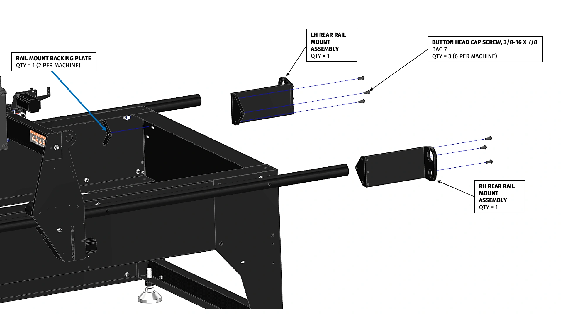
Instructions
WARNING
Failure to leave the Button Head Screws ¼ turn loose in this step before tightening the cinch bolts
can cause your Y-Axis Rail to bend.
- Slide the LH Rear Rail Mount Assembly over the LH Y-Axis Rail until the mounting flange rests against the machine frame. Secure the LH Rear Rail Mount Assembly to the machine frame using 3 BAG 7 screws and one Rail Mount Backing Plate. Leave the screws ¼ turn loose. The rail mount assembly should be able to slide freely with the bolts ¼ turn loose.
-
Repeat Step B1 for the RH Rear Rail Mount Assembly.
Do Not Overtighten Cinch BoltsWARNING: Do not use power tools to tighten cinch bolts. Hand-tool tighten to secure clamp around OD of rail tube.
- Tighten the cinch bolts on each rail mount until they are fully clamped around each Y-Axis rail.
- Tighten the 6 BAG 7 screws that secure the rail mounts to the machine frame.
Materials
Parts
- (2) Front Rail Mount
- (2) Rail Mount Backing Plate
- (1) Machine Frame
Hardware
- (6) BAG 7 BUTTON HEAD CAP SCREW, 3/8-16 X 7/8
- (2) BAG 27 SOCKET HEAD CAP SCREW, 10-24 X 3/4
Tools
- 5/32" HEX
- 7/32" HEX

Instructions
- Slide a Front Rail Mount over the LH Y-Axis Rail until the mounting flange rests against the machine frame. Secure the Front Rail Mount to the machine frame using (3) BAG 7 screws and one Rail Mount Backing Plate. Leave the screws ¼ turn loose.
-
Repeat Step C1 to attach the second front rail mount to the RH Y-Axis rail.
Do Not Overtighten Cinch BoltsWARNING: Do not use power tools to tighten cinch bolts. Hand-tool tighten to secure clamp around OD of rail tube.
- Install and tighten the BAG 27 cinch bolts on each rail mount until they are securely clamped around each Y-Axis Rail.
- Tighten the (6) screws that secure the rail mounts to the machine frame.
9: Limit Switch Strain Relief
Next, we need to reduce the strain on the Limit Switch Cables by following these instructions.
Materials
Parts
- (5) Zip Ties (MISC. PARTS SUB BOX)
Hardware
- (4) BAG 26 SOCKET HEAD CAP SCREW, #8-32 x ⅜”
- (4) BAG 37 P-CLAMP
Tools
- 9/64" HEX

Instructions
- Locate Y-Axis motor Y1 on the lower left-hand side of the gantry upright assembly. Secure Y1 motor cable to gantry upright using (2) BAG 37 P-clamp and (2) BAG 26 socket head cap screws as shown.

Instructions
- Align the Y1 Limit Switch cable downward until it reaches the Y1 motor cable. Secure the limit switch cable to the motor cable use one zip tie. Next, loop the limit switch cable back up so that it follows the Y1 motor cable. Zip tie this limit switch cable to the Y1 motor cable by installing 2 zip ties near the 2 P-clamps as shown.

Instructions
- Identify the Y2 limit switch cable from the loom, the medium length branch of the limit switch tree, and follow it across the X-Axis gantry down to the Y2 motor at the bottom of the right-hand side of the gantry upright assembly. This limit switch has already been installed in a previous section. We suggest laying this cable in the valley of the X-axis motor bracket as shown until the drag chains are installed at a later step.

Instructions
- Repeat Steps outlined in A1 to secure Y2 motor cable and limit switch cable to the corresponding gantry upright assembly.

Instructions
- Locate Z-Axis Motor Assembly and X-Axis limit switch cable on top of X-Axis gantry carriage. To prevent unintentional damage to this wiring, provide strain relief by incorporating a marginal slack loop to the cable and secure it to the Z-axis motor cable with a zip tie just above the P-clamp on the rear of the Z-Axis assembly.
10: Install Water Table
Next, we'll be installing the Water Table onto the machine frame.
Materials
Parts
- (1) Machine Frame
- (2) Water Table Mid-Tray Weldment
- (2) Water Table End-Tray Weldment
Hardware
- (11) BAG 34 SHEET METAL SCREW W/ WASHER, #10 X 3/4
Tools
- DRILL GUN/IMPACT
- 5/16" SOCKET
- AIR COMPRESSOR/VACUUM

Instructions
-
The Crossfire XR Water Table is comprised of four water table sections. Position all four
sections onto the machine frame as shown. Checking around the perimeter of the machine,
make sure that the water table is well centered. Adjust as needed. Now is a good time
to confirm that the machine frame is still square to within 1/8".
Important NoteChips created during the self drilling process can get under the neoprene washers and affect the sealing. Using compressed air to clear any chips under the washers before sinking each screw is recommended.
- Using a nut driver, shoot the 11 BAG 34 self drilling/sealing screws through the pilot holes in the forward Water Table End-Tray Weldment and into the machine frame. Be careful not to shift the water table section from its position, otherwise the alignment of the rest of the water tables will be negatively affected. The remaining sections will be secured in a later step.
Materials
Parts
- (1) Machine Frame (PREVIOUSLY ASSEMBLED)
- (3) Water Table Weldments (PREVIOUSLY PLACED)
- (1) Tube of Marine Sealant Caulk
Hardware
- (45) BAG 5 BUTTON HEAD CAP SCREW, #10-32 X 3/8
- (45) BAG 13 SERRATED FLANGE NUT, #10-32
Tools
- CAULK GUN
- SHOP TOWELS
- ⅛” HEX
- ⅜” WRENCH or SOCKET


Instructions
- Space the water table sections apart approximately 6 inches each on the machine frame.
-
Apply a thick bead of Marine Sealant Caulk to the flange of the end tray that was previously secured to
the machine frame. Using the fasteners shown, secure the first Mid Tray to the End Tray.
Do not excessively tighten the screws to ensure that suitable bondline exists in the joint.
Important Note
Make sure that the when bolting the flanges together that the tray is resting solidly on the machine frame. This is important because in the next step the tray will be screwed down to the machine frame and if there is a large gap between the bottom of the tray and machine frame the sealed joint could be stressed and fail. If slots are vertically misaligned, apply pressure to level the trays when sinking the clamping screws.
It is important to bolt the tray assembly down to the machine frame immediately after sealing the flanges with adhesive.
- Repeat Step B2 for the remaining two joints.
Materials
Parts
- Machine (AS PREVIOUSLY ASSEMBLED)
Hardware
- (27) BAG 34 SHEET METAL SCREW W/ WASHER, #10 X 3/4
Tools
- DRILL GUN w/ 5/16” SOCKET
- AIR COMPRESSOR/VACUUM

Instructions
- Shoot the remaining 27 BAG 34 self drilling screws to secure the water table to the machine frame.
Materials
Parts
- Machine (AS PREVIOUSLY ASSEMBLED)
- Marine Sealant Caulk (REMAINING)
Hardware
- None
Tools
- CAULKING GUN

Instructions
- With the remaining Marine Sealant Caulk, apply a thick bead to the top of the tray seams. Be certain to push the caulk down into this seam as well as the bonding screws and nuts when moving down the flange. This step is important to guarantee a permanent seal of your water table system.
Materials
Parts
- Machine (AS PREVIOUSLY ASSEMBLED)
Hardware
- (2) BAG 39 O-RING, 1/8”
- (2) BAG 16 THIN HEX NUT, 1”-8
- (2) BAG 38 STEEL PIPE FITTING, ¼ NPT
- (2) BAG 43 TANK FITTING, BRASS
Tools
- None

Instructions
- Locate the 1” diameter holes at the bottom of each Water Table End Tray.
-
Complete the following process for installing the drain plugs into each of those holes:
- Slide the BAG 39 O-Ring onto the outer diameter of the BAG 43 Brass Tank Fitting.
- Insert the Brass Drain Plug into the hole in the water table.
- Reach underneath the water table and screw the BAG 16 Thin Hex Nut onto the Brass Tank Fitting and hand tighten.
- Screw the BAG 38 Steel Pipe Fitting into the Brass Drain Plug.
Materials
Parts
- Machine (AS PREVIOUSLY ASSEMBLED)
- (16) Slat Holder
Hardware
- None
Tools
- None

Instructions
- Install the 16 Slat Holders into the slots present in the water table reinforcing ribs. The orientation of the Slat Holders is not important, except that the slots that will later accept the slats must be facing up.
Materials
Parts
- Machine (AS PREVIOUSLY ASSEMBLED)
- (28) Table Slat
Hardware
- None
Tools
- Mallet (if necessary)

Instructions
- Install the 28 Slats into the slots of the slat holders. Use a mallet as necessary to fully seat each slat.
11: Z-Axis Motion
Next, we'll be installing components into the Z-Axis, tramming the Z-Axis, and installing motion components.
Materials
Parts
- Machine (AS ASSEMBLED)
Hardware
- None
Tools
- 3/32" HEX

Instructions
- Remove the Z-Axis Guard by loosening the four Button Head cap screws that secure it to the Z-Axis. Temporarily set the Z-Axis Guard aside.
Materials
Parts
- Machine (AS ASSEMBLED)
Hardware
- None
Tools
- None
Instructions
- Follow Video Instruction to tram the Z-Axis.
Materials
Parts
- Machine (AS ASSEMBLED)
- Z-Axis Guard (PREVIOUSLY REMOVED)
- (1) Torch Slide
- (2) Fixed V-Block
- (2) Floating V-Block
- (1) Thumb Screw
- (1) Torch Mount Clamp Strap
Hardware
- (4) BAG 30 SOCKET HEAD CAP SCREW, ¼-20 X 1.5
- (1) BAG 44 SOCKET HEAD CAP SCREW, ¼-20 X 3/4
- (1) BAG 17 THIN HEX NUT, ¼-20
- (2) BAG 31 SOCKET HEAD CAP SCREW, 10-24 X 7/16
Tools
- 3/32” HEX
- 7/16” WRENCH

Instructions
- Attach the two Fixed V-Blocks to the Torch Slide using theBAG 31 Socket Head Cap Screws. Tighten the screws.
- Attach the Floating V-Blocks to the Fixed V-Blocks using the BAG 30 Socket Head Cap Screws. These screws only need to be hand tightened during this step since they will be tightened later when installing the torch.
- Insert the BAG 44 Socket Head Cap Screw into one of the holes of the Torch Mount Clamp Strap. Screw the BAG 17 Jam Nut onto the screw.
- Place the Torch Mount Assembly into the slot of the Z-Axis Carriage. Screw the BAG 31 screw into the lefthand threaded hole in the Z-Axis Carriage so that Torch Mount Clamp Strap lays on top of the torch mount.
- Insert the Thumb Screw into the other hole of the Torch Mount Clamp Strap and screw it into the Z-Axis Carriage.
- Adjust the clamp strap adjustment screw either in or out until the Torch Mount Clamp Strap lays flat against the torch mount with the Thumb Screw hand tightened. Once the clamp strap adjustment screw is properly adjusted, tighten the BAG 17 jam nut.
- Temporarily reinstall the Z-Axis Guard that was previously removed.
12: X-Axis Motion
CAUTION: DO NOT REMOVE BALL NUTS
CrossFire XR Ball Nuts are pre-installed on the ball screws and should
NEVER be removed from the screws. Removing ball nuts from ball screws will require the replacement
of the ball nut at significant cost.
Materials
Parts
- Machine (AS ASSEMBLED)
- (1) X-Axis Ballscrew Assembly
- (2) Ball Nut Felt Wiper (MISC. BOX)
- (1) Felt Wiper Clamping Plate (MISC. STEEL PARTS BOX)
Hardware
- (1) BAG 42 BUTTON HEAD CAP SCREW, M6 X 6mm X 6mm
- (2) BAG 29 SOCKET HEAD CAP SCREW, M4 X 0.7mm X 16mm
- (2) BAG 28 LOWHEAD CAP SCREW, M4 X 0.7mm X 20mm
Tools
- 4mm HEX
- 3mm HEX
- 2.5mm HEX
- OIL CAN/LITHIUM GREASE

Instructions
- Locate the X-Axis Ballscrew Assembly, which is about half as long as the two Y-Axis Ballscrew Assemblies. The assembly has the ballnut pre-assembled. It is critical that when handling the ballscrew assembly that the ballnut is not allowed to inadvertently unscrew from the ballscrew. The ball screw assembly must be carefully held in a horizontal position to prevent the nut from rotating off the screw. The ballnut is zip tied to the ballscrew, cut this zip tie off and discard.
- Rotate the ballnut until it is roughly in the middle of the ballscrew.
- Press one felt wiper onto each end of the ball screw threads and rotate the wiper along the threads to screw it inward. Continue rotating them until each wiper is in contact with the ballnut.
-
Lubricate your ball nuts with the following procedure:
- Using a suitable lithium grease or lubricating oil, completely coat both felt washers with lubricant.
- Using your grease gun, fill up the oil port hole in the side of the ballnut flange. If you are using grease instead, take a dab of grease and work it into the ball screw threads on both sides of the ball nut felt.
- Screw the BAG 42 button head cap screw into the oil port hole in the ballnut.
- Pass the Felt Wiper Clamping Plate onto the ball screw until it is adjacent to the felt wiper on the flange side of the ballnut. Note: your felt wiper clamping plate may look slightly different than the image but its function is identical.
-
Insert the ballnut into the bore of the ballnut hub such that the felt wiper is clamped between
the hub and the ballnut. Secure the ball nut to the hub using two BAG 29 socket head cap screws
in the two middle holes as shown.
NoteIt may be necessary to cycle the X-Axis Carriage back or forth to facilitate getting the Ballscrew Assembly into position for insertion into the hub.
- Secure the Felt Wiper Clamping Plate using two BAG 28 Lowhead Cap Screws at two opposing holes in the felt wiper clamping plate. Alternating back and forth, snug these two screws down so that the rear ballnut felt wiper is compressed to a thickness of approximately 1/16”. Do not exceed this amount of preload on the wiper or excessive friction can occur.
Materials
Parts
- Machine (AS ASSEMBLED)
- (2) Spherical Rod End Bearing Mount
Hardware
- (4) BAG 33 WASHER, 1 INCH
- (2) BAG 16 THIN HEX NUT, 1”-8
Tools
- None

Instructions
- Starting on the Righthand side of the machine insert the Rod End Bearing Mount into the large hole in the RH Gantry Upright. Secure it using the BAG 33 washers and BAG 16 thin hex nut. Do not tighten the nut, it should be left approximately ¼ turn loose so that it is free to move around the clearance in the hole.
- Repeat Step B1 for the Lefthand side.
!STOP! X-Axis Ball Screw Alignment
CRITICAL: You must watch and understand the following video X-Axis Ball Screw Alignment
before proceeding with assembly. Failure to follow these procedures will lead to binding.
If you have printed out these instructions, do not
continue on with assembly before watching and understanding the following video.
Materials
Parts
- Machine (AS ASSEMBLED)
Hardware
- (2) BAG 2 ROD END BEARING, 1/4
- (2) BAG 23 SOCKET HEAD CAP SCREW, ¼-20 X 5/8
- (1) BAG 1 SOCKET HEAD CAP SCREW, ¼-20 X 1”
Tools
- PADDED PLIERS
- 3/16" HEX

Instructions
- On the Lefthand side of the machine, insert one BAG 2 Rod End Bearing into the bore of the Rod End bearing mount. The bore in the rod end bearing mount has a small step in the opening; be certain to push the bearing down so it is fully seated in the deeper of the two bores.
- Secure it to the end of the ballscrew with the BAG 23 Socket Head Cap Screw. (This should be the shorter of the two cap screws used in this step) Hold the ballscrew with padded pliers to prevent it from rotating while tightening the BAG 23 screw.
- Repeat Step F1 on the Righthand side using a cap screw from BAG 1, except do not tighten the screw that secures the Rod End Bearing. Leave it approximately 1 turn loose.
-
Manually push the X-Axis Carriage over to the Lefthand side of the machine until it has reached
its maximum extent of travel. Tighten the large 1” Hex Nut that was previously installed.
ImportantIt may require considerable hand force to move the carriage as the ballnut and stepper motor is backdriven. Doing so will not cause damage to components.
- Using the outside flats of the Rod End Bearing Mount, tighten the 1" Jam Nut on the inside to secure.
Materials
Parts
- Machine (AS ASSEMBLED)
Hardware
- None
Tools
- 3/16” HEX
- 1 ½” or ADJUSTABLE WRENCH

Instructions
- Manually push the X-Axis Carriage to the maximum Rightward extent of travel.
- Tighten the Socket Head Cap Screw in order to tension the ballscrew. The ballscrew is properly tensioned when deflection at the middle of the ballscrew is limited to approximately ¼” deflection when squeezed with the thumb at the middle of the gantry tube. WARNING: DO NOT OVERTENSION THE BALL SCREW BEYOND THIS DEFLECTION LIMIT. OVERTIGHTENING THIS SCREW CAN RESULT IN DAMAGE TO THE ROD END BEARINGS. If the ballscrew can be rotated when gripping and turning by hand, continue increasing the tension until it cannot be.
- Tighten the large hex nut that secures the Rod End Bearing Mount as performed on the opposite side.
Tension Check
A quick, easy, and effective method to verify that you have sufficient ball screw tension in the
system is to perform the following check:
Grab a 3/16” hex key and position yourself at the tensioning end of the respective ball screw you are working on. All tensioning must be done from the positive ends of either axis (+Y, home position/rear, +X, Y2 side). Make sure the gantry/carriage is positioned at least 6” away from where you are working to allow for adequate clearance for your hand to reach the ball screw. Insert the hex key into the 1” cap screw securing the ball screw; using your other hand, firmly grasp the ball screw to prevent it from rotating. Tension the ball screw by turning the cap screw ½ turn clockwise. The ball screw in your hand should be getting tighter. Repeat the process another ½ turn until proper tension is achieved. If you find that after repeating this process the ball screw is still turning freely in your hand, then there is an issue. Rotation means that the tensioning cap screw has bottomed out and can no longer add any tension to the system.
Under these conditions you can expect there to be binding while jogging above 200IPM because the ball screw is able to rotate and does not have proper tension. To remedy this, add an additional 1” washer next to the outside washer (pictured below) to take up enough space so that the threaded cap screw can now pull the ball screw tighter with proper tension. To do this, loosen the large hex nut securing the rod end bearing mount, then remove the 1” tensioning cap screw. Remove the rod end bearing mount and double up the 1” washer on the outside face. Then carefully reassemble the system and tension and align according to the assembly guide specifications.
![]()
Grab a 3/16” hex key and position yourself at the tensioning end of the respective ball screw you are working on. All tensioning must be done from the positive ends of either axis (+Y, home position/rear, +X, Y2 side). Make sure the gantry/carriage is positioned at least 6” away from where you are working to allow for adequate clearance for your hand to reach the ball screw. Insert the hex key into the 1” cap screw securing the ball screw; using your other hand, firmly grasp the ball screw to prevent it from rotating. Tension the ball screw by turning the cap screw ½ turn clockwise. The ball screw in your hand should be getting tighter. Repeat the process another ½ turn until proper tension is achieved. If you find that after repeating this process the ball screw is still turning freely in your hand, then there is an issue. Rotation means that the tensioning cap screw has bottomed out and can no longer add any tension to the system.
Under these conditions you can expect there to be binding while jogging above 200IPM because the ball screw is able to rotate and does not have proper tension. To remedy this, add an additional 1” washer next to the outside washer (pictured below) to take up enough space so that the threaded cap screw can now pull the ball screw tighter with proper tension. To do this, loosen the large hex nut securing the rod end bearing mount, then remove the 1” tensioning cap screw. Remove the rod end bearing mount and double up the 1” washer on the outside face. Then carefully reassemble the system and tension and align according to the assembly guide specifications.

13: Y-Axis Motion
CRITICAL: Ball Nuts
CrossFire XR Ball Nuts are shipped installed on the ball screws and under no circumstances should
they be removed from the screws during assembly. Removing ball nuts from ball screws will require the replacement
of the ball nut at significant cost.
If your ball screws are shipped with hardware stops (Washers and Buttonhead screws) remove these before continuing with installation.
If your ball screws are shipped with hardware stops (Washers and Buttonhead screws) remove these before continuing with installation.
Materials
Parts
- Machine (AS ASSEMBLED)
- (3) Ballscrew Hanger Tool
- (1) Y-Axis Ballscrew Assembly
- (2) Ball Nut Felt Wiper
- (1) Felt Wiper Clamping Plate
Hardware
- (1) BAG 42 BUTTON HEAD CAP SCREW, M6 X 6mm X 6mm
- (2) BAG 29 SOCKET HEAD CAP SCREW, M4 X 0.7mm X 16mm
- (2) BAG 28 LOWHEAD CAP SCREW, M4 X 0.7mm X 20mm
Tools
- 4mm HEX
- 3mm HEX
- 2.5mm HEX
- OIL CAN/LITHIUM GREASE

Instructions
- Locate one of the Y-Axis Ballscrew Assemblies. The assembly has the ballnut pre-assembled. It is critical that when handling the ballscrew assembly that the ballnut is not allowed to inadvertently unscrew from the ballscrew. The ball screw assembly must be carefully held in a horizontal position to prevent the nut from rotating off the screw. The ballnut is zip tied to the ballscrew, cut this zip tie off and discard.
- Rotate the ballnut until the end that is opposite the mounting flange is approximately 10” from the end of the ballscrew.
- Press one felt wiper onto each end of the ball screw threads and rotate the wiper along the threads to screw it inward. Continue rotating them until each wiper is in contact with the ballnut.
-
Lubricate your ball nuts with the following procedure:
- Using a suitable lithium grease or lubricating oil, completely coat both felt washers with lubricant.
- Using your grease gun, fill up the oil port hole in the side of the ballnut flange. If you are using grease instead, take a dab of grease and work it into the ball screw threads on both sides of the ball nut felt.
- Screw the BAG 42 button head cap screw into the oil port hole in the ballnut.
- Pass the Felt Wiper Clamping Plate onto the ball screw until it is adjacent to the felt wiper on the flange side of the ballnut. Note: Your felt wiper clamping plate may look slightly different than the image but its function is identical.
- Hang the three Ballscrew Hanger Tools onto the Lefthand Y-Axis Rail in the approximate locations shown along the rail.
- Insert the ballnut into the bore of the Lefthand ballnut hub such that the felt wiper is clamped between the hub and the ballnut. With the ballscrew supported by the three hangers, secure the ball nut to the hub using two BAG 29 Socket Head Cap Screws in the two middle holes as shown.
- Secure the Felt Wiper Clamping Plate using two BAG 28 Lowhead Cap Screws at two opposing holes in the felt wiper clamping plate. Alternating back and forth, snug these two screws down so that the rear ballnut felt wiper is compressed to a thickness of approximately 1/16”. Do not exceed this amount of preload on the wiper or excessive friction can occur.
!STOP! Y-Axis Ball Screw Alignment
CRITICAL: You must watch and understand the following video Y-Axis Ball Screw Alignment
before proceeding with assembly. Failure to follow these procedures will lead to binding.
If you have printed out these instructions, do not
continue on with assembly before watching and understanding the following video.
Materials
Parts
- Machine (AS ASSEMBLED)
- (2) Spherical Rod End Bearing Mount
Hardware
- (6) BAG 33 WASHER, 1 INCH
- (2) BAG 16 THIN HEX NUT, 1”-8
- (2) BAG 2 ROD END BEARING, 1/4
- (1) BAG 23 SOCKET HEAD CAP SCREW, ¼-20 X 5/8"
- (1) BAG 1 SOCKET HEAD CAP SCREW, ¼-20 X 1"
Tools
- 3/16” HEX
- 1 ½” or ADJUSTABLE WRENCH


Instructions
- At the front left corner of the machine, slide the BAG 16 Thin Hex Nut and BAG 33 Washer onto the end of the ballscrew.
- Insert the Rod End Bearing Mount into the Front Y-Axis Rail Mount with 1 additional BAG 33 washer in between. Screw the large Thin Nut onto the spherical bearing mount but do not tighten it, leave it approximately ¼ turn loose.
- Insert the Rod End Bearing Mount into the Rear Y-Axis Rail Mount with 2 additional BAG 33 washers in between. Screw the large Thin Nut onto the spherical bearing mount but do not tighten it, leave it approximately ¼ turn loose.
- Back at the front left of the machine, insert the BAG 2 Rod End Bearing into the counterbore of the rod end bearing mount. Note: the bore in the rod end bearing mount has a small step in the opening; be certain to push the bearing down so it is fully seated in the deeper of the two bores. Secure it to the end of the ballscrew using the BAG 23 Socket Head Cap Screw (this should be the shorter of the two cap screws used in this step). Hold the ballscrew with padded pliers to prevent it from rotating while tightening the screw.
- Either by pushing on the gantry upright or by rotating the ball nut, move the gantry as close as possible to the front of the machine until the upright is touching the front left Y-Axis Rail Mount.
- Using the outside flats of the rod end bearing mount, tighten the 1” Jam Nut on the inside to secure.
- At the back left corner of the machine, install the BAG 2 Rod End Bearing and install the BAG 1 Socket Head Cap Screw into the end of the Y-Axis ball screw. Leave the screw approximately ¼ turn loose. This will be tightened in a later step.
Instructions
- Repeat previous Steps A1-A8 and B1-B7 to install the Righthand Ballscrew and Ballnut.
Materials
Parts
- Machine (AS ASSEMBLED)
- (2) Spherical Rod End Bearing Mount
Hardware
- (6) BAG 33 WASHER, 1 INCH
- (2) BAG 16 THIN HEX NUT, 1”-8
- (2) BAG 2 ROD END BEARING, 1/4
- (1) BAG 23 SOCKET HEAD CAP SCREW, ¼-20 X 5/8"
- (1) BAG 1 SOCKET HEAD CAP SCREW, ¼-20 X 1"
Tools
- 3/16” HEX
- 1 ½” or ADJUSTABLE WRENCH

Instructions
- Remove the three ballscrew hangers and manually push the gantry by apply pressure to the middle of the X-Axis gantry tube so that the gantry reaches the maximum rearward extent of travel. Reinstall the three ball screw hangers in the approximate locations shown to support the Lefthand ballscrew.
- Tighten the socket head cap screw at this end in order to tension the ballscrew. The ballscrew is properly tensioned when deflection at the middle of the ballscrew is limited to approximately 3/8” deflection when pushed by hand. WARNING: DO NOT OVERTENSION THE BALL SCREW BEYOND THIS DEFLECTION LIMIT. OVERTIGHTENING THIS SCREW CAN RESULT IN DAMAGE TO THE ROD END BEARINGS. If the ballscrew can be rotated when gripping and turning by hand, continue increasing the tension until it cannot be.
- Tighten the large hex nut that secures the rod end bearing mount as performed at the opposite end of the screw.
- Repeat Steps 1-3 for the Righthand ballscrew.
Tension Check
A quick, easy, and effective method to verify that you have sufficient ball screw tension in the
system is to perform the following check:
Grab a 3/16” hex key and position yourself at the tensioning end of the respective ball screw you are working on. All tensioning must be done from the positive ends of either axis (+Y, home position/rear, +X, Y2 side). Make sure the gantry/carriage is positioned at least 6” away from where you are working to allow for adequate clearance for your hand to reach the ball screw. Insert the hex key into the 1” cap screw securing the ball screw; using your other hand, firmly grasp the ball screw to prevent it from rotating. Tension the ball screw by turning the cap screw ½ turn clockwise. The ball screw in your hand should be getting tighter. Repeat the process another ½ turn until proper tension is achieved. If you find that after repeating this process the ball screw is still turning freely in your hand, then there is an issue. Rotation means that the tensioning cap screw has bottomed out and can no longer add any tension to the system.
Under these conditions you can expect there to be binding while jogging above 200IPM because the ball screw is able to rotate and does not have proper tension. To remedy this, add an additional 1” washer next to the outside washer (pictured below) to take up enough space so that the threaded cap screw can now pull the ball screw tighter with proper tension. To do this, loosen the large hex nut securing the rod end bearing mount, then remove the 1” tensioning cap screw. Remove the rod end bearing mount and double up the 1” washer on the outside face. Then carefully reassemble the system and tension and align according to the assembly guide specifications.
![]()
Grab a 3/16” hex key and position yourself at the tensioning end of the respective ball screw you are working on. All tensioning must be done from the positive ends of either axis (+Y, home position/rear, +X, Y2 side). Make sure the gantry/carriage is positioned at least 6” away from where you are working to allow for adequate clearance for your hand to reach the ball screw. Insert the hex key into the 1” cap screw securing the ball screw; using your other hand, firmly grasp the ball screw to prevent it from rotating. Tension the ball screw by turning the cap screw ½ turn clockwise. The ball screw in your hand should be getting tighter. Repeat the process another ½ turn until proper tension is achieved. If you find that after repeating this process the ball screw is still turning freely in your hand, then there is an issue. Rotation means that the tensioning cap screw has bottomed out and can no longer add any tension to the system.
Under these conditions you can expect there to be binding while jogging above 200IPM because the ball screw is able to rotate and does not have proper tension. To remedy this, add an additional 1” washer next to the outside washer (pictured below) to take up enough space so that the threaded cap screw can now pull the ball screw tighter with proper tension. To do this, loosen the large hex nut securing the rod end bearing mount, then remove the 1” tensioning cap screw. Remove the rod end bearing mount and double up the 1” washer on the outside face. Then carefully reassemble the system and tension and align according to the assembly guide specifications.
14: Install Cable Trays & Hardstops
Materials
Parts
- Machine (AS ASSEMBLED)
- (2) Y-Axis Cable Tray
Hardware
- (9) BAG 13 SERRATED FLANGE NUT, 10-32
- (9) BAG 4 BUTTON HEAD CAP SCREW, 10-32 X 1/2
Tools
- ⅜” WRENCH or SOCKET
- ⅛” HEX

Instructions
- Attach the Y-Axis Cable Trays to the Lefthand side of the machine frame using the fasteners shown.
- Attach the Y-Axis Cable Trays to eachother using the fastener shown.
Materials
Parts
- Machine (AS ASSEMBLED)
- (1) X-Axis Cable Tray
Hardware
- (4) BAG 6 BUTTON HEAD CAP SCREW, 10-24 X 1/2"
Tools
- ⅛” HEX

Instructions
- Attach the X-Axis Cable Tray to the gantry uprights using the fasteners shown.
Materials
Parts
- Machine (AS ASSEMBLED)
Hardware
- (1) BAG 14 SERRATED FLANGE LOCKNUT, 10-24
- (1) BAG 35 HEX HEAD CAP SCREW, 10-24 X 2"
Tools
- None

Instructions
- Insert the BAG 35 screw with BAG 14 nut into the tapped hole in the Righthand Gantry Upright. This is a Hard Stop and will be fine adjusted in a later step. Leave the nut loose for now.
Materials
Parts
- Machine (AS ASSEMBLED)
Hardware
- (2) BAG 14 SERRATED FLANGE LOCKNUT, 10-24
- (2) BAG 35 HEX HEAD CAP SCREW, 10-24 X 2"
Tools
- None

Instructions
- Insert the BAG 35 screw with BAG 14 nut into the tapped hole in the Righthand rear Y-Axis Rail Mount. This is the Righthand Limit Switch Stop and will be fine adjusted in a later step. Leave the nut loose for now.
- Repeat Step 1 for the Lefthand side.
Materials
Parts
- Machine (AS ASSEMBLED)
- X-Axis Limit Switch Stop
Hardware
- (1) BAG 24 SOCKET HEAD CAP SCREW, 10-24 X 1/2"
Tools
- 5/32” HEX

Instructions
- Attach the X-Axis Limit Switch Stop to the to of the Lefthand gantry upright using the BAG 24 Socket Head Cap Screw.
Materials
Parts
- Machine (AS ASSEMBLED)
- Y-Axis Drag Chain Mount
Hardware
- (2) BAG 4 BUTTON HEAD CAP SCREW, 10-32 X ½"
- (2) BAG 13 SERRATED FLANGE NUT, 10-32
Tools
- ⅜” WRENCH or SOCKET
- ⅛” HEX

Instructions
- Attach the Y-Axis Drag Chain Mount to the Lefthand side of the X-Axis Cable Tray using the fasteners shown.
15: Install Electronics & Control Computer
Materials
Parts
- Machine (AS ASSEMBLED)
- (1) CrossFire XR Electronics Enclosure
Hardware
- (4) BAG 41 RUBBER ISOLATION MOUNT
- (4) BAG 12 SERRATED FLANGE NUT, M6
Tools
- 10mm WRENCH

Instructions
-
Locate the Crossfire XR Electronics Enclosure and install the four BAG 41 Isolation Mounts into
the 4 panel nuts on the back on the enclosure. Use pliers gripping on the rubber to seat them into
the nuts but do not overtighten.
Do NOT OvertightenWARNING: Do not use power tools to tighten Serrated Flange Nuts. Hand tighten to secure only.
- Locate the four hole pattern in the Left Corner of the frame at the front of the machine. Insert the isolation mount studs into the holes and secure them hand-tight them to the frame using the four BAG 12 Serrated Flange Nuts.
Materials
Parts
- Machine (AS ASSEMBLED)
- (1) Computer Mount
Hardware
- (4) BAG 3 BUTTON HEAD CAP SCREW, ¼-20 X 3/4
- (4) BAG 9 SERRATED FLANGE LOCKNUT, ¼-20
Tools
- 7/16” WRENCH or SOCKET
- 5/32” HEX

Instructions
- Attach the Computer Mount to the front left corner of the machine frame using the fasteners shown.
Materials
Parts
- Machine (AS ASSEMBLED)
- (1) Touchscreen Pivot Bracket
Hardware
- (4) BAG 21 SOCKET HEAD CAP SCREW, ¼-20 X 1/2"
- (4) BAG 32 WASHER, ¼"
- (4) BAG 9 SERRATED FLANGE NUT, ¼-20
Tools
- 3/16” HEX
- 7/16” WRENCH or SOCKET

Instructions
- Attach the Touchscreen Pivot Bracket to the computer mount using the fasteners shown.
Materials
Parts
- Machine (AS ASSEMBLED)
- (1) Touchscreen VESA Mount
- (1) MC4000 Machine Controller PC
Hardware
- (2) BAG 21 SOCKET HEAD CAP SCREW, ¼-20 X 1/2"
- (2) BAG 32 WASHER, ¼"
- (2) BAG 9 SERRATED FLANGE NUT, ¼-20
- (2) BAG 20 SOCKET HEAD CAP SCREW, M3 X 0.5MM X 6MM
Tools
- 3/16” HEX
- 2.5mm HEX
- 7/16” WRENCH or SOCKET

Instructions
- Attach the Touchscreen Vesa Mount to the Touchscreen Pivot Bracket using the fasteners shown. The angle of the mount is adjustable to any angle between horizontal and vertical. A 45 degree mounting angle is a good initial setting and can be fine tuned later.
- Attach the MC40000 Machine Controller PC to the Touchscreen VESA Mount using the fasteners shown.
Materials
Parts
- Machine (AS ASSEMBLED)
- (1) Touchscreen Monitor
Hardware
- (4) BAG 19 SOCKET HEAD CAP SCREW, M4 X 0.7MM X 6MM
Tools
- 3mm HEX

Instructions
- Attach the Touchscreen Monitor to the Touchscreen VESA Mount using the fasteners shown.
16: Install Stickers, Caps, Adjustments
Materials
Parts
- Machine (AS ASSEMBLED)
- (1) Langmuir Systems Gantry Sticker
- (1) Machine Plate Sticker
- (1) Gantry Warning Sticker
Hardware
- None
Tools
- None

Instructions
- Attach the three stickers to the machine in the locations shown.
Materials
Parts
- Machine (AS ASSEMBLED)
Hardware
- (4) BAG 40 2” PLASTIC TUBE CAP
Tools
- Mallet (if necessary)

Instructions
- Insert one BAG 40 Y-Axis Rail Tube Cap into each open end of both Y-Axis Rails. Use a mallet as needed to fully seat each tube cap into the end of the tubes.
Materials
Parts
- Machine (AS ASSEMBLED)
Hardware
- None
Tools
- None
Instructions
- Follow Video Instruction to set up Limit Switch Hard Stops.
Limit Switch Hard Stop

17: Wiring & Cable Routing
Materials
Parts
- Machine (AS ASSEMBLED)
- (1) IHS Cable
- (11) Zip Tie
- (1) X-Axis Drag Chain
- (1) Y-Axis Drag Chain
Hardware
- (1) BAG 26 SOCKET HEAD CAP SCREW (SHCS), #8-32 x ⅜”
- (16) BAG 15 #8-32 FLANGE NUT
- (16) BAG 25 SOCKET HEAD CAP SCREW #8-32 x ½”
- (1) BAG 37 P-CLAMP
Tools
- Small Flat-head Screwdriver
- 11/32” Wrench or Socket
- 3/16” Hex Key
- 9/64” Hex Key
- 3/32” Hex Key

Instructions
- Locate the X-Axis Drag Chain. It should be the shorter of the two drag chains. Lay it down in the X-Axis Cable Tray and orient it so that the chain is curling in the upward direction. Next, Locate the 4 bolt pattern in the center of the X-axis Cable Tray and position one end of the drag chain so that it lines up to this bolt pattern. Install (4) BAG 25 SHCS into this bolt pattern from the side of the drag chain.
- Next, using a 9/64” Hex Key inserted through the holes in the top of the drag chain, fasten the drag chain to the cable tray using (4) BAG 15 flange nuts as shown.

Instructions
- In a similar fashion to installing the X-Axis Drag Chain, position the Y-axis Drag Chain in the Y-axis Cable Trays with the chain curling in the upward direction. In the front section of the Y-axis Cable Tray, locate the 4 bolt pattern that is closest to the center tray support bracket that joins the two tray sections and place one end of the chain here. Install (4) BAG 25 SHCS into this bolt pattern from the side of the drag chain.
- Next, using a 9/64” Hex Key inserted through the holes in the top of the drag chain, fasten the drag chain to the cable tray using (4) BAG 15 flange nuts as shown.

Instructions
- After securing the drag chains to the trays, carefully remove only the top links from each drag chain with a small flat-head screwdriver by inserting the tip into the front slot on both sides and pressing the handle downward until the link is popped out. Then carefully remove the loosened links by hand and set aside.

Instructions
- Using the 3/32” hex key, remove the Z-axis guard cover and cable by loosening the 2 button head screws on each side and pulling the guard straight out. The guard can be set aside for now.
- Identify the 2 red anodized torch clamps and use the 3/16” hex key to loosen the stainless SHCS evenly to provide an adequate opening for the torch. Next, move the gantry along the Y-Axis by applying pressure uniformly along the gantry. Carefully adjust the gantry forward or back to center the torch clamps over the nearest table slat edge.

Instructions
- Identify the lead screw inside the Z-Axis Assembly and spin the coupler to manually lower the Z-Axis slide until the bottom edge of the slide is approximately ¼”above the bottom flange of the Z-Axis base. This helps ensure that you are getting the full Z-Axis travel during operation.
- Load your Plasma Machine Torch into the clamps and allow the torch nozzle to rest on the bed slat below. Uniformly tighten the torch clamps to secure the torch inside the assembly.
- Replace guard cover and tighten the button head screws.

Instructions
- From the Miscellaneous parts box, locate the IHS Cable with attached blade connectors. Fasten the IHS Cable to the Z-Axis base with (1) BAG 37 P-clamp and (1) BAG 26 SHCS as shown.
- With the cable secured, connect the two male blade connectors on the IHS Cable to the corresponding female blade connectors sticking out of the Z-axis guard. The IHS cable wires do not transmit polarity so it is not important which side is connected to the red or black cable running to the unit.
- Visually confirm a solid connection is made to avoid connectivity issues downstream. The IHS cable should have a strain relief loop and stick up in the air as shown.
IHS & Torch Cable Strain Relief
Refer back to this GIF for how the strain relief loops should function in the IHS and Torch cable when jogging up and down.

Instructions
- With all the cables now installed, refer to the WIRE ROUTING TABLE, below, to begin staging the wires into the 3 distinct travel groups defined in the chart. Each set of cables will traverse a unique path until they collect at the Y-axis drag chain bracket for final feeding into the Y-axis Drag Chain. Be sure to identify each cable with colored tape or simple label near the connector end to simplify port location designation.
Wire Routing Table
| X & Y-Axis Drag Chains | X-Axis Tray & Y-Axis Drag Chain | Y-Axis Drag Chain Only |
|---|---|---|
| Z-Axis Motor Cable | Y2 Motor Cable | Y1 Motor Cable |
| X-Axis Limit Switch Cable | Y2 Limit Switch Cable | Y1 Limit Switch Cable + Full Cable |
| X-Axis Motor Cable | ||
| Machine Status Cable | ||
| IHS Cable | ||
| Plasma Torch Lead |


Instructions
-
With each set of cables grouped and accounted for according to the wiring table above, bundle the cables
together at the rear of the Z-Axis with zip ties using the following three steps:
- 1. Use a Zip Tie to bundle together the Machine Status Cable, IHS Cable, Z-Axis Limit Switch Cable, and Z-a\Axis motor Cable as shown.
- 2. Take this bundle and run it parallel to the X-axis towards the X-Axis motor. Use a Zip Tie to attach this bundle to the X-Axis motor cable where the cable exits the rear of the motor as shown.
- 3. Route the bundle into the X-axis Drag Chain opening and zip tie the bundle to the plasma torch lead and the X-Axis motor cable.

Instructions
- It is important to create a strain relief loop in the plasma torch lead to allow the plasma torch to move up and down without inhibition. Failure to do this can cause issues with the Initial Height Sensing (IHS) if the torch can bind during travel. We recommend orienting the plasma torch strain relief as shown so that the torch lead exits the Z-Axis guard in a vertical orientation. In the event that your torch lead wants to lay down to one side, we recommend using a zip tie at the X-axis drag chain opening to secure the torch lead to the drag chain to allow the torch lead to stay in the vertical position as shown.

Instructions
- Lay the tied cables across the X-Axis drag chain mounting bracket.
- Next, take the loose end of the X-Axis drag chain and feed the cable bundle through the open end. Take one of the removed links and reinstall it onto the end of the chain at the bottom in order to hold the wire bundle inside the chain end.
- Secure the chain to the mounting bracket over the wires using (4) BAG 25 SHCS and (4) BAG 15 Flange Nuts.
- Replace the remaining drag chain links while pulling the bundle taught through the drag chain until the
cables are exiting the end of the drag chain into the X-Axis Cable Tray.
![]()


Instructions
- Neatly secure all cables now spanning the X-Axis Cable Tray using zip ties through the hole patterns in the tray.
- Next, collect the Y1 motor and limit switch cables and bundle all cables together at the Y-Axis drag chain mount with a zip tie. Pass the bundle over the bracket to be staged for the Y-Axis chain.

Instructions
- Mount the Y-Axis drag chain over the cables to the bracket as shown. Pass the cables through the chain and reinstall the remaining chain links as done previously on the X-axis Drag Chain. Secure the drag chain end to the Y-Axis mounting bracket using (4) BAG 25 SHCS and (4) BAG 15 Flange Nuts.

Instructions
- With all cables previously identified and labeled, simply connect each cable to the corresponding connector port on the back side of the electronics box. Remove any additional slack from the cables by pulling them taught at the box and zip tying the excess length looping back to the Y-Axis carrier tray as shown.
18: Control Setup
With the table assembled and all connections made to the electronics box, proceed by connecting the user interface touch screen and controller computer to the CNC electronics box.
Materials
Parts
- Machine (AS ASSEMBLED)
- (2) Snap-on Choke (Misc. Parts Sub Box)
- (3) Zip Tie (Misc. Parts Sub Box)
- (1) AC Power Adapter (Touchscreen Box)
- (1) Short USB Cable (Touchscreen Box)
- (1) HDMI Cable (MC4000 Box)
- (1) AC Power Adapter (MC4000 Box)
- (1) CNC Electronics Power Cord (Controller Computer & ATHC Box)
- (1) Long USB Cable (Controller Computer & ATHC Box)
- (1) USB Isolator Dongle
- (1) Wireless Jog Pendant (Controller Computer & ATHC Box)
- (1) USB Charging Cable (Controller Computer & ATHC Box)
Hardware
- None
Tools
- None

Instructions
- Locate the HDMI cable. Connect one end to the input on the touchscreen and the other to the output on the controller computer module. Also connect the AC power adapter to the screen and nearby power source.
- Next, inside the touchscreen box, locate the shorter USB cable and connect it to the designated ports on the touchscreen and computer module. Connect the appropriate AC adapter from the MC4000 Computer Box to the module and power source.
- From the Controller Computer & ATHC Box, locate the longer USB cable. From the Misc. parts box, find the two EMI chokes. Connect the chokes to each end of this cable as shown by looping the ends of the cable through the chokes and snapping them closed. These chokes help to eliminate any EMI which may otherwise create interference with extremely sensitive electrical components inside the Electrical Components box.

Instructions
- Your CrossFire XR ships with a USB Isolator Dongle in order to provide enhanced EMI and EMC protection for data communications between the controller computer and the CNC Electronics Enclosure. To install, simply plug the male USB end of the dongle into the bottom facing USB port next to the HDMI cable as shown in the image above. Your system should now function as normal with maximum protection at both ends of the USB cable (the XR motion controller board includes a USB isolator circuit on the board itself).

Instructions
- With the chokes and USB Isolator properly installed, connect the PC module (with Isolator) to the USB input port at the front of the CNC electronics box. With all cables now installed, neatly secure them to the touchscreen mount stand with zip ties through both sets of predrilled holes as shown.

Instructions
- From the Computer Controller & ATHC box, remove the Wireless jog pendant (keypad/mouse controller). Remove the rear cover to expose the rechargeable battery and wireless USB adapter. Install the adapter in the USB slot on the PC module for wireless control capability. Take note of the “ON/OFF” switch position at the top of the controller. The switch must be in the “ON” position during use and should be turned off when stored to extend battery life. The jog pendant also functions as a mouse touchpad using your fingers as shown in the diagram.

Instructions
- Turn the touchscreen on by pressing the power button at the rear of the touchscreen. Next, locate the power ON button on the side of the controller PC as shown. In order to turn the PC on, press this button once and watch the small blue LED in the top corner of the computer as shown. This LED will flash on briefly then turn off. When the LED turns off, press the power button again to boot up the computer. The LED will stay solid indicating the computer is on.
- Proceed to the next section to set up your MC4000 Control Computer.
MC4000 Control Computer Setup
Your MC4000 Windows 10 Control Computer comes ready to go with all of the hardware you need to run your CrossFire XR CNC Machine but there are a few software setup tasks required before you are ready to cut.
MC4000 Applications
The MC4000 PC is designed to run FireControl to control your CrossFire Machine. It is not intended to do any
additional CAD, CAM, or design work. No applications other than FireControl should be installed or run concurrently.
Please Note: the MC4000 may be vulnerable to damage caused by electronic pulses generated during welding activities in close proximity to its electronics. Langmuir Systems highly recommends maintaining a distance of 10-20 feet between the welding arc and the MC4000 electronics. If welding tasks are scheduled near or around the MC4000 computer, we advise either powering it down or adequately shielding it to prevent any potential damage.
Please Note: the MC4000 may be vulnerable to damage caused by electronic pulses generated during welding activities in close proximity to its electronics. Langmuir Systems highly recommends maintaining a distance of 10-20 feet between the welding arc and the MC4000 electronics. If welding tasks are scheduled near or around the MC4000 computer, we advise either powering it down or adequately shielding it to prevent any potential damage.
-
Connect your MC4000 and HD Touchscreen
Your MC4000 PC should be connected to power and the HD touchscreen monitor via HDMI and USB. The included HD Touchscreen's touch capability requires USB connection to the MC4000. The MC4000 must also be connected to the CrossFire XR Electronics via USB. If you wish to utilize the wireless keyboard pendant you may also plug in the USB dongle at this stage.
Create your Windows User Account and Complete Windows SetupBoot up your MC4000 and you will be presented with the standard Windows Out-Of-Box Experience and user creation as with any new Windows PC. During this proccess you will be asked to accept the Windows EULA, select keyboard layouts and to connect to the internet.
Our recommended setup procedure for the MC4000 is to use an offline user account. This is a user account that is not connected to an online Microsoft account. To do this, when prompted to connect to WiFi click the ‘Skip Step’ button in the lower corner. You can of course use an online Microsoft user account if the location of your CrossFire CNC has consistent internet access.
You will create a user name, password, and account recovery hints.
![]()
It is also recommended that you do not sign up for or agree to options for Office 365, Cortana, or any of the privacy settings as these can take up valuable system resources.
![]() Connect to the Internet
Connect to the InternetOnce your Windows account is created and you have set up your PC with a user account, you will need to connect to the internet. In order to download the software and latest driver updates necessary for operation, you will need to connect your PC to WiFi or to a wired connection via the ethernet port.
![]() Download and Install the latest Graphics Driver
Download and Install the latest Graphics DriverFirst, install the latest graphics drivers for the MC4000 to both enable the visualizer and achieve the best performance.
- Click the following Hyperlink: Graphics Driver Download from Intel. Or navigate to the Downloads Page under the Support Menu.
- Download the Recommended Driver file directly from Intel. It will be about 1 GB.
- Run the downloaded file. (You may need to authorize Intel, Inc to make changes to your computer.) There may be a long pause while Windows scans this large file for malware.
-
Choose ‘Begin Installation’.
![]()
-
Choose ‘Next’ to verify that a driver update is needed.
![]()
-
Choose ‘Start’ to proceed with installation of Drivers.
![]()
- This process should take about 10 minutes and will require the computer to reboot. You will likely see the screen flicker.
Install FireControl USB LS-THC DriverNext, you will need to install the LS-THC Driver to connect the THC to your MC4000.
- Navigate to Langmuir Systems Downloads page to download or download the FireControl USB THC (CH340) Driver directly.
-
Unzip this file by selecting the file and choosing to Extract All.
![]()
-
Double click on the extracted .EXE file to install. You may have to allow Jiangsu Qinheng Co to make changes on your computer.
![]()
-
Select the INSTALL option in the Driver Setup.
![]()
Download FireControlDownload the latest version of FireControl using the ‘Download FireControl’ Shortcut on your MC4000 Desktop or by navigating to the Langmuir Systems Downloads page.
![]()
- Install following the FireControl Installer instructions.
Disable the Touch FeedbackThis is a Windows setting that will make the FireControl experience with your CrossFire CNC better by eliminating the hover square over your touch point on your HD Touchscreen while continuously jogging.
-
Go to Control Panel.
![]()
-
Select Pen and Touch Settings. You may need to change the View By to either large or small icons to see Pen and Touch.
![]()
-
Deselect ‘Show visual feedback when touching the screen’ option in Pen and Touch settings.
![]()
- Select OK.
Verify Sleep SettingsYour MC4000 Control Computer should be acting as a kiosk and should never ‘go to sleep’. Verify all Sleep settings are set to ‘Never’ in Settings > Power & Sleep.
![]()


Initial XR Run
WARNING: Avoiding Electrical Interference
EMF interference from your plasma cutter can interfere with the CrossFire CNC Electronics.
To avoid this before cutting, make sure that:
- Your plasma cutter is as far away from your CNC machine as possible.
- Your plasma cutter's work clamp is attached at the back most slat.
- There are no loops in your plasma cutters wor clamp cable or plasma lead cable when sitting on the ground.
- Both included Ferrite Chokes are installed and looped in the ends of the USB cable as shown above.
1
Install FireControl
Download the latest version of FireControl by visiting our website and following the onscreen prompts to install FireControl to the controller computer. If you do not have internet setup on your computer, you will need to save the .MSI file onto a thumb flash drive and then install this from the flash drive. Use the FireControl Guide to learn more about the software used to control your XR.
2
Verify Connections and Turn On XR
Verify that all connections to the CNC electronics box are correct. If your machine is touching any of the X, Y1, or Y2 limit switches, manually push the machine of the switches so that all limit switches are open. Next, turn on the machine by flipping the power switch at the rear of the electronics box. You should hear power transmit to the stepper motors and a light humming noise from the motors is normal.
3
Start FireControl
Open FireControl software. The 'CrossFire XR' Machine and 'LS-THC XR' Height Control device should automatically connect in the top right of the screen. Verify that the machine USB cable is plugged into both the computer and the electronics box.
4
Home the XR
Before jogging the machine, a homing operation will need to be performed. Before homing, use the Jog Buttons on the touchscreen or the wireless jog pendant to Jog the Z-Axis up so that it clears the slat table surface. This is to ensure that your torch will not hit anything when homing to the back left of the machine. Once everything is clear, press the Homing button in FireControl. Note: If an alarm is popped during homing when the Y1 and Y2 limit switches are triggered it is possible that your gantry had a substantial racking before homing. Perform the homing procedure again if this is the case. Another cause for the alarm is that your Y1 and Y2 stepper motor plugs are switched at the electronics box. Y1 should control the motor on the left side of the gantry and Y2 should be on the right side.
5
Download XR Break-In
Download the XR Break-in Program from our Downloads page. This will be the first program you run on your XR to wear in the rails and make sure everything is fucntioning properly.
6
Run the XR Break-in
After downloading the XR's Break-in program and successfully homing, load the 'CrossFire XR Break-in Program' previously downloaded. Click the 'Fit Machine' button in the lower left hand of the visualizer to display the machine bounding box. At this point you should see the break-in program loaded over the gray rectangle that displays the machine travel bounds. Note: if you don't see the machine bounds click the 'Show Machine' Toggle. Click the 'Start' button to start the Break-In Program.
Plasma Cutter Wiring
Wiring your specific Plasma Cutter to the CrossFire XR is easy. Continue to the correct guide below.
Razorweld 45 Plasma Cutter

The Razorweld Razorcut 45 Plasma Cutter & Machine Torch purchased with your Crossfire XR comes with integrated plug and play ports and connector cables to provide the fastest and easiest set up procedure. The left port controls torch firing while the right provides divided voltage input data for the LS-THC VIM module.
From inside your Razorweld box, find the longer of the two cables and connect one end to the left side port at the front of your Razorweld machine. The other end should plug into the corresponding port on the electronics enclosure marked “TORCH ON/OFF.”
Next, locate the LS-THC Wiring & Accessories box and find the THC output cable and the voltage input module (VIM).Then locate the double-sided velcro fastener tape. Next, apply one half of the double-sided velcro to the broad side of the plasma cutter close to the ports and the other to the back of the VIM.
With the VIM now velcroed to the Razorweld45, grab the shorter cable from inside the Razorweld box and plug one end into the right side port at the front of the Razorweld machine. The other end of this cable should plug into the VIM box DIV INPUT socket. Next, connect the THC output cable to the DIV output on the VIM and the other end to the “THC” port on the CNC electronics box. For more detailed information, please refer to our LS-THC Guide here.
Hypertherm Plasma Cutter

If you have a Hypertherm Plasma cutter we recommend purchasing an XR compatible plug-and-play connector cable from our online store for the easiest possible installation. This uses one cable to connect your Hypertherm to both the Torch Firing ON/OFF port on the CNC electronics Box and also the DIV INPUT socket on the VIM module for THC functionality. Please note: you must have a Hypertherm Plasma cutter with Machine Torch AND CPC port to use this cable.
If your Hypertherm does not have the CPC port or you want to make your own cable for the CPC port, the LS-THC Wiring & Accessories box does include a pigtail coupling system that allows you to connect your VIM directly to your Hypertherm CPC port or to Raw Voltage inside the cutter. The Torch Firing Accessories bag in the Misc. Sub Box also includes a Torch Firing Pigtail Cable that can be hooked up to the CPC port for torch firing (or manually installed to the trigger wires inside the plasma cutter using the T-TAP connectors).
For more detailed information on how to manually wire your Hypertherm Cutter for THC usage, please refer to our LS-THC Guide here. For manually wiring the plasma cutter for Torch Firing, please refer to our Plasma Cutter Wiring Guide here.
Other Plasma Cutters
You can also hook up any plasma cutter on the Approved Plasma Cutter List to use with the CrossFire XR Plasma Machine. The pigtail cables that come included with each machine allow the user to manually hook up the cutter for both automatic torch firing as well as connecting to the THC module for automatic height control (with either divided or raw input voltage).
For more detailed information on how to manually wire your Hypertherm Cutter for THC usage, please refer to our LS-THC Guide here. For manually wiring the plasma cutter for Torch Firing, please refer to our Plasma Cutter Wiring Guide here.
What's Next
1
Install Design Software
View the Software Workflow and follow along our Fusion 360 CAD and CAM guide to start designing parts!
2
Learn more about LS-THC
Learn more about the LS-THC unit and your XR with the Torch Height Control Guide.
3
Make your First Cuts
Start cutting out parts with your XR!
Legal
Warranty
All Langmuir Systems products are covered by a 12 month limited warranty on hardware and 6 month limited warranty on electronics. The terms of the warranty are listed below:
- Warranty benefits only apply to the original purchaser and expire if goods are resold. You must provide proof of purchase and your machine's unique serial number (if applicable) via email before a warranty claim may be filed.
- The buyer has 30 days after delivery to report and request to receive any missing items. Langmuir Systems will ship the missing items to the buyer within 10 business days. Langmuir Systems has the right to refuse replacement of items to any buyer that it suspects may not be truthful. The buyer is responsible for the replacement of any missing items after the 30 day period expires.
- Langmuir Systems guarantees the goods received to be defect free for a period of 12 months for
mechanical hardware and 6 months for electronics. Items that meet the following conditions will be
replaced free of charge:
- Items that are received in defective and unusable condition.
- Items that become defective and unusable after use as a result of a manufacturing, design, or material defect.
- The warranty does not cover the following types of defects:
- Defects that do not negatively affect the items functionality. Examples may include scratches, dings, dents, and surface abrasions.
- Defects that are caused by improper assembly.
- Defects that are caused by improper use.
- Defects that are caused by inadequate or incorrect routine maintenance.
- Defects that are caused by improper storage of the item or exposure of the item to the elements.
- Defects that are caused by normal wear and tear.
- If a damaged or defective item is covered by the warranty, Langmuir Systems reserves the right to request that the defective item be shipped back before supplying a replacement. Langmuir Systems will supply a shipping label to cover the expense of the return shipment. The Buyer is responsible for handling and packaging. Langmuir Systems will ship either a refurbished or brand new replacement item within 5 business days of receiving the defective item.
Return and Refund Policy
All products sold directly by Langmuir Systems are eligible for return and refund. The terms of the return and refund policy are listed below:
- Only the original buyer of the item is eligible to return the item for a refund. Proof of purchase is required in order to be eligible for a refund.
- A return must be requested within 30 calendar days following the delivery of the item. Return requests after the eligibility period will be denied.
- The buyer is responsible for all shipping and handling costs associated with shipping the item back.
- Items that are eligible for return must meet all of the following requirements:
- The item must be in unused condition.
- The item must be free of defects.
- The item must be received in the original packaging.
- Langmuir Systems will inspect the item within 5 business days of receiving it. The buyer will be informed if it passes inspection and thus is eligible for a refund.
- If Langmuir Systems concludes that the item meets the refund eligibility requirements, a refund for the original transaction amount minus a 20% restocking fee will be issued to the Buyer within 5 business days following the completion of the inspection.
- 'In person' returns require permission from Langmuir Systems in advance.
- All purchases are subject to a non-refundable 2.4% merchant transaction fee.