DANGEROUS HIGH VOLTAGE PRESENT INSIDE ELECTRONICS ENCLOSURE: In order to install the THC module into the motion control board, the electronics enclosure cover needs to be removed. Make certain to completely disconnect the power cord from the power inlet rocker socket on the front of the electronics enclosure before proceeding.
LS-THC Guide
Introduction
When operating a CNC Plasma table, it is important to maintain a fixed cutting height of the torch throughout the cutting process in order to achieve good cut quality. While the plasma torch tip-to-plate distance can be automatically set at the start of a cut by the Initial Height Sensing (IHS) switch, it is difficult to maintain this exact height throughout the cut. Remember that a typical plasma cutting torch tip-to-plate distance is only 0.060” and that normal sheet metal and plate stock are not perfectly flat. In addition, the heat generated during the cutting process can cause warpage in the material which makes it even more difficult to maintain this stand-off height. If the torch gets too close to the material during cutting it can cause premature wear to the cutting nozzle and also result in more backside dross. Even worse, the torch can crash into the material if the plate is warped enough over a longer cut which consumes some of the 0.060” starting cut height. Conversely, if the torch pulls too far away from the material it can negatively impact the cut quality and also cause the torch to lose the arc during cutting.
Fortunately, the CrossFire PRO electronics board and software was designed specifically to incorporate our proprietary plug-n-play Torch Height Controller (THC) module which functions to automatically maintain a fixed torch-to-plate cutting height during the duration of a cut. The THC module functions based on the principle that the amount of voltage in the plasma arc between the torch and the material is directly proportional to the length of the plasma arc. In other words, if the torch is closer to the plate the arc voltage will be less than if the torch is further away from the plate assuming all other cutting parameters are equal.

The THC system exploits this relationship between torch height and arc voltage by always working to maintain a given arc voltage during cutting. The Langmuir Systems THC system includes a Voltage Input Module which is used to capture the arc voltage from your plasma cutter and relay this voltage to the THC Electronics Module that is housed in the CNC electronics enclosure. The THC Electronics Module analyzes the live voltage during cutting and makes corrections to the Z-axis motor in real-time in order to continuously maintain the set arc voltage. For example, if the torch starts going over a high spot in the material, the measured voltage of the plasma arc will drop because the torch is now closer to the plate. The THC module responds to this decrease in voltage by commanding the Z-axis motor to move upward until the voltage increases to the point of being within the safe voltage window for a given cut. This constant feedback loop ensures that the torch always maintains a fixed distance above the material for the duration of a cut.
The Langmuir Systems THC unit was designed in parallel with our FireControl software so that all THC settings and real-time data for the THC can be accessed right from the controller software. We’ve also added several proprietary control features such as SMART Voltage, Torch Speed Cutoff, and Variable Z-Speed which work to make operating the THC unit as automated as possible. We highly recommend that you read this User Manual in its entirety before attempting to install your THC system so that you gain a good working knowledge of the system as a whole.
What's Included
Langmuir Systems THC Electronics Module: Quantity 1

Voltage Input Module (VIM): Quantity 1

Raw Voltage Pigtail Cables - CATIII 1000V (Black & Red): Quantity 1 Pair

Divided Voltage Input Pigtail Cable: Quantity 1

Output Voltage Cable - Shielded: Quantity 1

Velcro Tape: Quantity 1 Pair

Installing the THC Module
The Langmuir Systems THC Electronics Module is a separate plug-n-play electronics unit that plugs into the USB Motion Control Board (MCB) inside the CrossFire Pro CNC electronics enclosure. The THC module features two parallel rows of 15 male header pins each that snap into the mating female header socket pins on the MCB. The CrossFire PRO electronics and software were designed specifically to function with or without the THC module installed so that customers can upgrade to THC functionality at any time by purchasing the THC kit as needed. Once installed onto the board, FireControl recognizes this device as a connected THC module and unlocks the THC functionality within the software. The image below demonstrates the THC module installed into the MCB with the correct orientation.

Motion Control Board with THC Electronics Module Installed
WARNING
Before installing the THC Electronics Module into the MCB headers, first locate the D13 pin on the THC module (it is one of the 4 outside corner pins and you will see ‘D13’ marked in white text on the red silkscreen on top of the board). Next, locate the ‘PIN D13’ marking in black text on the MCB on one of the 4 outside corner sockets. The image below highlights the location of the D13 pin and socket on the THC and MCB boards respectively.
Before inserting the THC into the MCB, first make sure that the USB cord is disconnected from your computer and that the green LED on the MCB board is no longer illuminated. Carefully line up the 30 male header pins of the THC module to the 30 mating socket pins of the MCB, making sure that the D13 pin is properly aligned. While applying firm pressure, insert the THC module straight into the MCB socket while slightly rocking the board side to side to wiggle it firmly into place. The THC module should be fully seated into the header pins so that there is no gap. Lastly, with the electronics cover removed and the power cord unplugged, connect the USB cable back into the electronics enclosure and your computer. The green LED light on the USB Motion Control Board and the red LED light on the LS-THC unit should be illuminated if installed properly.

Alignment of D13 Pin on THC and MCB
Wiring the Voltage Input Module (VIM)
STOP
VOLTAGES HAZARDOUS TO HEALTH AND LIFE ARE PRESENT INSIDE THE VOLTAGE INPUT MODULE DURING OPERATION WHEN RAW PLASMA TERMINALS ARE CONNECTED.:
This device should only be connected and installed by a qualified and authorized professional. Failure to adhere to these instructions can result in an improper installation which can put the operator at risk of exposure to deadly voltages present inside the Voltage Input Module. This operating manual should be read in its entirety before attempting to install this hardware. If you are unqualified to perform the installation, we recommend hiring a qualified professional electrician to perform this work.
The Voltage Input Module must be kept away from water, moisture, high temperature, and any other electrical connections not expressly stated in this operating manual. Do not handle the Voltage Input Module during operation. Any connections made to raw plasma terminals must be properly shielded to prevent operator exposure.
The Voltage Input Module is assembled at Langmuir Systems and each unit comes with tamper resistant seals. The Voltage Input Module must never be opened or tampered with. Performing any repairs or modifications of this product is strictly prohibited. Failure to do so will result in a voided warranty and can put the operator and others at risk of injury or death. Please contact Langmuir Systems Support for assistance with any issues related to your Voltage Input Module.
As mentioned before, the THC module needs to monitor the cutting voltage of your plasma cutter in real-time in order to make corrections to the torch height. Each THC kit includes a Voltage Input Module (VIM) that has two inputs and two outputs (one for Raw Voltage connection and one for Divided Voltage Connection). One of the two inputs of the VIM are connected to your plasma cutter and one of the two outputs are used for passing this filtered and divided low voltage signal to the THC board housed inside the CNC electronics enclosure for processing. Note: Only one input method, either divided 50:1 voltage or raw plasma voltage, should ever be used at a time.

THC Block Diagram
The VIM box was designed for accepting either raw arc voltage from your plasma cutter or divided low voltage from a CNC Port. We recommend that you only tap into the raw arc voltage of your plasma cutter when it does not have a 50:1 voltage divider in the CNC Port. Most modern plasma cutters will have a CNC port with a voltage divider and you will not need to open up the plasma cutter in order to measure arc voltage. For measurement of arc voltage on plasma cutters without a CNC Port, it will be necessary to manually connect the Raw Voltage Pigtail Cables to the main plasma terminals (see below). For many plasma cutters, a connection to the main plasma terminals (torch and work clamp) can be made from the outside of the plasma cutter. Where access to these terminals is restricted, it will be necessary to open the plasma cutter enclosure to connect to the main plasma terminals. Wiring directly to your plasma cutters high voltage terminals must be performed by a qualified professional (see below). THE MAXIMUM INPUT VOLTAGE FOR THE VIM MODULE IS 300V. DO NOT EXCEED THIS INPUT VOLTAGE! IF YOU ARE UNSURE ABOUT THE VOLTAGE OUTPUT OF YOUR SPECIFIC PLASMA CUTTER DURING CUTTING, CONTACT YOUR PLASMA CUTTER MANUFACTURER FOR COMPLETE SPECIFICATIONS.
A: Plasma Cutter w/CNC Port Wiring
STOP
The provided Divided Voltage Input Pigtail Cable is a low voltage cable and solely intended for use with the low voltage divided output port on your plasma cutter. THIS CABLE MUST NEVER BE CONNECTED TO THE HIGH VOLTAGE RAW PLASMA TERMINALS. FAILURE TO DO SO CAN EXPOSE THE OPERATOR TO VOLTAGES HAZARDOUS TO HEALTH AND LIFE. If you are uncertain about proper installation, consult with your plasma cutter manufacturer and a qualified professional before continuing.
Many modern plasma cutters will include a CNC port that has a built-in voltage divider for plug-n-play THC operation on CNC plasma tables. This makes it convenient to hook up to a THC module without having to manually connect to the raw voltage of the plasma cutter in order to read the real-time voltage during cutting. The voltage divider port works by tapping into the raw voltage circuit inside the plasma cutter and passing this through a resistor network to create a divided voltage that is much lower than the high voltage generated during cutting. The most common voltage divider on plasma cutter CNC ports is a 50:1 divided signal output (typically this is accomplished by either a 100kΩ/2kΩ or 50kΩ/1kΩ resistor network inside the plasma cutter). For example, if the plasma cutter is generating 120V during cutting, the 50:1 voltage divider port would read 120V ÷ 50 = 2.4V across it’s two voltage divider pins. Note: The Langmuir Systems THC module is tuned specifically to operate at a voltage divided input signal of 50:1. Some plasma cutters, such as certain Hypertherm models might have internal DIP switches that need to be configured in order to output the correct 50:1 voltage signal. Please consult your plasma cutter operating manual or manufacturer if you are unsure about your voltage divider port and how to configure it properly to 50:1. If your plasma cutter does not output a 50:1 voltage divided signal, it cannot be hooked up to the Divided Voltage Input port on the VIM module (see the below section for wiring to Raw Plasma Voltage as an alternative).
Each THC kit from Langmuir Systems includes a Divided Voltage Input Pigtail Cable for easy wiring to a plasma cutter voltage divider port. This pigtail has two bare wires for affixing a plug that can be used to plug into your plasma cutters voltage divider port if it has one. Another option is to purchase a 3rd part CNC pigtail cable specific to your plasma cutter and connect the Red and Black wires from the Divided Voltage Input Pigtail Cable to the corresponding bare wires on the 3rd party cable for the voltage divider. Lastly, some plasma cutters use a screw terminal block for the CNC port hookup and the bare wires of the pigtail cable can simply be installed into this terminal block as-is. If you would like to create your own cable using the provided Divided Voltage Input Pigtail Cable, we recommend contacting your plasma cutter manufacturer to determine the part number used for for the CNC port on your cutter and also the correct pins to connect to. NEVER CONNECT THE DIVIDED VOLTAGE INPUT PIGTAIL CABLE TO RAW PLASMA TERMINALS!
Polarity of Input Pigtail Cable
The Divided Voltage Input Pigtail Cable has a RED and BLACK wire and the polarity of these wires is important when connecting to your plasma cutters voltage divider port. The RED wire needs to connect to the Negative pin (torch lead) and the BLACK wire needs to connect to the Positive Pin (work clamp). Please consult the user manual for your plasma cutter if you are unsure about the pinout configuration of your CNC port.

Divided Voltage Input Pigtail Cable Wiring
It is also worth noting that some plasma cutters, such as Hypertherm, will ‘lockout’ the outputs to their CNC port if a hand torch is used for safety reasons. In this case, a machine torch will need to be used with a plasma cutter in order to use the CNC port for torch firing and the voltage divider. Please contact your plasma cutter manufacturer for all technical details related to the CNC Port on your specific cutter.
Hypertherm Plug 'n Play CPC Cable

Langmuir Systems now offers an easy plug 'n play Hypertherm CPC cable option for both torch firing and Arc Voltage readings for THC. Be sure that your Hypertherm plasma cutter is compatible and has both a CPC port and Machine Torch. The cable is compatible with both the CrossFire and the CrossFire PRO.
Below, we have listed a few common plasma cutter manufacturers pin-outs for their CNC ports.

Common Manufacturer Plasma Cutter Port Wiring
B: Raw Plasma Voltage Wiring
STOP
VOLTAGES HAZARDOUS TO HEALTH AND LIFE ARE PRESENT INSIDE A PLASMA CUTTER CHASSIS.
Connection to the main terminals of your plasma cutter either inside or outside of the chassis can expose you to deadly voltages. This operating manual should be read in its entirety before attempting to install this hardware. If you are unqualified to perform the installation, we recommend working with a qualified professional electrician to perform this installation. Langmuir Systems will not be held liable for damage or bodily harm as a result of improper installation.
Making modifications to your plasma cutter in order to connect to the main plasma terminals may or may not violate your plasma cutter’s warranty. Langmuir Systems does not provide instructions for hooking up to the main terminals of your plasma cutter. It is your responsibility to check with your plasma cutter manufacturer regarding the terms of the warranty and whether or not executing the wiring procedure violates those terms. Langmuir Systems will not be held responsible for warranty violations.
Once the Raw Voltage Pigtail Cables are connected to your Plasma Cutter, they are live and carrying high voltages. The sheathed banana connectors protect against exposure to high voltages ONLY when installed into the VIM module. NEVER OPERATE YOUR PLASMA CUTTER WITH THE RAW VOLTAGE BANANA CONNECTORS UNPLUGGED FROM THE VIM MODULE.
Completing the wiring procedure may require you to open up the cabinet of your plasma cutter power supply which will expose you to high powered electrical components. It is your responsibility to make sure that all work is done safely and with the power disconnected and discharged. If you have any doubts regarding your ability to safely perform this work, we strongly urge you to solicit the services of a professional electrician. Langmuir Systems will not be held responsible for any injury or death resulting from the incorrect or unsafe execution of this procedure.
If your plasma cutter does not have a CNC Port with an integrated voltage divider, you will need to tap into the raw voltage inside your plasma cutter in order to connect to the VIM box. The VIM box has an internal voltage divider and filtering network at the raw voltage inputs in order to output a low voltage signal to the CNC electronics enclosure for processing by the THC electronics module. Every plasma cutter has two high voltage main terminals; the plasma torch electrode (negative) and the work clamp return (positive). Each Langmuir Systems THC kit includes a pair of red and black Raw Voltage Pigtail Cables that are rated for CATIII 1000V for connecting to these plasma terminals. One end of these cables is a 4mm high voltage male banana connector that plugs into the corresponding color socket on the top of the VIM box. The other end of these cables is stripped as a pigtail for connecting to the raw plasma terminals inside or outside your plasma cutter by a suitable connection method.
Each plasma cutter model is different and it will be necessary to consult with your manufacturer or a qualified technician in order to determine the best hookup points for the Raw Voltage Pigtail Cables on your plasma cutter. Some plasma cutter electronics boards have convenient ring terminal mounting points on the boards that connect the positive (work) and negative (electrode) voltage lines to the Work Clamp and Torch hookup ports. Connecting to these terminals can be accomplished by crimping on ring terminals to the provided Raw Voltage Pigtail Cables and affixing these ring terminals over the existing ring terminals. If you are unsure where your positive and negative plasma terminals are inside the cutter, a general rule of thumb is to look at the work clamp hook up and the torch hook up on the inside front panel of the cutter. If you trace where these ports hook back up to the control board it will be easier to find a convenient location for tapping into the raw plasma voltage. Some plasma cutters may be successfully wired without having to open up the the chassis by making connections at the front of the machine where the work clamp and torch connect. In addition, some manufacturers will publish instructions for attaching to the Raw Arc Voltage inside the plasma cutter. For example, instructions for the Hypertherm 45XP can be found here.
When making connections to the main plasma terminals inside the cutter, it is important to ensure that the cables do not get pinched by the cover when reinstalling. It is highly recommended to feed these cables through a suitable hole in the cover or chassis of the cutter when installing to prevent severance of these high voltage cables. Any connections made to the main plasma terminals of your cutter must be properly insulated and protected from adjacent components and for strain relief.
Grounding Considerations
Due to the fact that THC signal voltages can be sensitive, it is important to make sure that USB ground is not connected to the machine frame. This can result in lower than expected voltage readings which can negatively affect performance. Before cutting, we recommend using a multi-meter or continuity tester to check for continuity between the USB plug shell and the gantry tube as shown below. Before performing this test, be sure that:
- Machine Power cord is plugged into the electronics enclosure.
- USB Cable is plugged into the electronics enclosure and your powered-on computer.
- Plasma Cutter is connected to THC VIM and electronics enclosure.
- Work clamp is connected to the machine frame.
- If you are using a laptop stand, make sure your laptop is sitting on it while performing this test. (Its possible the laptop stand fasteners can conduct through your laptop)

Continuity Test
If you detect continuity in this test, please message us at Langmuir Systems Support for steps to resolve.
VIM Box Wiring Schematics
Below are several wiring schematics for connecting the VIM box to your plasma cutter. Please make sure that you are connecting the correct plug to the correct socket on the VIM box as shown in the schematics below or your THC could be damaged or not function properly. Included in each kit is a small length of double sided velcro tape for attaching the VIM box to the outside chassis of your plasma cutter (see below).

VIM Box Mounted on Razorweld 45
1: Razorweld CUT45 (CNC)
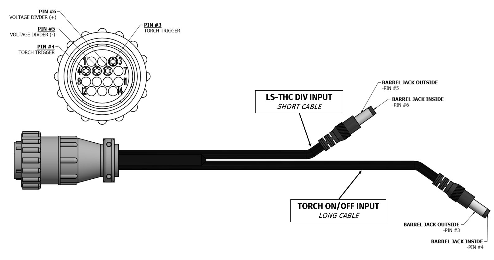
Each Razorweld CUT45 plasma cutter purchased through Langmuir Systems for use with the CrossFire PRO features a 2-pin 50:1 voltage divider port. This plasma cutter is completely plug-n-play with the Langmuir Systems CNC electronics enclosure/THC module and does not require any additional wiring. Two CNC cables are also provided in the plasma cutter box; a torch ON/OFF cable and a THC port wiring cable. Older versions of the Razorweld 45 CNC have a 4-pin Torch firing port and a 2-pin voltage divider port. You will have received the appropriate connectors in the box.
Razorweld CNC Ports
Please reference the slip included in your Razorweld Plasma Cutter Box with the included cabling to determine the orientation of your ports. We have received reports that the Torch Fire and Voltage Divider ports have been switched in a small number of Razorweld Plasma cutters.
If you are experiencing issues with your Torch not firing and your THC voltages not functioning as expected, test to see if the torch turns on and off (via Manual Torch Fire in FireControl) while plugged into the left port. Then test the right port for THC Voltage accuracy with FireControl. If you have any questions, please reach out to Langmuir Systems Support.

CUT45 THC Input Cable
For connecting the Razorweld 45 plasma cutter to the VIM box, connect the barrel jack end of the CUT45 THC INPUT CABLE into the DIV INPUT socket on the side of the VIM box. Next, connect the barrel jack end of the OUTPUT VOLTAGE CABLE to the DIV OUTPUT socket on the opposite side of the VIM box. See the image below for wiring schematic.

VIM Wiring Diagram for Razorweld CUT45
2: Hypertherm 45/65/85 with CPC Port & Machine Torch
Plug 'n Play CPC Cable
Langmuir Systems now offers an easy plug 'n play Hypertherm CPC cable option for both torch firing and Arc Voltage readings for THC. Be sure that your Hypertherm plasma cutter is compatible and has both a CPC port and Machine Torch. The cable is compatible with both the CrossFire and the CrossFire PRO.
If your Hypertherm is equipped with a CPC port and machine torch, you can use the supplied divided voltage input pigtail cable to wire your port to the LS-THC VIM box using the diagram below. Be sure to connect the barrel connector of the pigtail cable to the DIV input socket on the VIM box.

Hypertherm 45/65/85 Wiring Schematic
3: Plasma Cutter with Voltage Divider Port
For connecting the CNC voltage divider port on your plasma cutter to the VIM box, connect the barrel jack end of the DIVIDED VOLTAGE INPUT PIGTAIL CABLE into the DIV INPUT socket on the side of the VIM box. Next, connect the barrel jack end of the OUTPUT VOLTAGE CABLE to the DIV OUTPUT socket on the opposite side of the VIM box. See the image below for wiring schematic.

VIM Wiring Diagram for Voltage Divider Port
4: Plasma Cutter without CNC Port (Raw Voltage)
For connecting the main plasma terminals of your cutter into the VIM box, connect the red RAW VOLTAGE sheathed banana connector into the red CLAMP socket on the top of the VIM box and the black RAW VOLTAGE sheathed banana connector into the black TORCH socket. Next, connect the barrel jack end of the OUTPUT VOLTAGE CABLE to the PV OUTPUT socket on the other side of the VIM box.
To verify that your raw voltage pigtails were connected correctly to your plasma cutter in the previous step, check to see if you have continuity between the red male banana connector and your plasma cutter ground clamp using a multimeter. There should be no continuity between the black male banana connector and red banana connector.
To further verify proper wiring, unplug banana connectors from the VIM and use a digital mulitmeter (DMM) to measure DC voltage between the banana connectors. Plug the black DMM lead into the black banana connector and the red DMM lead into the red banana plug. This voltage should be in the 90-150V range when the Plasma Cutter is cutting.
See the image below for wiring schematic.

VIM Wiring Diagram for Raw Voltage
Installing USB Drivers for THC Module
Your computer should automatically download the needed drivers for your THC module the first time that your electronics enclosure is plugged into your computer with the provided USB cable when the THC module is installed. Please allow your computer to auto-install the appropriate drivers without interruption before opening FireControl for the first time. If your THC device is not recognized in FireControl, please follow the instructions below for how to manually install the needed USB drivers for the THC module on Windows and Mac computers.
Windows
If you are running Windows 10 on our computer, then your computer will automatically install the appropriate drivers when first plugging in the unit to your computer and the THC device should auto-connect in FireControl and function as intended.
If you are using Windows 7 or 8 you will need to manually install the driver package using the instructions below.
- Unplug any USB devices connected to your Windows Computer including the CrossFire electronics enclosure.
- Navigate to our Downloads page. Select the file and download. After downloading the file, navigate to your downloads folder and unzip the file and run the installer.
- Reconnect your USB devices and the CrossFire THC unit should be recognized and auto-connected in FireControl software as intended. To verify that your device is plugged in and recognized, navigate to ‘Device Manager’ from the Windows Control Panel. Click the down arrow next to ‘Ports (COM & LPT)’ and you should see the device ‘USB-SERIAL CH340’ connected.
macOS
If your mac computer is running on macOS Mojave 10.14 or later, then your computer will already have the drivers preinstalled and the THC device should auto-connect in FireControl and function as intended. To check your operating system version, click the apple logo in the top left corner of the task bar and select About This Mac.
If you are using an older version of macOS you will need to manually install the driver package using the instructions below.
- Unplug any USB devices connected to your Mac Computer including the CrossFire electronics enclosure.
- Open the program Terminal on your Mac (this is a default loaded program on all Mac computers).
-
Next we need to unload any drivers that may have been previously installed. To do this, copy and paste the following two commands separately into the command line in Terminal and press enter after each command.
sudo kextunload /Library/Extensions/usbserial.kext
sudo kextunload /System/Library/Extensions/usb.kext - Next we need to remove the files from the directory. Copy and paste the following two commands separately into the command line in Terminal and press enter after each command.
sudo rm -rf /System/Library/Extensions/usb.kext
sudo rm -rf /Library/Extensions/usbserial.kext - Now we need to download the driver package which can be found on our website Downloads page. Select the file and download. After downloading the file, navigate to your downloads folder and double-click the CH34x_Install_V1.5.pkg file and install. You may need to restart your computer after the download is complete.
-
Next we need to install the new driver package to the directory. To do this, copy and paste the following command into the command line in Terminal and press enter after the command.
sudo kextload /Library/Extensions/usbserial.kext
- Reconnect your USB devices and the CrossFire THC unit should be recognized
and auto-connected in FireControl software as intended. To check if your
THC module is connected to your Mac as a USB device, click the apple icon
in the toolbar and then About this Mac. Then select System Report and select
USB in the hardware drop-down menu on the left. Scroll down until you find
USB2.0 Hub and verify that a device with Product ID 0x7523 is properly shown
below this hub (this device 0x7523 is the LS-THC module). See the below
screenshot for what to expect.
![]()
- If after performing the above driver update you are still unable to connect to the THC unit, you may need to update your macOS to at least Mojave 10.14 or higher.

Getting Started with THC in FireControl
FireControl software was designed in conjunction with the Langmuir Systems THC module and USB motion control board to offer an integrated THC experience. All settings for the THC module and real-time data feedback can be accessed from the THC Control Panel in FireControl software. The manual below serves as a user guide for operating the THC module within FireControl software as well as explaining the THC settings and how they affect cutting performance. If you have not yet downloaded FireControl software, please consult the FireControl User Guide first for installation instructions.
In order to cut a program in FireControl using THC control, you will need to generate your program using a Langmuir Systems approved post processor for your CAM software (visit our Downloads page for access to our Fusion 360 and SheetCAM post processors for FireControl). A program generated without the use of our post processor will lack the necessary THC activation codes and THC will not be enabled.
Connecting to THC in FireControl
Auto-Connect
The THC Module was designed to auto-connect to FireControl when plugged into your computer. The THC module should show as the connected device ‘LS-THC’ in the upper right hand corner of FireControl as shown in the image below.

Manual-Connect
If your THC module is installed in your Langmuir Systems Motion Control Board but does not auto-connect, you may need to manually connect the device. Next to Height Control, click the ‘Connect’ button to drop down a list of available THC connections and select the LS-THC from this menu. If connected properly, the field should turn green like the previous auto-connect image. Note: refer to the previous section ‘Installing the THC Module’ to make sure that you have correctly installed your THC board into the USB Motion Control Board.

Connection Troubleshooting
If you are unable to connect your THC device via auto-connect or manual connect, it is possible that your USB drivers for the THC device are not installed properly. Please refer to the previous section ‘Installing USB Drivers for THC Module’ to verify that your drivers were installed properly and that your device is registering as a connected USB device. Also refer to section ‘Installing the THC Module’ to verify that your THC unit is correctly installed into the Motion Control Board and that the LEDs are properly illuminating on both boards.
THC Control Panel
The THC Control Panel is located on the left side of FireControl and contains all the settings and real-time data display for the THC module.
Note: the THC ControlPanel will only display when a connection to a LS-THC module is made.

The below figure highlights the features that are contained within the THC panel. Please refer to the subsequent sections for an explanation of these features and settings.

Live Voltage Display
The Live Voltage Display shows the real-time arc voltage of your plasma cutter during operation when it is connected to the CNC electronics enclosure. The voltage measuring range for the THC module is 0 - 300V.
Nominal/SMART Voltage Display
The Nominal/SMART Voltage Display shows either the programmed nominal voltage or the SMART voltage (if enabled) when cutting. If the Nominal Voltage is set to ‘0’ in the THC settings menu, then SMART voltage is enabled ( note: smart voltage is enabled in FireControl by default). The SMART voltage feature in FireControl was designed to take the guesswork out of cutting with a THC system by automatically sensing the arc voltage at the height set by the Initial Height Sensing (IHS) system and using this voltage as the nominal voltage for that cut loop. If you would prefer to manually enter a Nominal Voltage instead of using SMART voltage, you can do this in the THC settings menu.
SMART Voltage
To enable smart voltage, enter the THC settings menu and set the Nominal Voltage to ‘0’ and save. The THC panel should now display ‘SMARTV’ for Nominal Voltage to reflect that smart voltage is enabled as shown in the screenshot below.

SMART voltage works by reading the arc voltage at the start of each cut loop and automatically setting the nominal voltage to this value for the remainder of the cut loop. Since we know that the IHS system sets the torch to the ideal height at the start of each cut loop, we can measure this ideal voltage and the THC system will work to maintain this voltage during cutting.
Note: SMART voltage resets at the end of each cut and re-calculates at the start of each new cut loop.
The SMART Voltage display box will show ‘SMARTV’ until a SMART voltage is set by the THC system. Once a SMART voltage is set, it will be displayed in the Nominal Voltage box along with a ‘SMART’ logo next to the box to indicate that this was set by the SMART voltage system. Below is a screenshot of the THC panel when SMART voltage is enabled during a cut.

SMART voltage was designed so that THC operation can be easy-to-use without having to constantly change settings for optimal cutting performance. The only SMART voltage settings that you may choose to adjust are ‘Offset’ and ‘Distance’. These can be changed from the SMART Voltage sub-menu from the THC settings menu (see the settings section below for an explanation of these settings).
Nominal Voltage
The Nominal Voltage can be set manually in the THC settings menu. The Nominal Voltage is the target plasma arc voltage value that the THC system will work to maintain during cutting. Remember that the THC system works by automatically adjusting the torch height (z-axis) in order to keep a fixed arc voltage (the Nominal Voltage) throughout the cut. The Nominal Voltage can be set anywhere between 1 - 300V.
NOTE: THE MAXIMUM INPUT VOLTAGE FOR THE VIM MODULE IS 300V. DO NOT EXCEED THIS INPUT VOLTAGE! IF YOU ARE UNSURE ABOUT THE VOLTAGE OUTPUT OF YOUR PLASMA CUTTER DURING CUTTING, CONTACT YOUR PLASMA CUTTER MANUFACTURER FOR COMPLETE SPECIFICATIONS.
Choosing a Nominal Voltage for each cut will depend on many factors such as your plasma cutter, material thickness, cutting amps, material type, and the cutting feed rate. While many plasma cutter manufactures will include a table for cutting voltages based on material type and thickness, these values are more of an idealized condition and should not always be used absolutely. The best way to determine your Nominal Voltage is to perform a line test and monitor the Live cutting voltage in FireControl. We recommend cutting an 8-10” line at the desired cut speed and amperage for a given material and then entering this voltage value as the Nominal Voltage before cutting your part. To do this, jog your torch down to the material until you are at the ideal cut height. Next, turn off your electronics box and unplug the Z-axis motor from the electronics enclosure and run the line test while monitoring the Live voltage (note: your line test cannot include an IHS loop or FireControl will throw an alarm). The below image shows how FireControl should look when a Nominal Voltage of 120V is entered.

Voltage Tolerance Display
This box displays the Voltage Tolerance value that was set in the THC settings menu. The voltage tolerance value is used to establish the range of voltage values that define an acceptable arc voltage during cutting. If your live voltage value falls outside this tolerance range, the THC system will work to bring the voltage reading back to within this acceptable range by moving the Z-axis accordingly. For example, if your target voltage value is 120V and your tolerance value is set to +/-1.5V, then the THC system will not make corrective moves if the voltage value is between 118.5V to 121.5V.
THC Real-time Status Display
This display panel shows the current status of the THC system during cutting. When the THC system is activated and taking control of the Z-axis, the below LEDs indicate the current state of the THC system.
- ACTIVE - The THC system is activated and in control of the Z-axis.
- DOWN - The THC system is driving the Z-axis downward (Live Voltage > Nominal Voltage).
- OK - The Live Voltage is within the acceptable tolerance range and no Z-axis moves are being made.
- UP - The THC system is driving the Z-axis upward (Live Voltage < Nominal Voltage).
In the screenshot below, we can see that the THC system is ACTIVE and that the Z-axis is not moving (OK). This makes sense because the live voltage reading 115.3V is within the +/- 1.5V tolerance range of the 114.5V SMART Voltage that was set.
THC & the DRO
Note: When the THC system makes corrective up or down moves to the Z-axis torch, these moves do not show up as positional moves on the Z-axis Digital Read-Out (DRO) because the THC system is open-loop and does not monitor absolute position. In other words, if THC is making corrections you will see the LEDs light up on the Status Display and you can physically see the torch moving up and down (watch the lead screw coupler on the Z-axis) but you will not see the Z-axis position changing in the DRO.
Real-time Torch Speed Display
The Real-time Torch Speed Display shows the live torch speed in inches per minute (or mm/min if metric selected) as it moves around the table during jogging and cutting.
Program Speed Display
The Program Speed Display shows the programmed cutting speed when a cut program is loaded into FireControl. When a program is not loaded, the Program Speed will read N/A.
Torch Speed CUTOFF Setting
As seen in the previous two sections, FireControl monitors the live Torch Speed and also stores the Programmed Cut Speed when a program is loaded. The reason that the program speed is important for THC is because the THC system will momentarily turn off during a cut when the live Torch Speed is less than the Torch Speed CUTOFF threshold %. This is because as the torch speed momentarily decreases, such as around a tight corner or a small circle, the arc voltage will increase which can cause the torch to plunge towards the material as it tries to compensate for this sudden increase in voltage.
The Torch Speed CUTOFF setting was added to the Langmuir Systems THC system to prevent the torch from plunging towards the plate when the torch slows down (such as around tight corners or small holes). Simply put, if the live Torch Speed falls below a percentage of the Program Cut Speed, the THC will momentarily disable and stop making corrective Z-axis moves until the speed increases and returns to within range. For example, if the Torch Speed CUTOFF is set to 85% and the program cut speed is 100 in/min, then the THC will turn off whenever the live speed falls below 85 in/min.
The Torch Speed CUTOFF is set to 85% by default. It can be changed by clicking the + or - symbol on either side of the displayed percentage.
Note: For intricate art cutting programs that involve frequent back and forth motion of the torch, it’s possible that the torch never accelerates up to the programmed cut speed and therefore the THC will not turn on. We suggest monitoring the live cut speed and lowering the Torch Speed CUTOFF % if your torch is not getting up to your programmed speed.
THC On/Off Toggle
The THC On/Off Toggle button is located in the top right corner of the THC Control Panel. This toggle can be used to turn off THC control at any time. With the THC turned off, your CrossFire machine will function as normal with Z-axis control but with no THC adjustments during cutting.

Settings Menu
The THC Settings Menu can be accessed by clicking the corresponding button on the THC Control Panel. Once clicked, the THC Settings Menu will pop up on the screen as shown below.

THC settings can be changed in this menu and then saved by clicking the green ‘SAVE’ button in the lower right corner. The below ‘THC Settings’ section explains how these settings affect the performance of your THC system and the allowable values for these settings.
THC Settings Menu
The THC Settings Menu can be accessed by clicking the corresponding button on the THC Control Panel in the top right corner. Once clicked, the THC Settings Menu will pop up on the screen as shown below. The following guide lists all the THC settings and explains how these settings will affect the performance of your THC system. We recommend first running the machine with all THC settings configured to default before making any changes.
Nominal Voltage
Use this setting to adjust the Nominal Voltage for the THC system when cutting in manual mode. To enable SMART Voltage control, set the Nominal voltage to 0V. For more information on using Nominal and SMART Voltage, please see the previous section in the manual titled ‘Nominal/SMART Voltage Display’.
The Nominal Voltage can be set anywhere between 1 - 300V. The default setting is 0V for SMART Voltage.
Voltage Tolerance
The voltage tolerance value is used to establish the range of voltage values that define an acceptable arc voltage during cutting. If your live voltage value falls outside this tolerance range, the THC system will work to bring the voltage reading back to within this acceptable range by moving the Z-axis accordingly. For example, if your target voltage value is 120V and your tolerance value is set to +/-1.5V, then the THC system will not make corrective moves if the voltage value is between 118.5V to 121.5V.
The Voltage Tolerance can be set to any value between 0.1 - 10V. The default setting is 1.5V.
Voltage Sample Size
The Voltage Sample Size is used to control the how course or fine your real-time voltage readings are tuned. A value of 50 in Voltage Sample Size indicates that 50 successive voltage readings are taken and averaged by the THC module before posting a voltage value (this happens in a fraction of a second). While a larger Voltage Sample Size value will result in a smoother voltage reading, it will also take longer to sample and your system may be slow to react to large changes in plate height. We recommend operating the THC system at the default 50 for Voltage Sample Size. If you are running a lower quality plasma cutter, your arc voltage might be more erratic which can result in inconsistent THC movements. We suggest slowly increasing the Voltage Sample Size in the THC settings menu until a smoother live voltage reading is achieved.
The Voltage Sample Size can be set to any value between 10 - 300. The default setting is 50.
SMART Voltage Offset
As explained in the above ‘Nominal/SMART Voltage’ section, SMART Voltage works by automatically setting a Nominal Voltage by measuring and averaging the voltage after the height is set by the IHS system at the start of each cut loop. The SMART Voltage Offset Setting is the distance (in inches) after a cut is started that is ignored by the SMART Voltage averaging algorithm. By ignoring the first part of a cut, this allows the plasma cutter to settle into a more stable voltage after a successful pierce before measuring and averaging voltages for SMART Voltage. The below diagram represents the sequence of events that happens at the start of each cut for setting the SMART Voltage.
The SMART Voltage Offset can be set anywhere between 0.01 to 1 inch. The default setting is 0.25 inches.

SMART Voltage Distance
The SMART Voltage Distance is the total distance traveled after the Smart Offset distance during which the live voltage readings are measured and averaged by the THC module. This average voltage becomes the SMART Voltage and it is calculated at the start of each cut. The combined total distance between Smart Offset and Smart Distance is also helpful for preventing the THC unit from turning on and taking control on small holes and features which can be prone to torch diving. For example, with the default of 0.25 inches for both Smart Offset and Smart Distance, THC will only turn on with Smart Voltage when a cut loop has a total length that exceeds 0.5 inches.
The SMART Voltage Distance can be set anywhere between 0.01 to 10 inches. The default setting is 0.25 inches.
Torch Speed CUTOFF
See previous section titled ‘Torch Speed CUTOFF Setting’ for an explanation of this setting. This setting can be changed from the THC Control Panel or the THC Settings Menu.
The Torch Speed CUTOFF can be set anywhere between 1 to 100%. The default setting is 85%.
Z-Speed Factor
The Z-Speed Factor setting is used to tune the Z-axis travel speed when the THC module is in control. The Z-Speed Factor is used to set the real-time Z-axis travel speed as a percentage of the real-time XY travel speed. This makes it so that the Z-axis motor can move faster when the XY speed is faster, but also slow down when the XY speed gets slower such as around tight corners or small holes. This feature allows the torch to react to sudden changes in plate height when moving quickly, but also prevents the torch from plunging downward when the torch speed slows down. The Z-Speed Factor sets the Z-axis speed based on a percentage of the current XY speed. For example, if the Z-Speed Factor is set to 10% and the live XY speed at some point during a cut is 100 IPM, then the Z-axis speed at that point in time would be 10% of 100 IPM or 10 IPM. If your plate is especially warped, you may need to increase the Z-Speed Factor so that the Z-axis motor can move quickly enough to keep up with large changes in plate height. For most cutting needs, the default setting of 5% will be sufficient. For example, a 5% Z-Speed Factor can correct up to 4" out of flat over 48".
The max Z-Axis travel speed under THC control is 60IPM; if the calculated speed exceeds 60IPM then 60IPM will be used.
The Z-Speed Factor can be set anywhere between 1 to 99%. The default setting is 5%.
Restore Default Settings
The ‘Restore Default’ settings button in the THC Settings Menu can be used to restore the THC settings back to the factory default settings.

Troubleshooting your THC System
THC TROUBLESHOOTING GUIDE
Due to the complex nature of the Torch Height Control system, we have compiled
a flow chart of the common LS-THC issues, identification steps, and remedies.
LS-THC Troubleshooting Flow Chart →
Live Voltage Readings not Updating
- Check that your THC unit is connected in FireControl. To verify that your THC unit is connected and responding, jog the machine around in X and Y and make sure that the live ‘Torch Speed’ is updating properly.
- Reset your LS-THC connection in FireControl or restart FireControl software.
- Verify that your plasma cutter is properly connected to the VIM box and that your THC Output Cable (connecting the VIM box to the electronics enclosure) is connected to the appropriate port. Refer to the above section ‘VIM Box Wiring Schematics’ to make sure that everything is wired correctly. The THC unit will read 0V if your work clamp and torch lead polarities are crossed; please make sure that you are following the guide correctly when wiring for raw plasma terminals or a 50:1 CNC Port.
THC not Turning on During Cut Program
- If your live ‘Torch Speed’ never gets above the Torch Speed CUTOFF %, then your THC will not turn on. This can happen with tight and complex artwork where the torch doesn’t have enough straight-line distance to accelerate up to the programmed cutting speed. You can either edit your program to lower the cutting speed or you can lower the Torch Speed CUTOFF % in the THC Control Panel so that THC turns on at a slower speed.
- Check that you are getting a Live Voltage reading in the THC Control Panel. THC will not turn on if you do not have a voltage reading during cutting.
- If your THC does not turn on with SmartVoltage enabled, check your SmartVoltage Offset and Distance settings in the THC settings menu. Verify that your cutting loop is larger than the sum of these two distances or a SmartVoltage will never be set.
- THC will only make corrective Z-axis moves when the live voltage falls outside the tolerance voltage range. If your tolerance voltage is too large, THC may not turn on.
Torch ‘Bobs Up and Down’ During Cutting
If your THC settings are not properly tuned, you may notice that the torch will ‘bob up and down’ as the THC system is overhunting for the nominal voltage. Try tweaking the below settings and observe if the situation improves.
- Increase Voltage Sample Size
- Increase Voltage Tolerance Range
- Lower the Z-Speed Factor
Live Torch Speed not Showing in FireControl
If your Live Torch speed is not updating in FireControl with your THC module connected, then there could be a timeout issue. We suggest manually disconnecting the USB cable from your electronics box and restarting FireControl before plugging the cable back in.
Torch Plunges Down into Material
When the plasma torch slows down in speed, such as around tight corners or arcs, this causes the voltage to instantaneously increase and the THC module will move the torch downward to compensate. FireControl and LS-THC have several features and settings that help to prevent the torch from plunging down into the material during normal operation. If you are still experiencing this issue, the below steps can help to prevent this issue from occurring.
- Increase your Torch Speed CUTOFF %
- Lower the Z-Speed Factor
LS-THC not Connecting in FireControl
- Verify that your THC module is properly installed into the USB Motion Control Board (see section ‘Installing the THC Module’ above).
- Verify that your USB drivers are properly installed for the THC unit (see section ‘Installing USB Drivers for THC Module’ above).
- Unplug the USB cable from your computer and restart FireControl. Re-plug the USB cable back into your computer.
Live Voltage Readings are Erratic
If you are running a lower quality plasma cutter, your live arc voltage readings may be more erratic which can result in inconsistent THC movements. We suggest slowly increasing the Voltage Sample Size in the THC settings menu until a smoother live voltage reading is achieved.
Arc Voltage Lost Errors
The LS-THC system monitors arc voltage during cutting and will pause a program if the THC unit senses that the arc is lost anytime during a program. This allows the user to troubleshoot any issues with their system before continuing to cut. FireControl will also prompt the user to execute an optional ‘Run From Here’ move in order to pick up the cut at the same loop that the pause happened after troubleshooting the issue.
Below is a list of common causes for why you may have lost arc voltage on your system both during a pierce event and during cutting.
During Pierce
- Pierce delay is too long: If your plasma cutter starts the arc properly but stays in the same position too long it can lose the arc once the pierce hole becomes too large. This is most common on thin gauge metal.
- Pierce delay is too short: If your plasma cutter has a small delay between when the torch trigger is pulled and when the pilot arc starts, it is possible that this small delay is shorter than your programmed pierce delay. In this instance, the THC unit will think that the arc was lost and pause the program. We recommend increasing your pierce delay to get the torch to arc and pierce properly before motion begins.
- Pierce height too high: If your pierce height is too high, the pilot arc may initiate but never transfer to the plate which can cause the torch to extinguish the pilot arc after a short duration. We recommend using a pierce height around 0.15”.
- Plasma cutter hooked up incorrectly to VIM box: Please follow our THC guide for how to correctly attach your cutter to the VIM module for measuring voltage. If the polarity of the wiring is reversed incorrectly, a voltage will not display in FireControl. A good test to see if your plasma cutter is attached correctly is to manually fire the plasma cutter pilot arc by hand in the air and making sure that a voltage displays briefly in FireControl.
- Plasma cutter misfire: If your plasma cutter misfires while attempting to fire the pilot arc, then open circuit voltage will be detected by the VIM module and the program will pause. Some causes of plasma cutter misfires include worn out electrodes, retaining caps that are too tight, and debris in the spring mechanism of the electrode. If misfires occur frequently we suggest disassembling your torch head, replacing the consumables, and cycling the electrode spring back and forth and making sure that everything moves freely.
During Cutting
- Tool path intersects or is too close to a previously cut toolpath: If you have a tight program such as artwork it is possible that you are getting too close to a previously cut toolpath and the plasma cutter can lose arc while cutting, especially on thinner material. This can also happen when your programmed tool path runs over a hole in your material.
- Lead-in/Lead-out Issue: If your lead-in and lead-out geometry is self intersecting, the arc may be lost while making the lead-out. We suggest altering your geometry to remedy this issue.