Vulcan16 Assembly Guide
Safety
When used correctly, the Langmuir Systems Vulcan16 will offer you years of safe operation. However, like all other automated and industrial type machinery, there are important safety considerations and precautions that must be followed in order to avoid injury. Study these safety warnings carefully before assembling and using your machine.

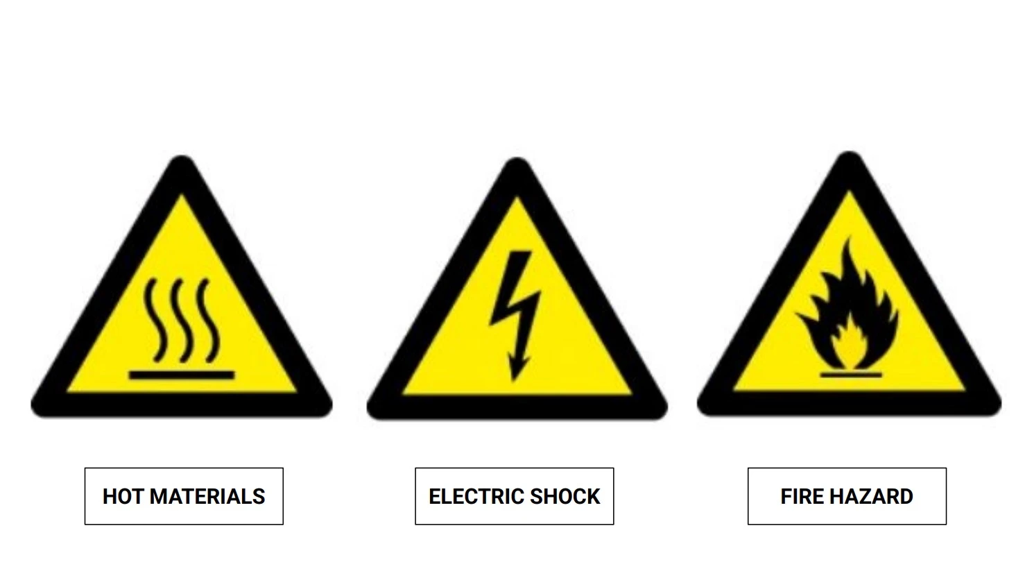
ELECTRIC SHOCK
Electric shock can cause serious injury or death. This machine requires the use of high voltage electricity to operate. To avoid injury, always adhere to the following precautions:
- Never touch bare wires/buses/connections or components that are carrying electricity.
- Repair or replace all worn or damaged components. Turn off power to machine and plasma cutter when making repairs.
- Install and maintain equipment in accordance with the National Electric Code (NEC)
- If you have limited electrical knowledge/experience, hire a certified electrician to perform all electrical work.

FIRE AND EXPLOSION
The Vulcan 16 is not designed to contain explosions or fires. The oven is outfitted with fire retardant mineral wool insulation to mitigate potential hazards from open flames. Electrical fires can be caused if the machine is operated incorrectly. To avoid injury, always adhere to the following precautions.
- Never operate the machine in the vicinity of flammable materials or where there are volatile and combustible fumes in the air.
- Always keep a fire extinguisher nearby in case of emergency.
- Never operate the machine in a poorly ventilated area.
- Be sure to read and understand all MSDS safety data for any materials and powders used while operating the Vulcan 16.
- NEVER store flammable materials on top of or inside of the Vulcan 16

HAZARDOUS FUMES
Gases and fumes produced during the powder coating process can be hazardous to your health. To avoid injury, always adhere to the following precautions:
- Wear a properly rated respiratory mask during use of the machine. Never operate the machine in an area with minimal or no ventilation. Use fans and blowers to remove fumes and gases from the work area.
- If ventilation is poor, use an air-supplied respirator system.
- The type of fumes and hazard level depends greatly on the powder being sprayed. Before coating, consult the Material Data Safety Sheet (MSDS) for specific guidelines on the type and hazard level of the fumes produced during coating.

PINCH AND CRUSH POINTS
This machine can create pinch points during normal assembly. To avoid injury, always adhere to the following precautions:
- Do not place any part of your body in defined crush points on the machine when it is being assembled.
- Be aware of all areas of the machine that could potentially be a pinching hazard, such as nested flanges, hinge points, and add-on attachment areas.

HOT MATERIALS
The curing process uses extremely high temperatures to cure powder coat. As a result, the material will be very hot after curing which can cause burns. To avoid injury, always adhere to the following precautions:
- Always assume that metal resting on or in the machine is hot enough to cause severe burns.
- Always allow the metal to sufficiently cool before handling.
- Never handle hot metal with bare hands. Use gloves or tongs to remove material from the machine.
WARNING
This product can expose you to chemicals which are known to the State of California to cause
cancer, birth defects or other reproductive harm. For more information go to www.P65Warnings.ca.gov.
Vulcan 16 Assembly Guide
Images in this Guide
The assembly drawings and pictures included in this guide can be expanded to
full-screen and zoomed to provide more detail on a given step.
1: The Shell
The first step in the assembly process is to assemble the 5 walls that make up the unit.
Materials
Parts
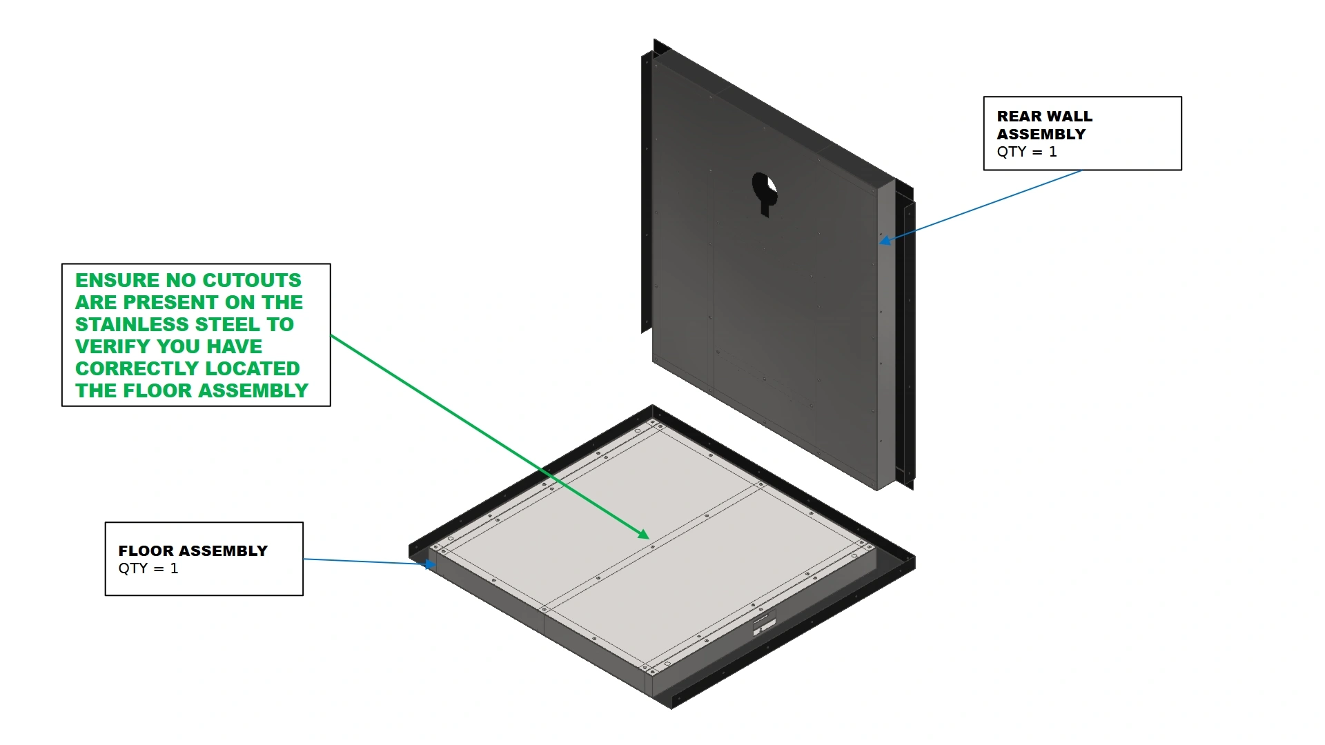
- (1) Floor Assembly
- (1) Rear Wall Assembly
Hardware
- N/A
Tools
- (Optional) Rubber Mallet
- (Optional) 2x4 / Wood block
Instructions
NOTE
The total weight of the assembled unit is above 200lbs.
Assembly-In-Place is recommended for users who did not purchase a leg kit
and do not have access to lifting equipment.
IMPORTANT
Assembly will require access to the back and top of the unit. Ensure enough space is available during assembly to safely reach all sides of the unit.

PINCH HAZARD
Never place extremities in the U-shaped channels when placing wall assemblies. Thin sheet metal flanges create a pinch point that can result in serious injury.
- Locate the Floor Assembly and place it on an even and stable surface such that the edge NOT enclosed by a sheet metal flange is closest to you as shown. The Floor assembly will not have any cutouts present in the stainless steel as a means to differentiate between the floor and ceiling assembly.
- Locate the Rear Wall Assembly.
- Place the Rear Wall Assembly into the U-Shaped channel on the back side of the floor assembly formed by the outer sheet metal in the same orientation as shown in the image above. A rubber mallet can be used to fine tune the position of your Rear Wall relative to the Floor Assembly.
Note
If using a mallet, it is recommended to use a scrap piece of wood to
distribute the force of the mallet and avoid damaging the walls. Damage as a
result of malleting is not covered in your Vulcan’s warranty
Materials
Parts
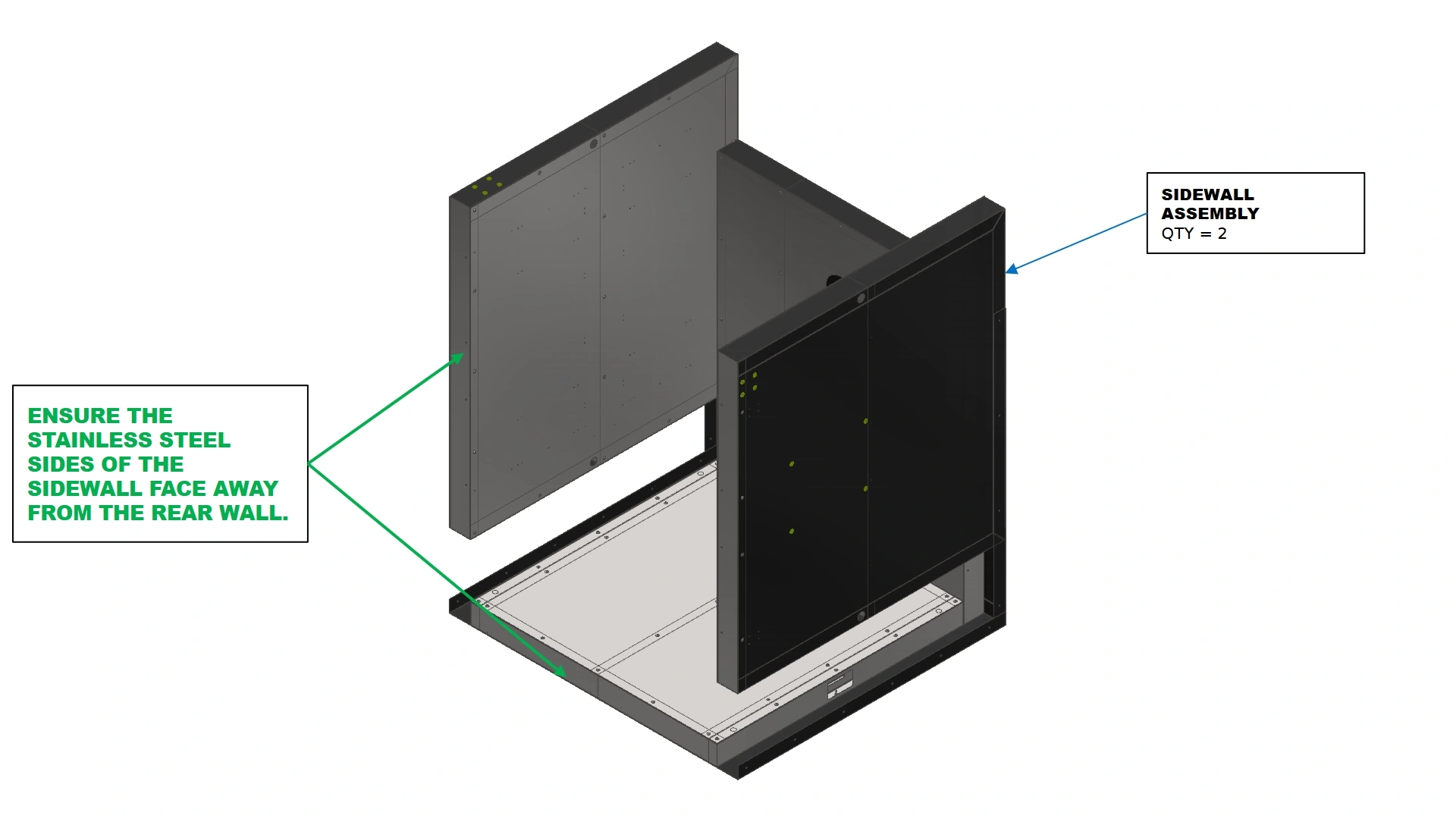
- (2) Sidewall Assembly
Hardware
- N/A
Tools
- (Optional) Rubber Mallet
- (Optional) 2x4 / Wood block
Instructions
- Locate the Sidewall Assemblies.
- In a similar fashion to the Rear wall, carefully lower the sidewall into the U-shaped channels formed by the Floor and Rear Wall Assembly’s outer skin.
- Position the Sidewall in the channels such that the stainless steel edge of the wall is flush with the edge of the floor that is not enclosed by a sheet metal flange.The outer flanges of the rear wall will wrap around the back side of the sidewall assembly.
Note
If done correctly, the left side of the unit will have exposed Rivet Nuts on the top left of the wall while the right side will be a flat, consistent surface.
Note
The fitment of the walls into the U-Shaped Channel can be tight and may require minor positional adjustments of the walls with a rubber mallet and block of wood.
Materials
Parts
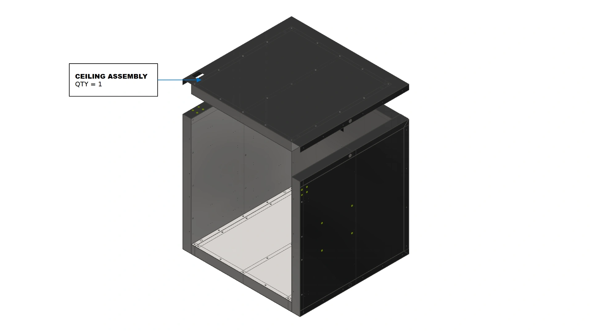
- (1) Ceiling Assembly
Hardware
- N/A
Tools
- (Optional) Rubber Mallet
- (Optional) 2x4 / Wood block
Instructions
- Locate the Ceiling Assembly.
- Position the Ceiling Assembly such that the orientation mirrors that of the floor assembly and the exposed edge is flush with the exposed edges of the sidewalls.
- Lower the Ceiling Assembly into place such that the U-Shaped channel encompasses all three walls and the exposed Rivet Nuts on the left sidewall sit within the pocket cutout located on top of the ceiling assembly as shown.
Note
A rubber mallet may be necessary to fully seat the ceiling assembly due to tight bend radii. It is recommended to provide temporary vertical support to the ceiling until it is properly secured to prevent damage to sheet metal flanges.
Materials
Parts
- N/A
Hardware
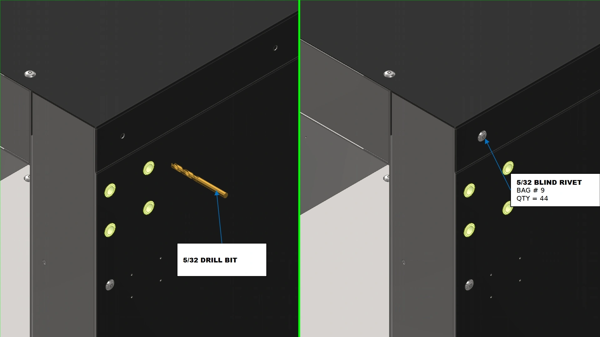
- (44) 5/32 Blind Rivet
Tools
- 5/32 Drill Bit
- Hand Drill
- Rivet Gun
- (Optional) Center Punch
Instructions
- Starting in the top right-hand corner of the Vulcan 16, use the provided pilot hole and a 5/32 drill bit to bore a hole into the sidewall’s outer sheet metal. Once you hit insulation, back the drill out.
- Using a 5/32 blind rivet and a rivet gun, rivet the flange to the sidewall assembly using the hole bored in the previous step
NoteEnsure the wall assemblies of your Vulcan 16 powder coat oven are flush and properly assembled before applying any rivets.
- Repeat steps D1 & D2 for all remaining 43 pilot hole locations identified by the wall flanges.
2. The Door
The second step in the assembly process is to prepare the door assembly.
Materials
Parts
- (1) Door Assembly
- (1) Top Door Hinge Assembly
- (1) Bottom Door Hinge Assembly
Hardware
- N/A
Tools
- N/A
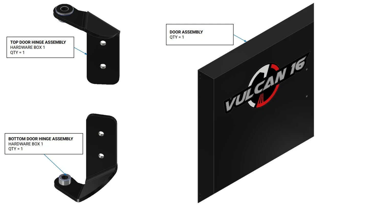
Instructions
- Locate the Door Assembly that came with your unit.
- Locate the Top Door Hinge Assembly & Bottom Door Hinge Assembly located in Hardware Box 1
Materials
Parts
- (1) Door Assembly
- (1) Top Door Hinge Assembly
- (1) Bottom Door Hinge Assembly
Hardware
- (4) 4.8mm Blind Rivets
Tools
- Rivet Gun
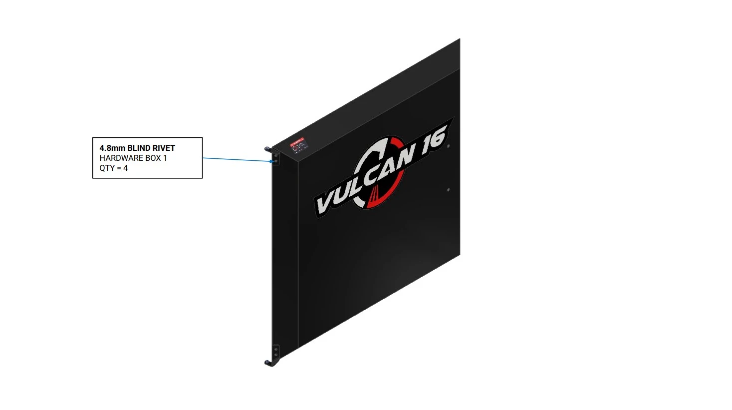
Instructions
- Using the provided Rivets located in Hardware Box 1, install the bottom and top door hinge assembly onto the door using the provided holes.
Materials
Parts
- (1) Door Assembly
- (1) Door Handle
Hardware
- (2) M8 X 56mm SPACER
- (2) M8 X 1.25 X 80mm SHCS
- (2) M8 X 1.25 FLANGE NUT
Tools
- 6mm Hex Key
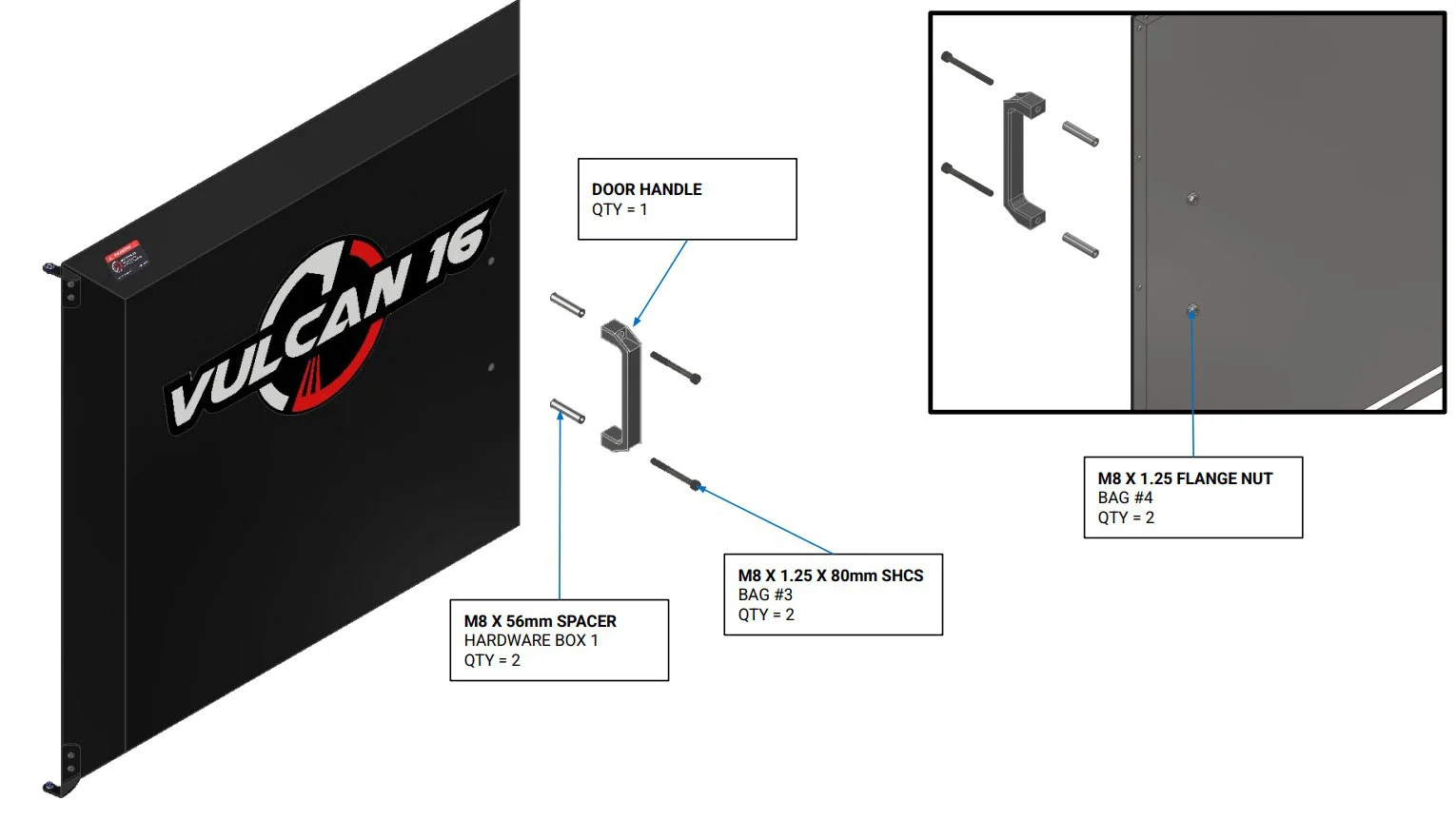
Instructions
- Locate the Door Handle.
- Using a rod, screwdriver or similar tool, create a gap in the insulation blocking the handle mounting hole locations to allow the M8 x 56mm Spacers to pass through.
- Using the fasteners shown, Install the Door Handle on the door using the designated cutouts using a 6mm Hex Key.
Materials
Parts
- (1) Door Assembly
Hardware
- (1) Woven Gasket with Clips
Tools
- Drill
- 5/32nd drill bit for stainless steel
- Safety glasses
- Gloves
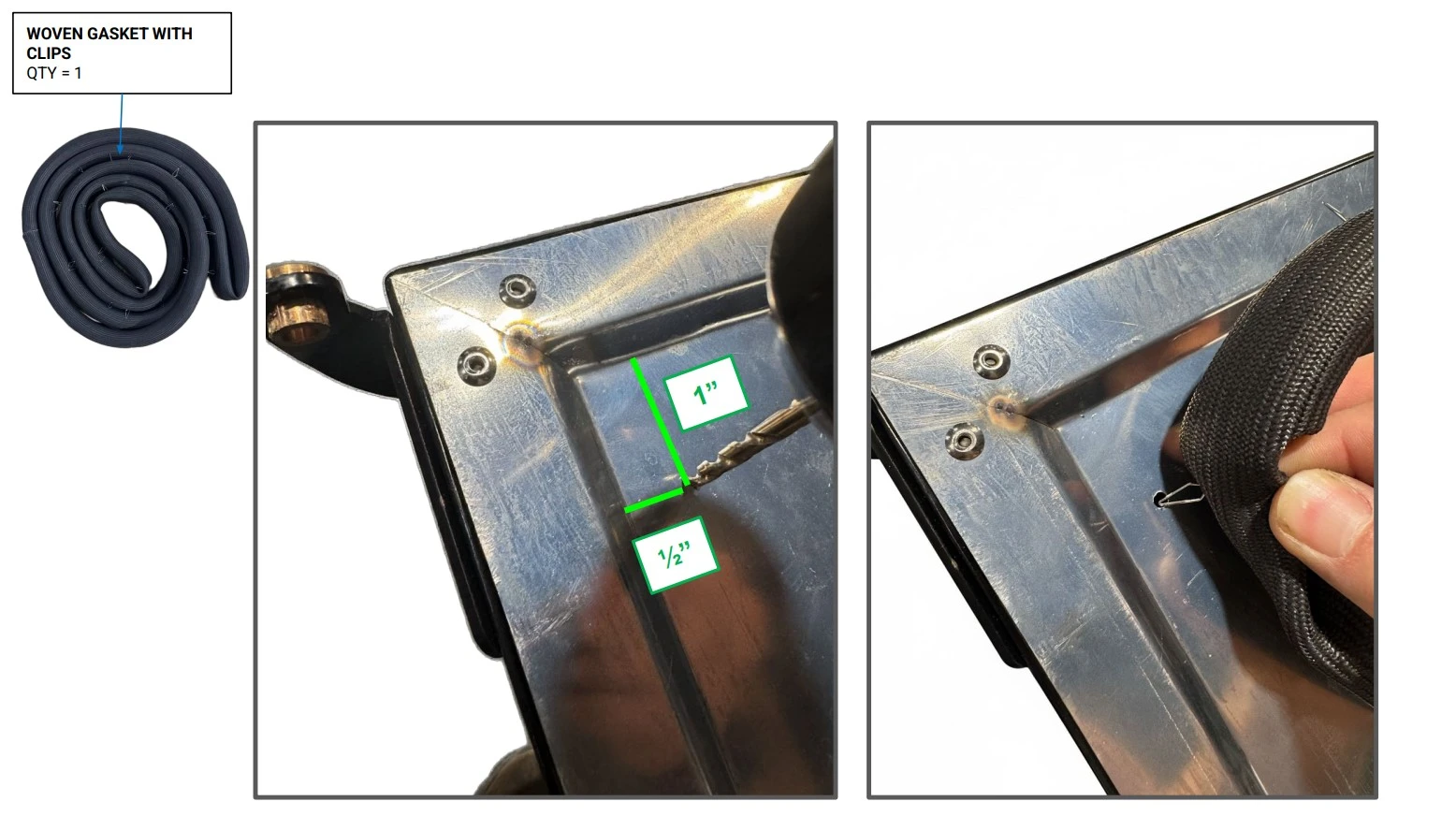
Instructions
WARNING
Drilling into sheet metal will produce sharp metal chips and burrs. It is recommended to wear proper PPE during this step.
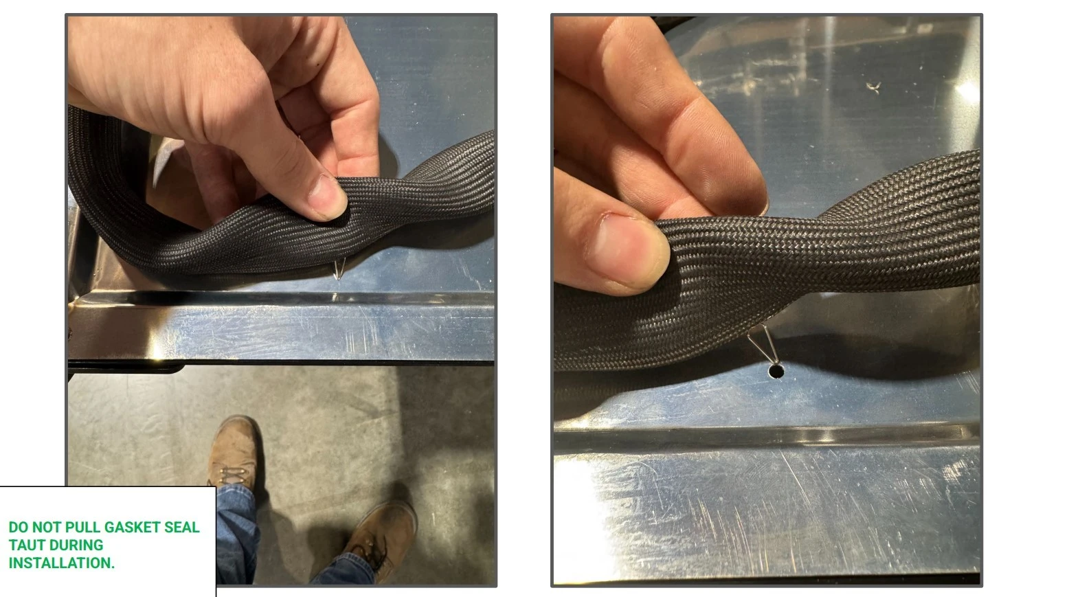
- Locate the Woven Gasket with Clips and a drill with a 5/32nd bit.
- Starting in the corner adjacent to the top hinge bracket, drill a hole approximately 1 inch down from the ridge parallel to the top edge of the door and ½ an inch from the ridge parallel to the hinge side of the door as shown.
- Insert one of the clips of the gasket into the hole.
Materials
Parts
- (1) Door Assembly
Hardware
- (1) Woven Gasket with Clips
Tools
- Drill
- 5/32nd drill bit for stainless steel
- Safety glasses
- Gloves
Instructions
- Without pulling the seal taut, move the next clip into position below the previously drilled hole approximately 4 inches away.
- Drill the next hole and place the clip into the hole.
- Repeat steps E1 and E2 for all clips in the door seal.
Materials
Parts
- (1) Door Assembly
Hardware
- (1) Woven Gasket with Clips
Tools
- Drill
- 5/32nd drill bit for stainless steel
- Safety glasses
- Gloves
Instructions
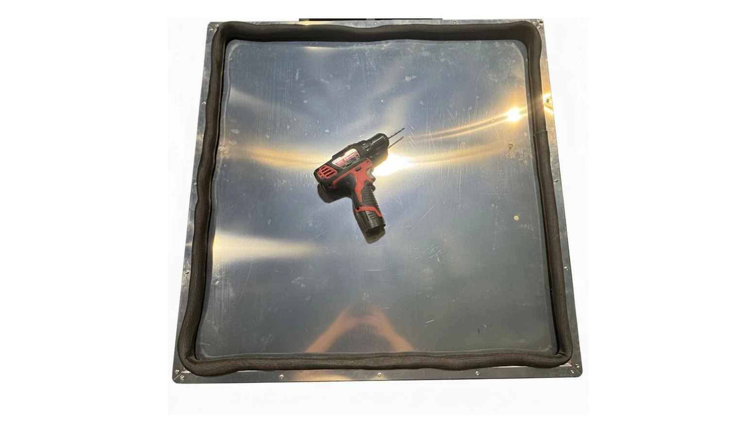
- Ensure the fully installed door seal is not stretched at any point in the loop and that there is a slight buildup of seal in the corners to assist with proper seating. See image for reference
3. Mounting the Door
The third step in the assembly process is to mount the door to the unit.
Materials
Parts
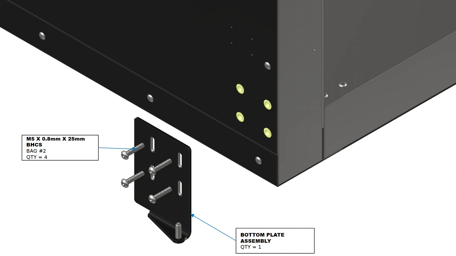
- (1) Bottom Plate Assembly
Hardware
- (4) M5 x 0.8mm x 25mm BHCS
Tools
- 3mm Hex Key
Instructions
- Locate the Bottom Plate Assembly and position the plate such that the 6mm Captive Pin points upwards.
- Install the Bottom Plate Assembly using the fasteners shown. Do not fully tighten the fasteners at this point.
Materials
Parts
- (1) Door Assembly
Hardware
- N/A
Tools
- 3mm Hex Key
- (Optional) Vertical Prop
Instructions
- Locate the completed Door Assembly.
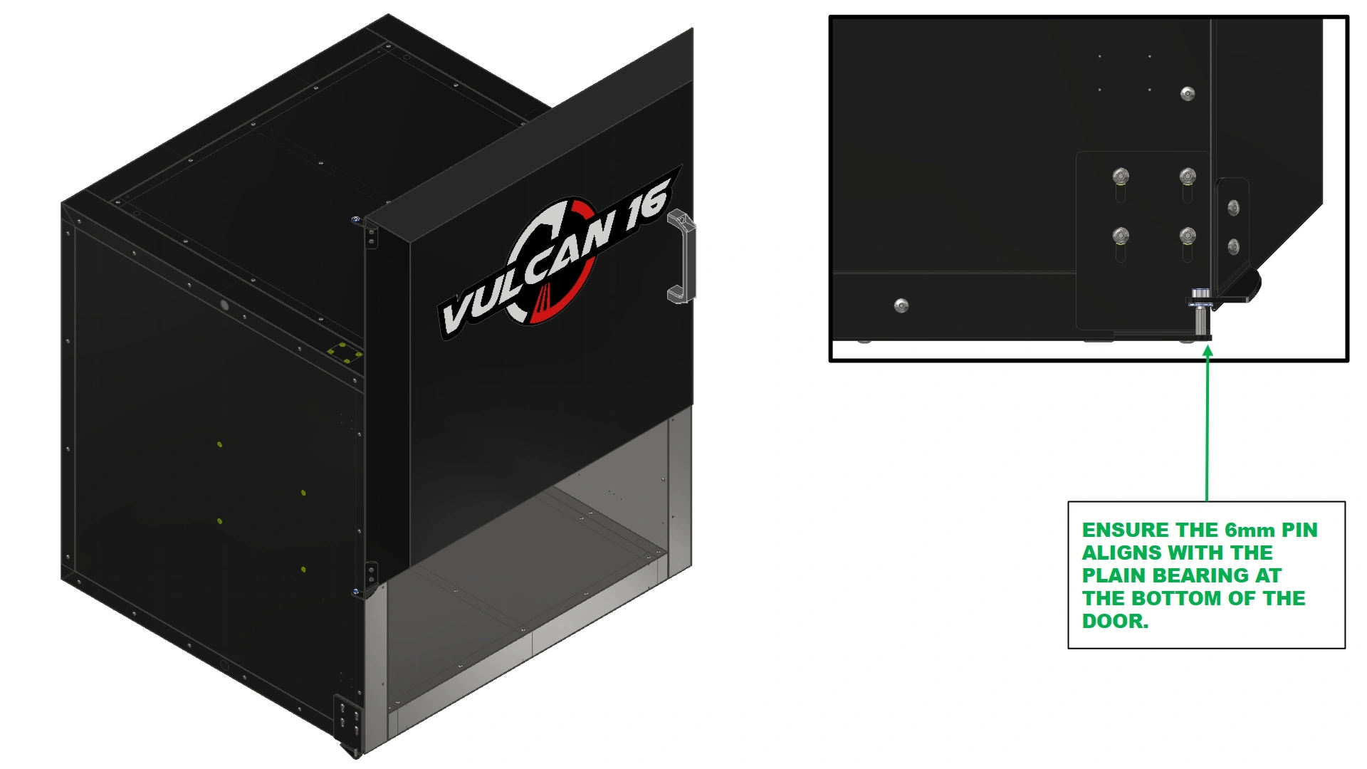
- Position the door such that the outer perimeter of the door assembly is flush with the outer perimeter of the Vulcan’s body. Slide the door down onto the 6mm captive pin in order to create the hinge point of the door.
NoteTo create a good thermal seal, the adhesive backed seal will protrude ¼” from the door for compression. If needed, you may adjust the doors position to avoid interference with the seal during mounting.
- Ensure the Door Assembly is seated such that the 6mm pin is fully seated in the door’s bottom Plain Bearing.
NoteTo prevent any damage to the hinge plates, be prepared to temporarily support the door’s weight with a vertical prop if necessary.
Materials
Parts
- (1) Top Plate Assembly
Hardware
- (4) M5 x 0.8mm x 25mm BHCS
Tools
- 3mm Hex Key
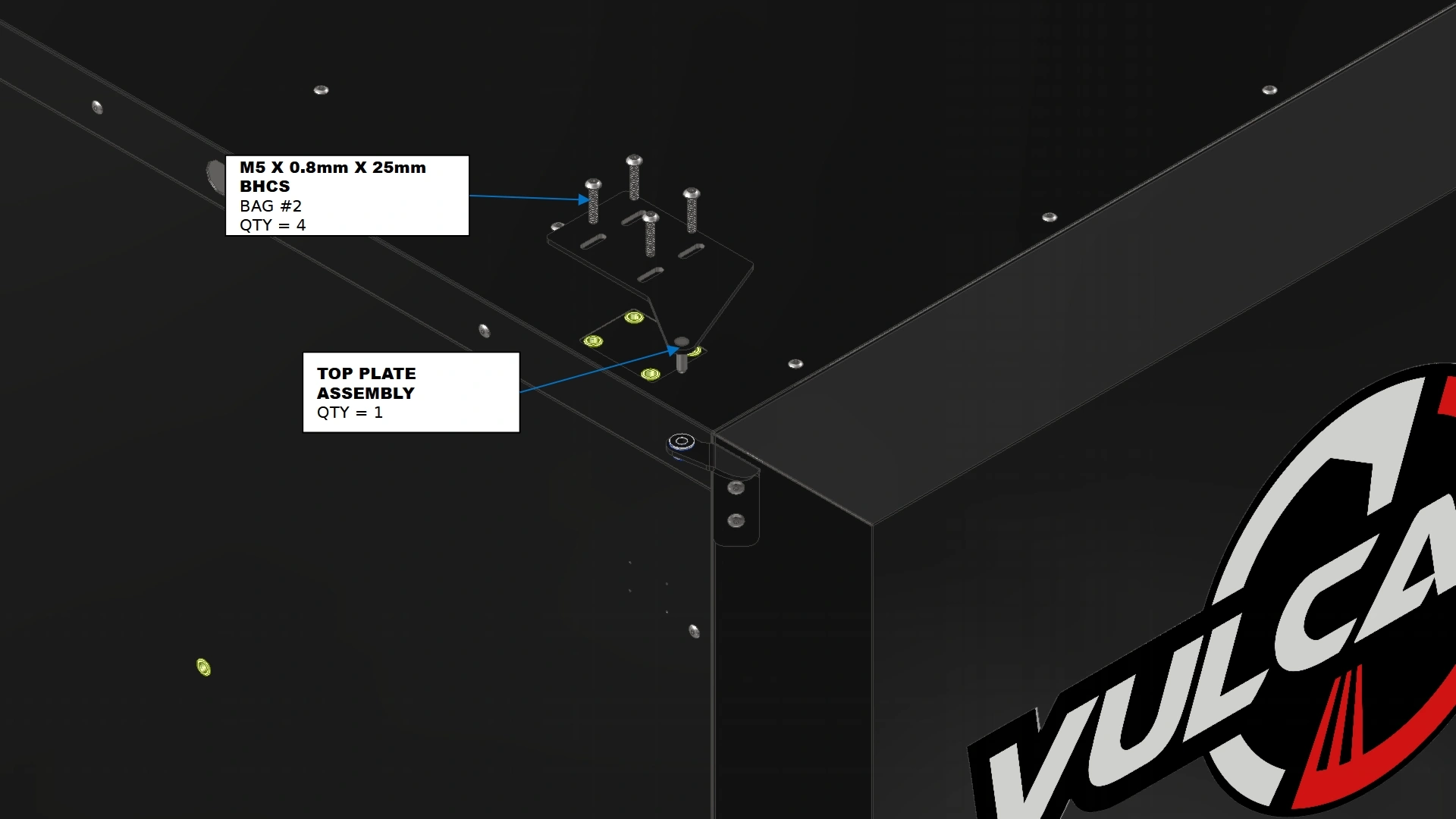
Instructions
- Locate the Top Plate Assembly and position it such that the 6mm captive pin is directed down towards the ground as shown.
- Align the exposed 6mm captive pin with the plain bearing at the top of the door and insert the pin.
- Install the Top Plate Assembly using the fasteners shown.
- If the door to your oven is square to the frame, you can skip step 4 and continue to Step 5.
4. Door Adjustments
The fourth step in the assembly process is to adjust door fitment to ensure proper alignment and seal.
Materials
Parts
- N/A
Hardware
- N/A
Tools
- 3mm Hex Key
Instructions
- Once the door is installed, take a step back and determine if there is any noticeable sag on the upper right corner of the unit or if there is a noticeable offset in the door to one side of the oven.
- The door should be straight on with the frame. If the door is square, you may skip this step and proceed with assembly.
- If your door has noticeable sag or offset, follow the adjustment instructions on the following pages.
Materials
Parts
- N/A
Hardware
- N/A
Tools
- 3mm Hex Key
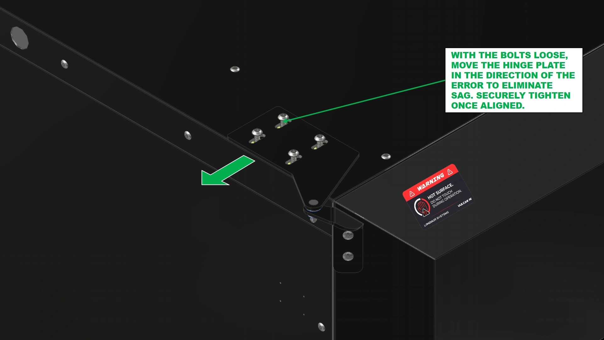
Instructions
- To address sag, use a 3mm hex key and back out the fasteners that secure the Top Hinge Plate of the door to allow free movement of the plate along the slots.
- With the fasteners loose, grab the handle of the oven door and pull the door upward to remove the visible sag. The hinge plate will naturally shift with the door’s position.
NoteA small prop may be needed to keep the door in place once sag is removed.
- When the door is square and there is no longer any visible sag, use the 3mm hex key to tighten the Top Hinge Plate into position.
Materials
Parts
- (2) M-Style Shims (optional)
Hardware
- (4) M5 x 0.8mm x 25mm BHCS
Tools
- 3mm Hex Key
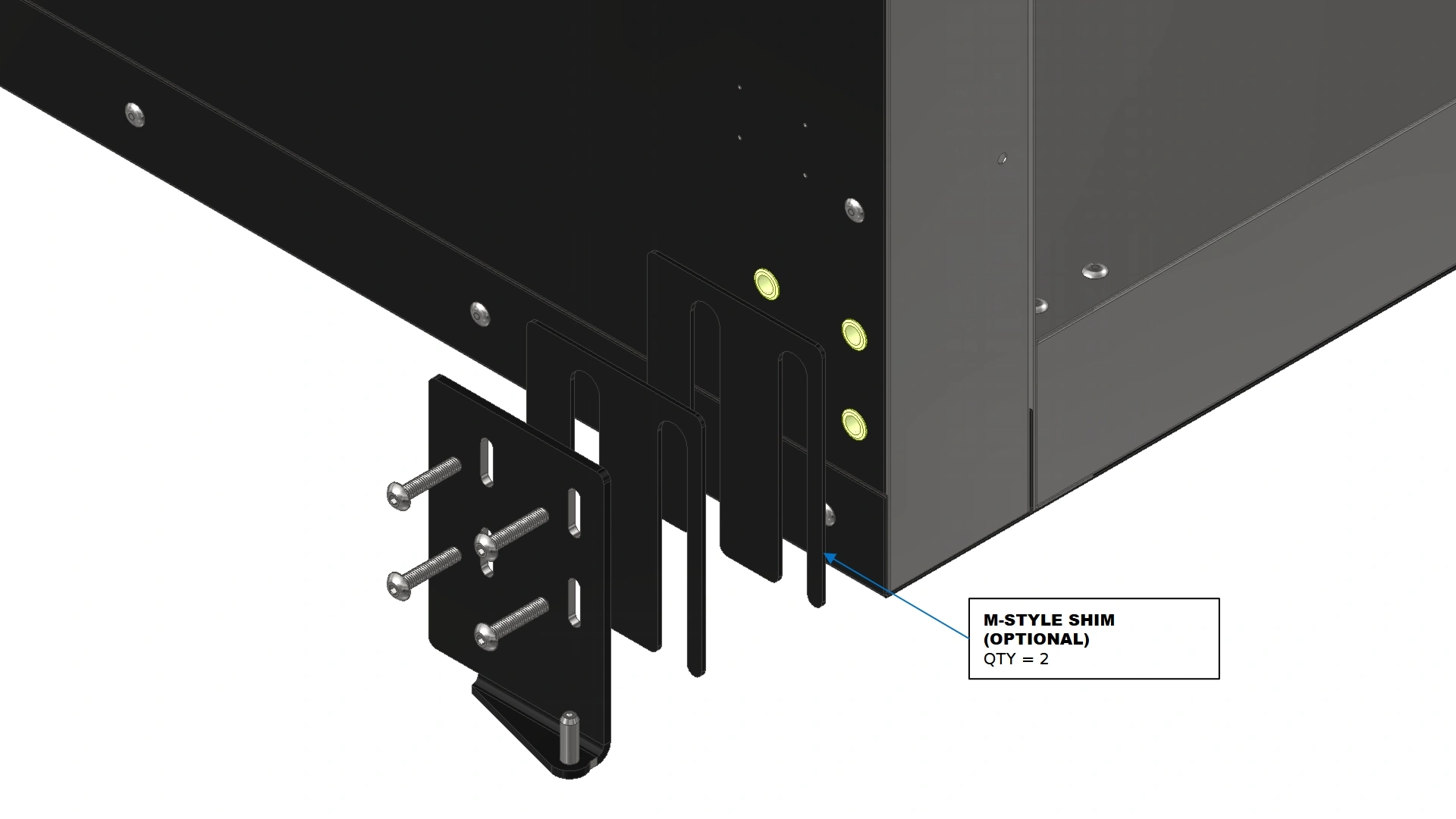
Instructions
- To address a natural offset in the door, loosen the Bottom Plate Assembly previously installed in step 3.
- Place one or both of the M-style shims behind the bottom plate assembly to combat the natural offset of the door and move the position of the door towards the hinge points.
5. Door Latches
The fifth step in the assembly process is to install the compression latches.
Materials
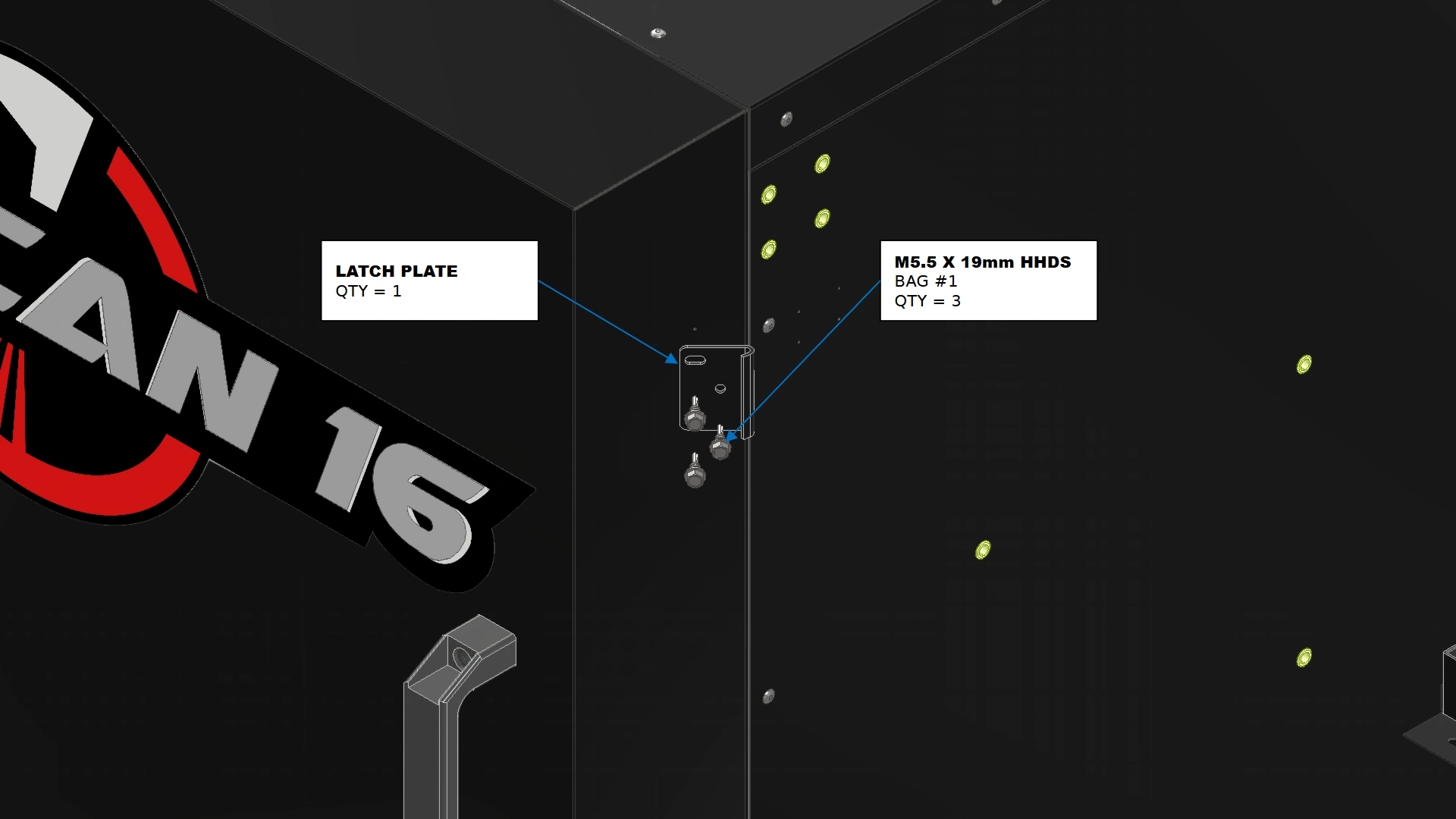
Parts
- (1) Latch Plate
Hardware
- (3) M5.5 x 19mm HHDS
Tools
- 8mm Hex Drive Socket
- Drill / Impact Driver
Instructions
- Locate the Latch Plate that came with your Vulcan 16 Hardware.
- Position the latch such that the curled edge is tangent with the edge of the door as shown.
- Secure the plate onto the door’s chamfer using the back two slotted features of the latch plate with the fasteners shown. Do not fully tighten the fasteners.
- Adjust the latch plate along the slots to ensure the bent up edge is extended slightly beyond the edge of the door.
- Using the remaining fastener and hole feature, secure the plate in place. Fully tighten the remaining fasteners.
Materials
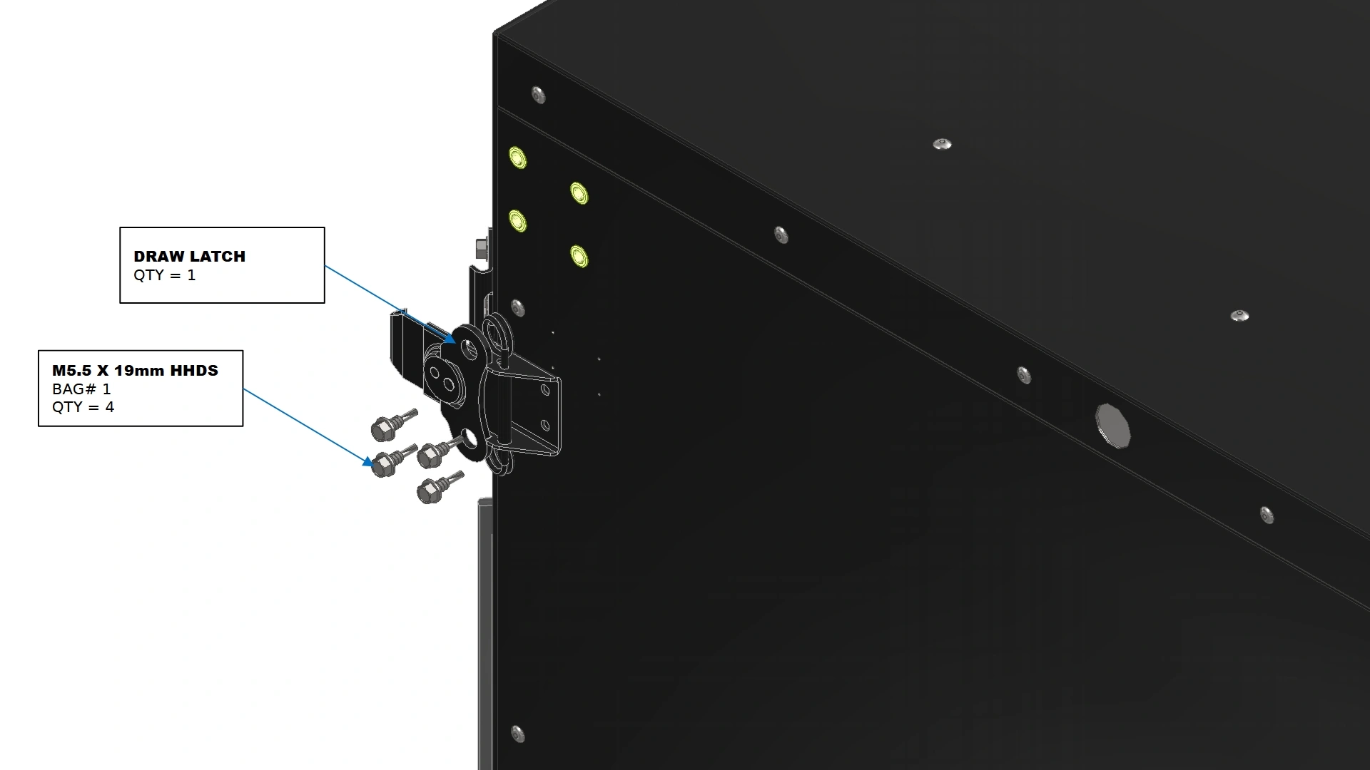
Parts
- (1) Draw latch
Hardware
- (4) M5.5 x 19mm HHDS
Tools
- 8mm Hex Drive Socket
- Drill / Impact Driver
Instructions
- Locate the Draw Latch that came with your Vulcan 16 Hardware.
- Secure the latch on the sidewall using the provided pilot holes with the fasteners shown.
- Repeat Step 5 for the remaining door latch on the bottom of the oven.
6. The Door Switch
The sixth step in the assembly process is to install the door switch.
Materials
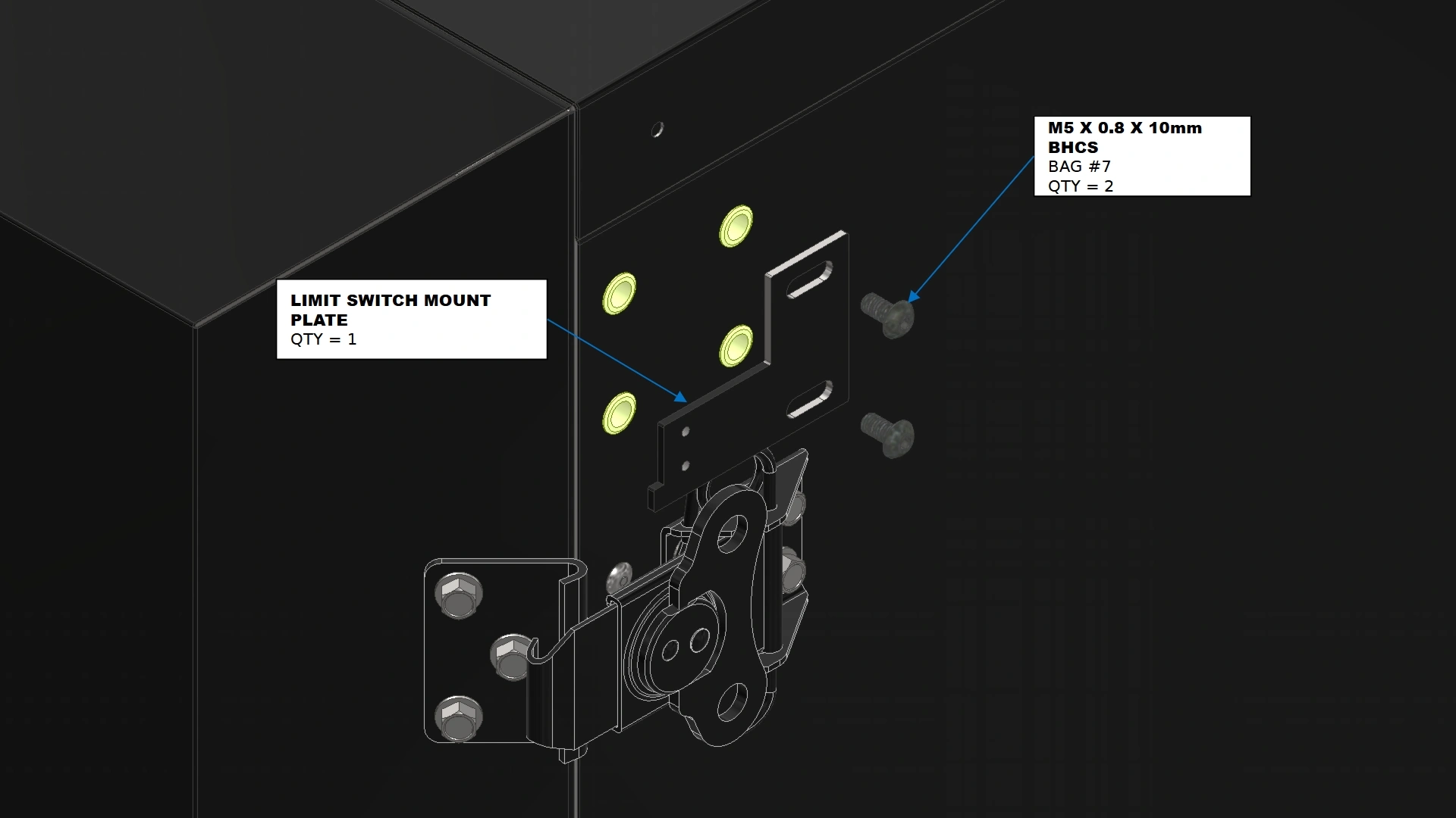
Parts
- (1) Limit Switch Mount Plate
Hardware
- (4) M5 x 0.8 x 10mm BHCS
Tools
- 3mm Hex Key
Instructions
- Locate the Limit Switch Mount Plate that came with your Vulcan 16 Hardware.
- Secure the plate onto the sidewall with the fasteners shown.
Materials
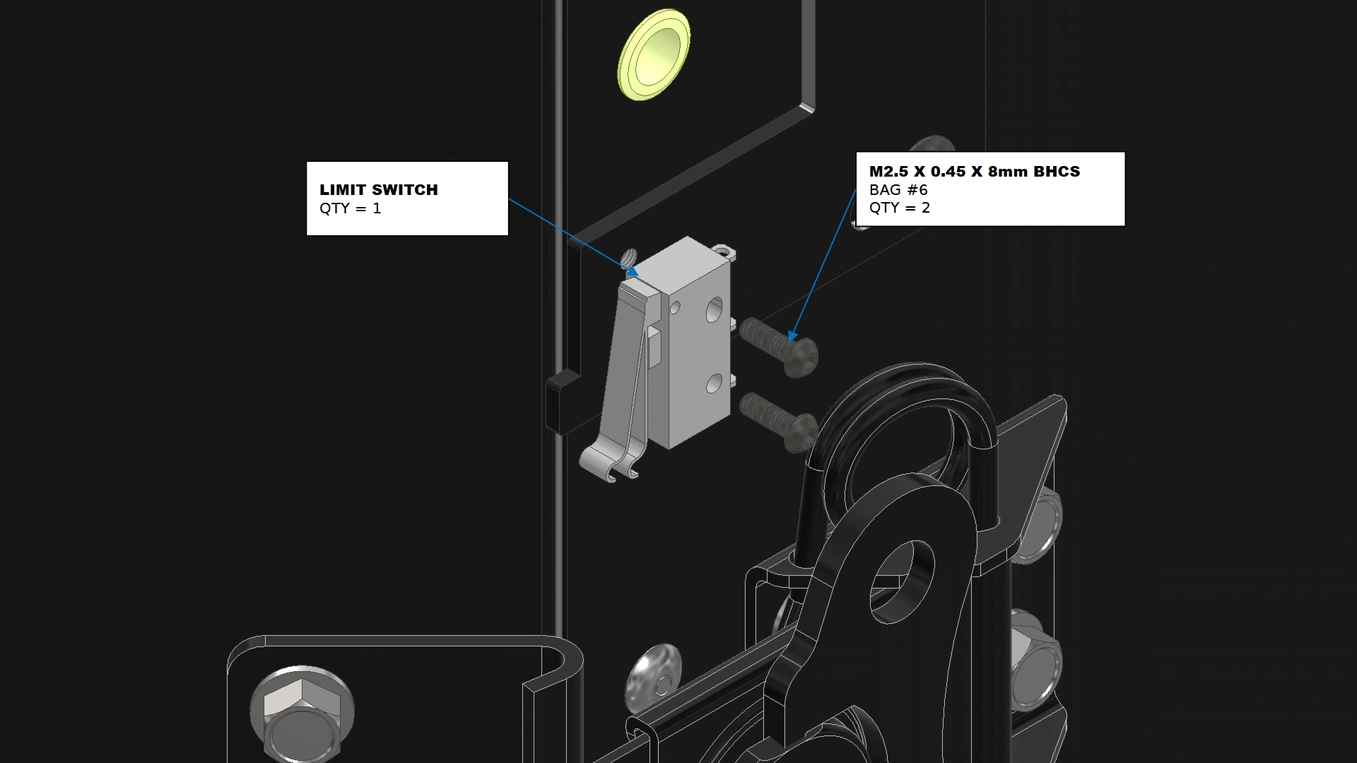
Parts
- (1) Limit Switch with Arm
Hardware
- (2) M2.5 x 0.45 x 8mm BHCS
Tools
- 1.5mm Hex Key
Instructions
- Locate the Limit Switch with Arm that came pre-installed inside of your Vulcan 16 Electronics Box.
- Secure the limit switch in place on the mounting plate with the fasteners shown.
Materials
Parts
- (1) Limit Switch Trigger Plate
Hardware
- (2) M5.5 x 19mm HHDS
Tools
- 8mm Hex Drive Socket
- Drill / Impact Driver
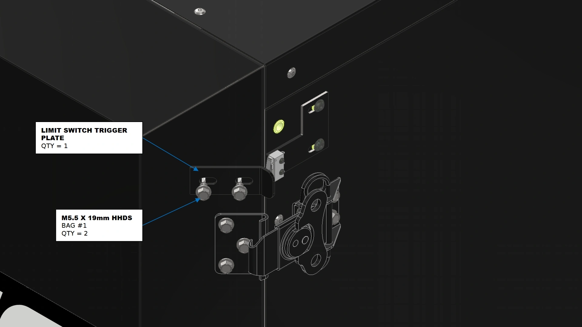
Instructions
- Locate the Limit Switch Trigger Plate that came with your Vulcan 16 Hardware.
- Close the door of the oven such that the latches are compressing the seal in the closed position.
- Secure the Limit Switch Trigger Plate to the door such that the switch is actuated by the flange in the door’s closed position. Adjust the plate’s position using the slot features as needed.
- Fully tighten the fasteners securing the the trigger plate.
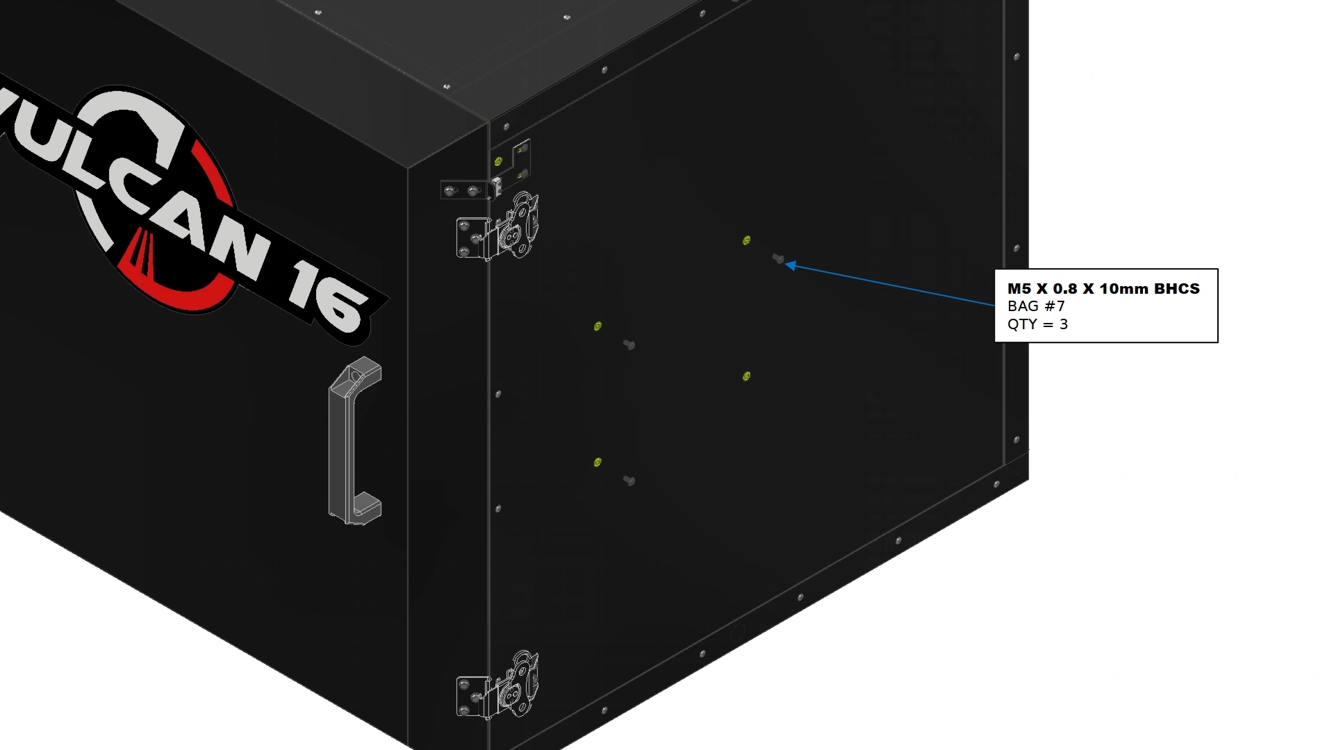
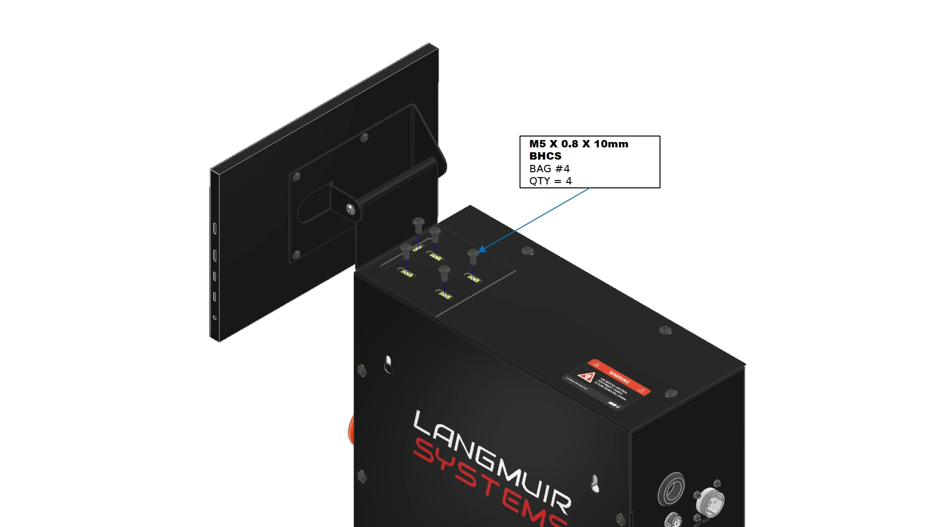
7. The Electronics Box
The next step in the assembly process is to mount the Electronics Enclosure.
Materials
Parts
- N/A
Hardware
- (3) M5 x 0.8 x 10mm BHCS
Tools
- 3mm Hex Key
Instructions
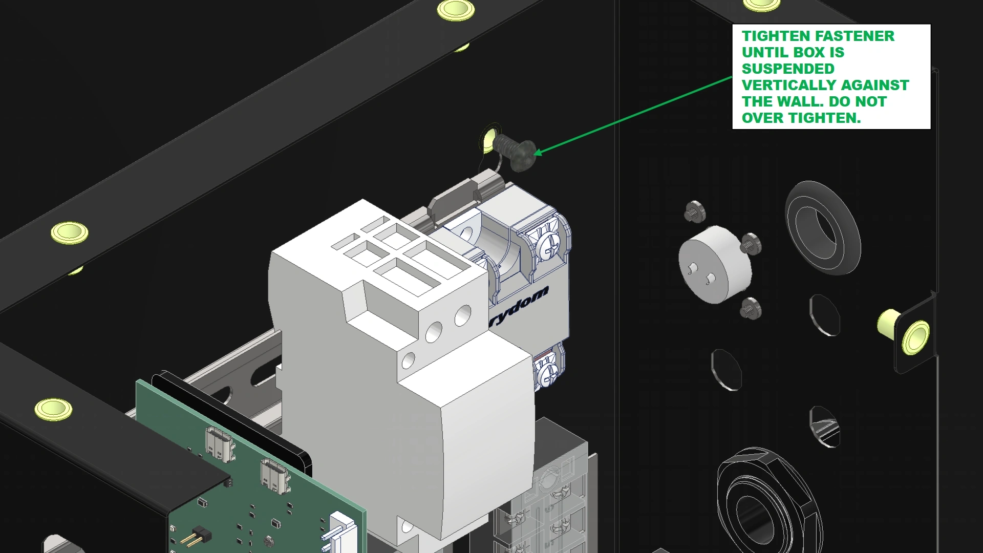
- Install the fasteners shown into the exposed rivet nuts located approximately halfway up the sidewall on the right hand side of the oven. Leave the head of the fastener slightly extended out.
Materials
Parts
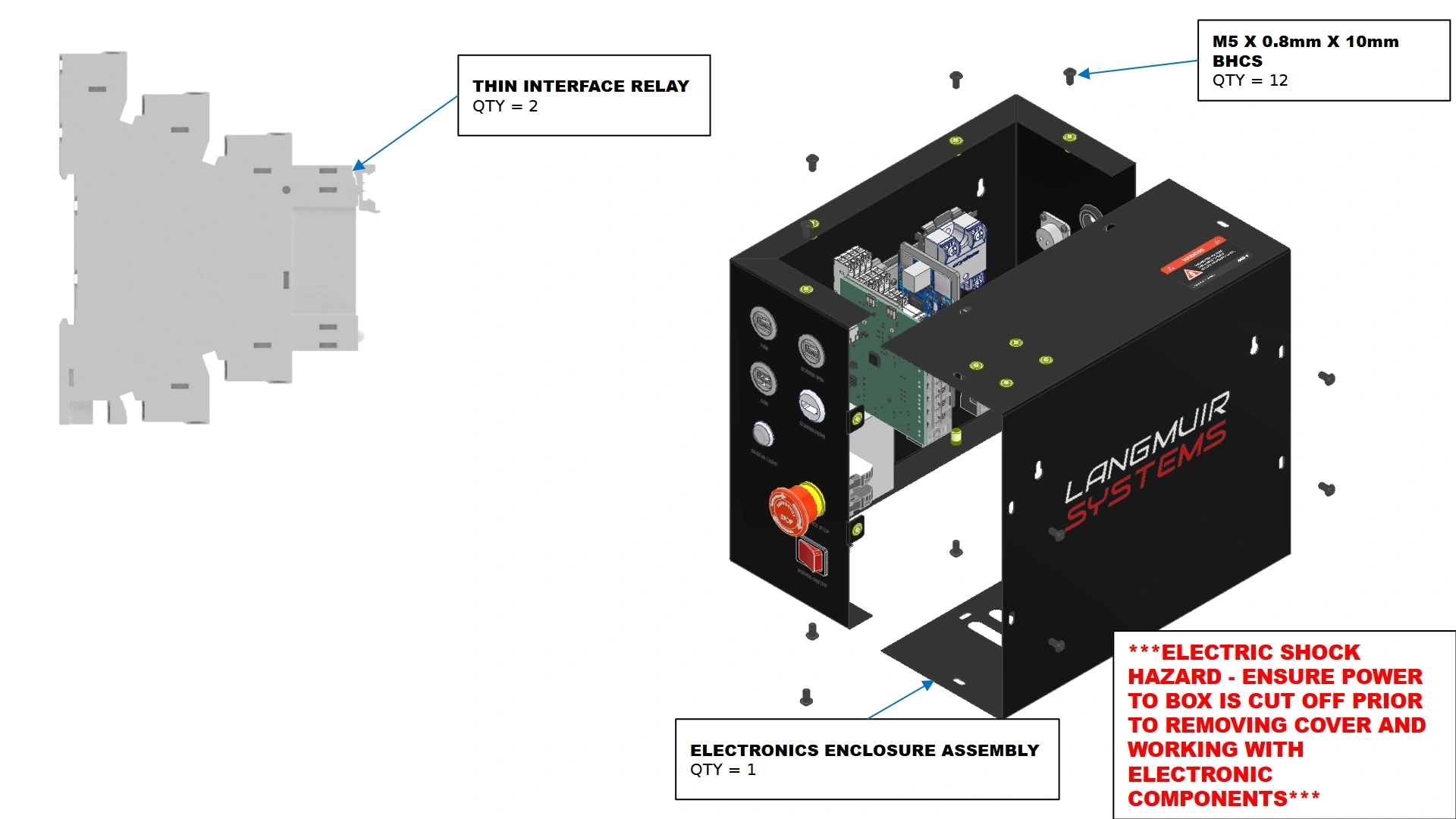
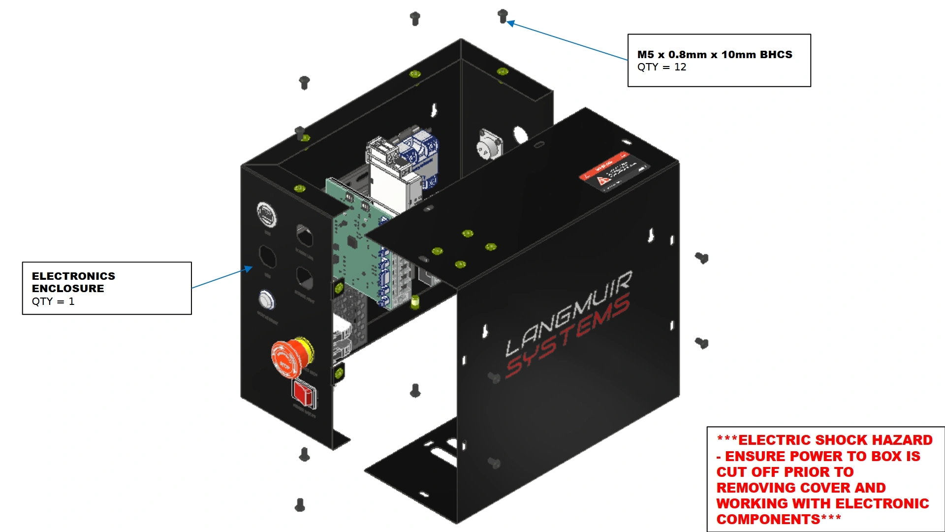
- (1) Electronics Enclosure Assembly
Hardware
- (12) M5 x 0.8 x 10mm BHCS
Tools
- 3mm Hex Key
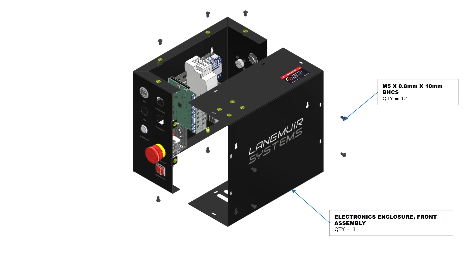
Instructions
- Locate the Electronics Enclosure Assembly that shipped with your unit.
- Using a 3mm Hex Key, remove the 12 M5 fasteners securing the Electronics Enclosure, Front Assembly in place. Set these fasteners aside to reinstall later.
Materials
Parts
- (1) Electronics Enclosure Assembly
Hardware
- (1) 18in Rubber Grommet Strip
Tools
- Scissors/Snips
- (Optional) Flat Head Screwdriver
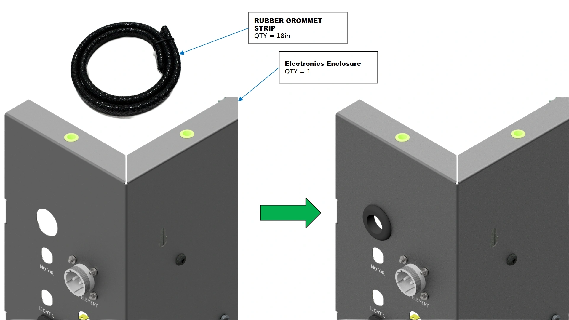
Instructions
- Locate the Rubber Grommet Strip that came with your unit.
- Using the full 18 inches of rubber strip, form one end to the unlabeled pass through in the back of the electronics enclosure and establish how much material will be required to line the circumference of the cutout.
- Cut the Rubber Grommet Strip to length.
NoteThe seal is impregnated with wire that is sharp if exposed. To avoid exposing the wire, make the cut between the raised ribs of the strip. Extra length of the strip is provided if your cut is not to your liking. Exposed wire can be removed with pliers.
- Install the strip along the circumference of the cutout. Take your time and, if needed, use a flat head screwdriver to assist seating the strip along the edge.
Materials
Parts
- (1) Electronics Enclosure Assembly (Front Panel Removed)
Hardware
- N/A
Tools
- N/A
Instructions
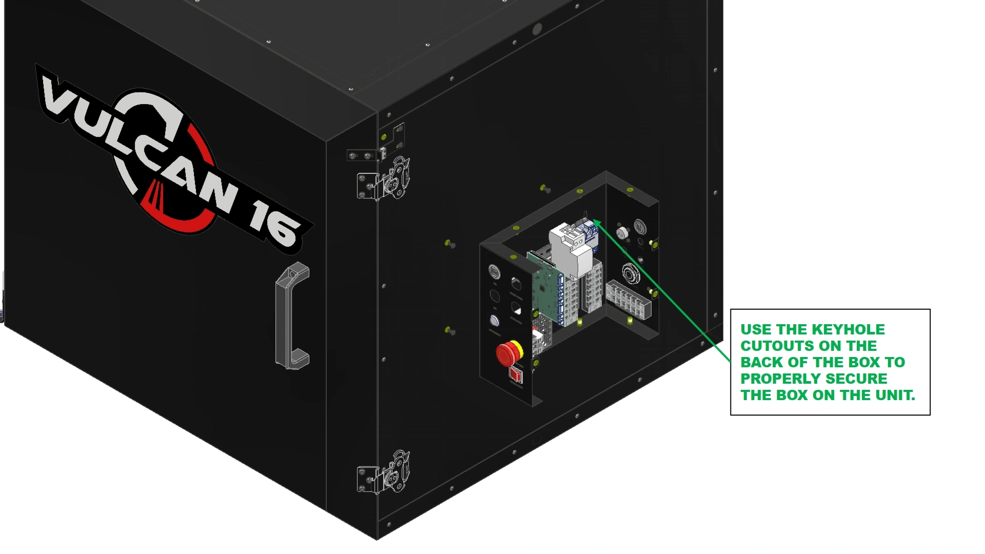
- Using the previously installed fasteners on the side of the unit from step A, mount the electronics enclosure using the provided Keyhole slots in the back of the box.
Materials
Parts
- (1) Electronics Enclosure Assembly
Hardware
- (3) M5 x 0.8 x 10mm
Tools
- 3mm Hex Key
Instructions
- Using a 3mm Hex Key, tighten the 3 mounting fasteners for the electronics box and secure the box to the unit.
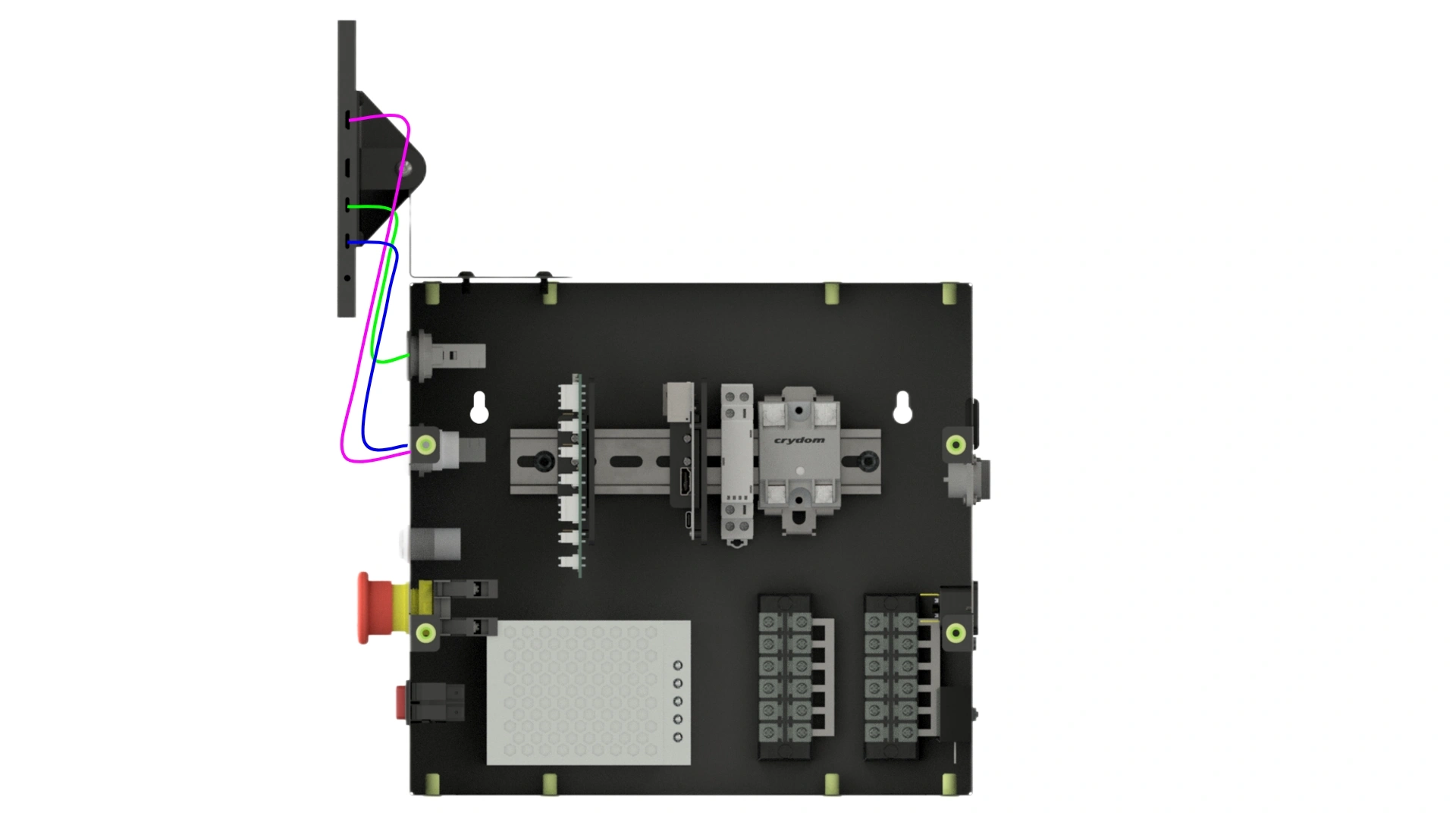
- Locate the two thermocouples and Harness-020 that came bundled inside the electronics closure and route them through the gasketed passthrough from step C.
Materials
Parts
- (1) Electronics Enclosure, Front Assembly
Hardware
- (12) M5 x 0.8 x 10mm BHCS
Tools
- 3mm Hex Key
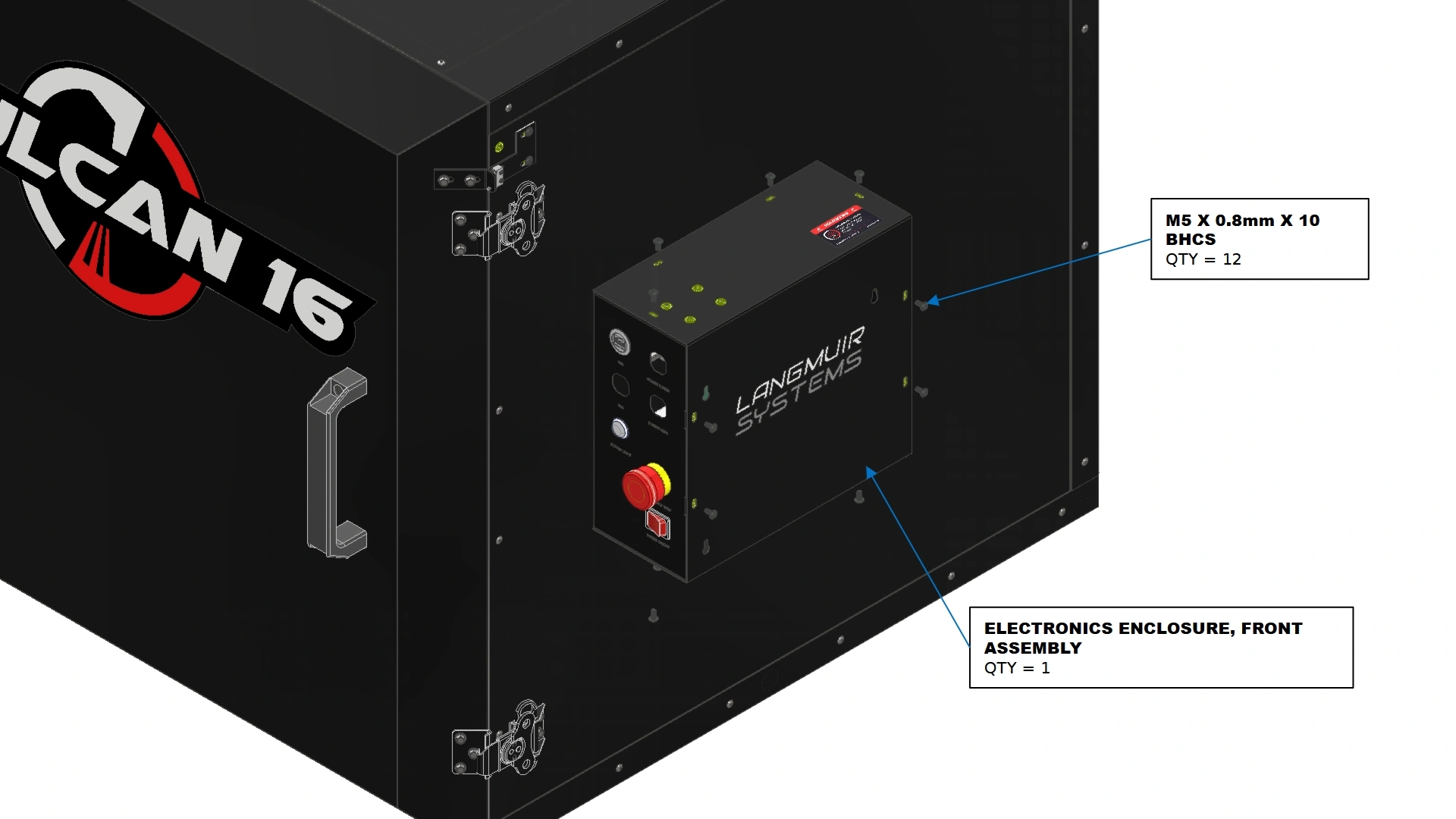
Instructions
- Locate the Electronics Enclosure, Front Assembly that you previously removed.
- Using a 3mm Hex Key, reinstall the twelve M5 fasteners previously set aside that secure the Electronics Enclosure, Front Assembly in place.
8. The Heating Element
Step eight of the assembly process is to fixture and mount the heating element to the unit.
Materials
Parts
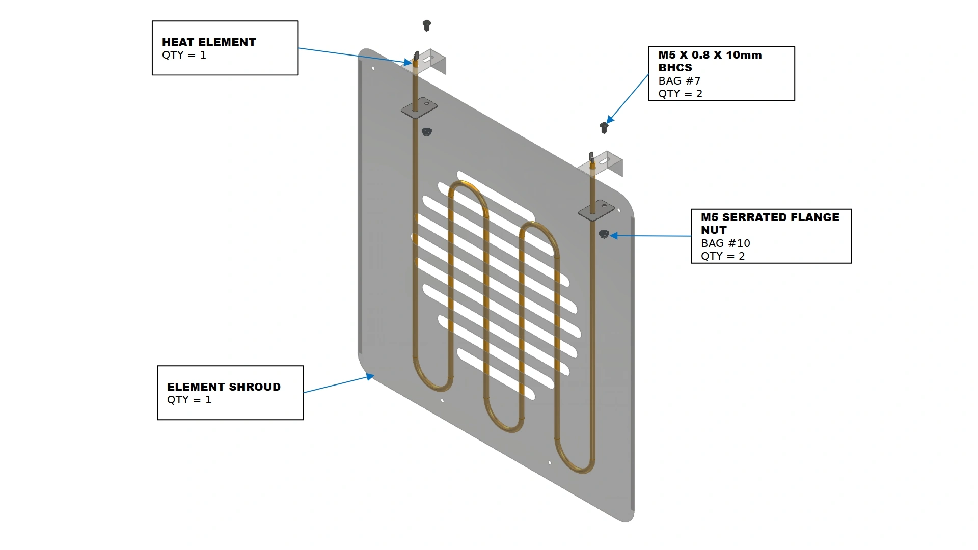
- (1) Heat Element
- (1) Element Shroud
Hardware
- (2) M5 x 0.8 x 10mm BHCS
- (2) M5 Serrated Flange Nuts
Tools
- 3mm Hex Key
Instructions
- Locate the Heat Element & Element Shroud that shipped with your unit.
- Route the ends of the heat element through the holes on the flanges of the shroud. Secure the heat element in place through the slot features with the provided fasteners shown.
Materials
Parts
- (1) Heat Element
- (1) Element Shroud
- (1) PCO-HARNESS-010
Hardware
- (4) M5.5 x 51mm SHROUD STANDOFF
- (4) M5.5 x 70mm HHDS
Tools
- Knife
- Wire Snips
- 8mm socket
- Drill or Impact Driver
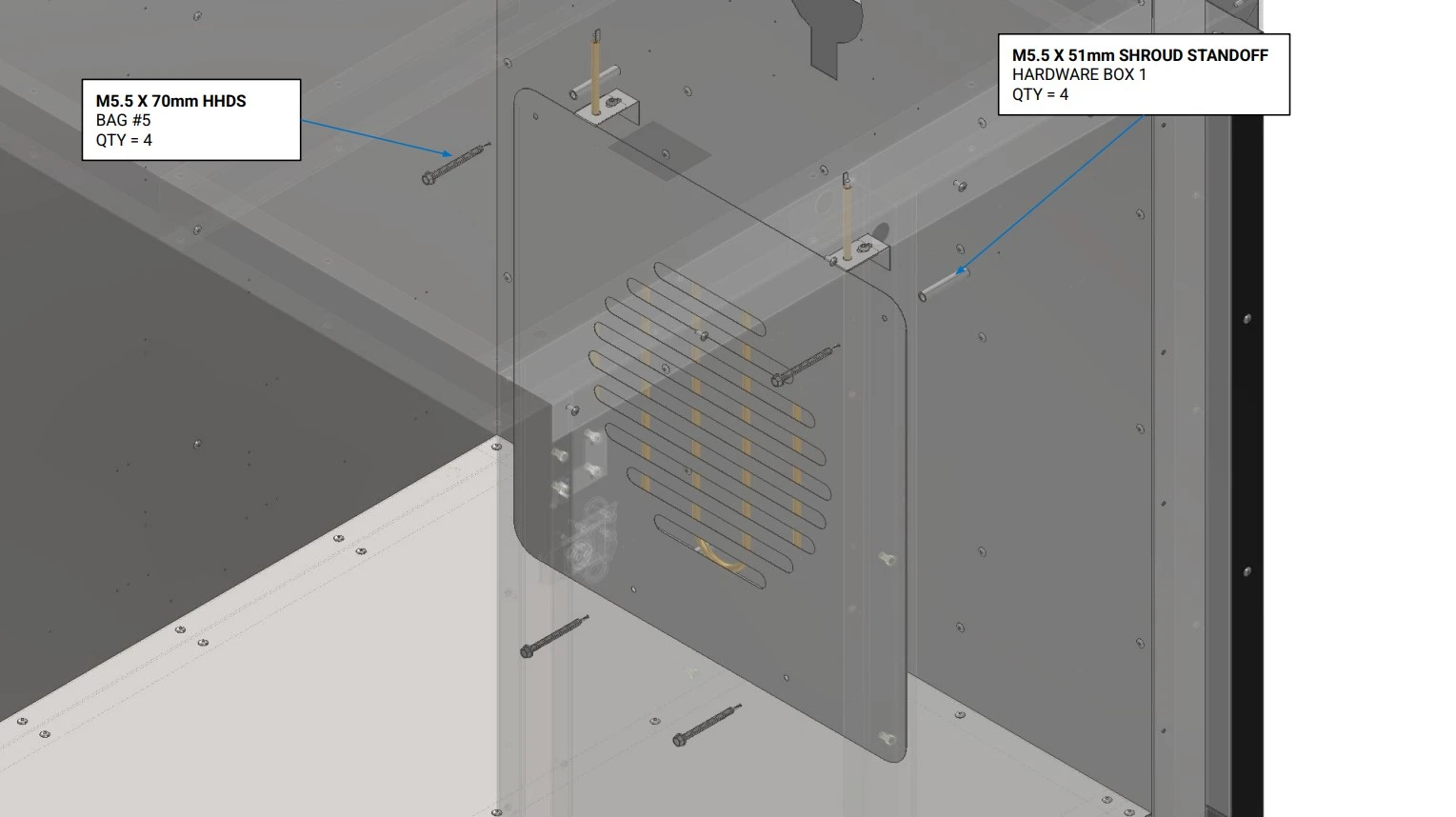
Instructions
- Using a knife and wire snips, cut a small opening in the exposed insulation of the rear wall at the bottom of the keyhole shaped cutout. The hole should be large enough to snake the element wire harness through the back of the oven.
ImportantExcessive Removal of insulation can affect the performance of the oven. Be diligent to keep the insulation intact and in place where necessary.NoteTo prevent insulation from entering the harness connector, it is recommended to use electrical tape on the end of the connector to shield any exposed connection points. Remember to remove the tape once the harness is properly routed.
- Using the spade terminal end of PCO-HARNESS-010, feed the element wire harness through the back side of the oven until the spade terminals can connect to the heat element. Do not connect the harness to the element at this time.
- Locate the four M5 x 51mm Shroud Standoffs and the fasteners shown.
- Using the pilot holes provided on the element shroud and the rear wall, secure the shroud and element to the rear wall of the unit as shown, using an 8mm socket and impact driver.
NoteThe element tubing should not be touching any metal surfaces after installation and during operation. If positioned correctly, the element shroud should be approximately 1.5 inches from the floor of the unit.
- Once secured on the wall, you may connect the spades of the heat element to the element wiring harness.
9. Final Covers
The next step in the assembly process is to secure any remaining covers in place.
Materials
Parts
- (1) SS MOTOR COVER PLATE
Hardware
- (4) M5.5 x 19mm HHDS
Tools
- 8mm socket
- Drill or Impact Driver
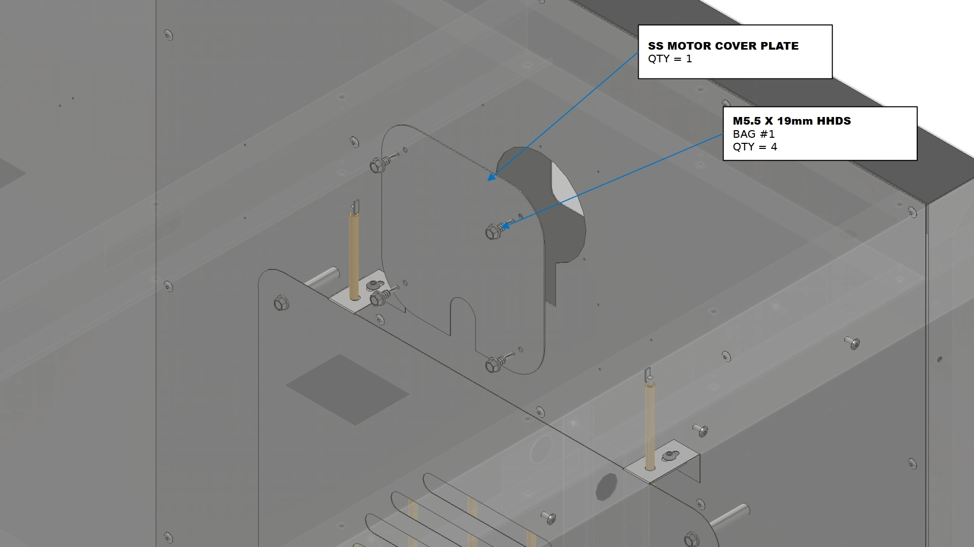
Instructions
IF YOU PURCHASED THE FAN KIT ADD-ON, SEE THE FAN KIT INSTALLATION GUIDE →
To improve oven heat retention, it is recommended to place a thin bead of Hi-Temp Gasket Sealant along the perimeter of the cover per the instructions defined by the sealant manufacturer.
For convenience, we strongly encourage you to use JB-WELD RED Hi-Temp RTV Sealant 10.3oz (Part Number 31914)
- Locate the SS Motor Cover Plate that came in your shipment.
- Using an 8mm socket and impact driver, install the SS Motor Cover Plate over the keyhole cutout in the rear wall using the fasteners shown such that the slotted cutout on the cover is pointed downward. Ensure that the heat element wire harness is properly fed through the slotted cutout. Pilot Hole locations have been provided on the rear wall to aide in aligning the cover.
Materials
Parts
- (1) MOTOR COVER PLATE
Hardware
- (4) M5.5 x 19mm HHDS
Tools
- 8mm socket
- Drill or Impact Driver
Instructions
To improve oven heat retention, it is recommended to place a thin bead of Hi-Temp Gasket Sealant along the perimeter of the cover per the instructions defined by the sealant manufacturer.
For convenience, we strongly encourage you to use our Vulcan Sealant Kit or JB-WELD RED Hi-Temp RTV Sealant 10.3oz (Part Number 31914)
- Locate the Motor Cover Plate that came in your shipment.
- Using an 8mm socket and impact driver, install the Motor Cover Plate over the rectangular cutout in the rear wall using the fasteners shown such that the slotted cutout on the cover is pointed downward. Ensure that the heat element wire harness is properly fed through the slotted cutout.
Materials
Parts
- (2) Light Socket Cover
Hardware
- (8) M5.5 x 19mm HHDS
Tools
- 8mm socket
- Drill or Impact Driver
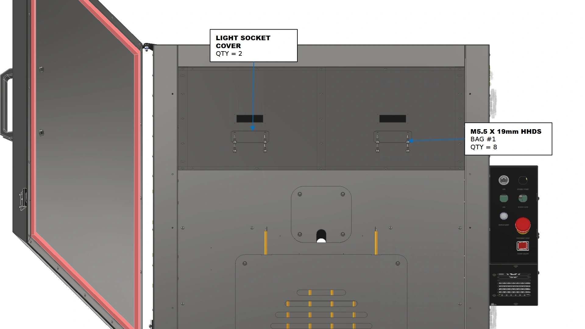
Instructions
IF YOU PURCHASED THE VULCAN LIGHT KIT ADD-ON, SEE THE OVEN LIGHT INSTALLATION GUIDE →
To improve oven heat retention, it is recommended to place a thin bead of Hi-Temp Gasket Sealant along the perimeter of the cover per the instructions defined by the sealant manufacturer.
For convenience, we strongly encourage you to use JB-WELD RED Hi-Temp RTV Sealant 10.3oz (Part Number 31914)
- Locate the two Light Socket Covers that were included with your shipment.
- Using an 8mm socket and impact driver, install both Light Socket Covers over the rectangular cutouts in the ceiling using the fasteners shown. Pilot Holes have been provided to aid in locating the covers.
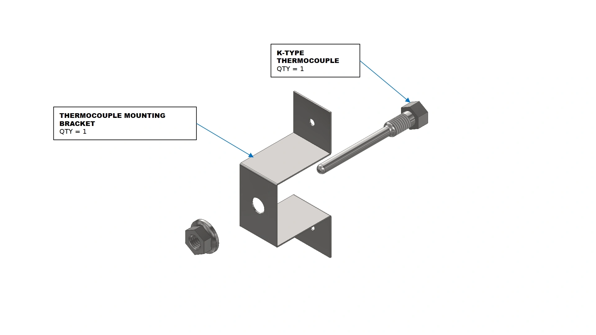
10. Thermocouple Installation
Step ten of the assembly process is determining where to place your thermocouples.
Materials
Parts
- (2) K-Type Thermocouples w/ M8 Nut
- (2) Thermocouple Mounting Brackets
- (2) M8 PTFE Washer
- (2) M8 PTFE Insulating Sleeve
Hardware
- N/A
Tools
- N/A
Instructions
- Locate the two K-Type thermocouples and the Thermocouple Mounting Bracket.
- Remove the M8 Nut on the thermocouple and install the probe end of the thermocouple through the insulating sleeve as shown and through the hole on the thermocouple mounting bracket.
- . Secure the Thermocouple to the mounting bracket with the previously removed M8 Nut and the M8 PTFE washer. It is critical that the thermocouple probe does not have contact with the metal of the mounting bracket.
- Repeat steps A1 - A3 for the second thermocouple.
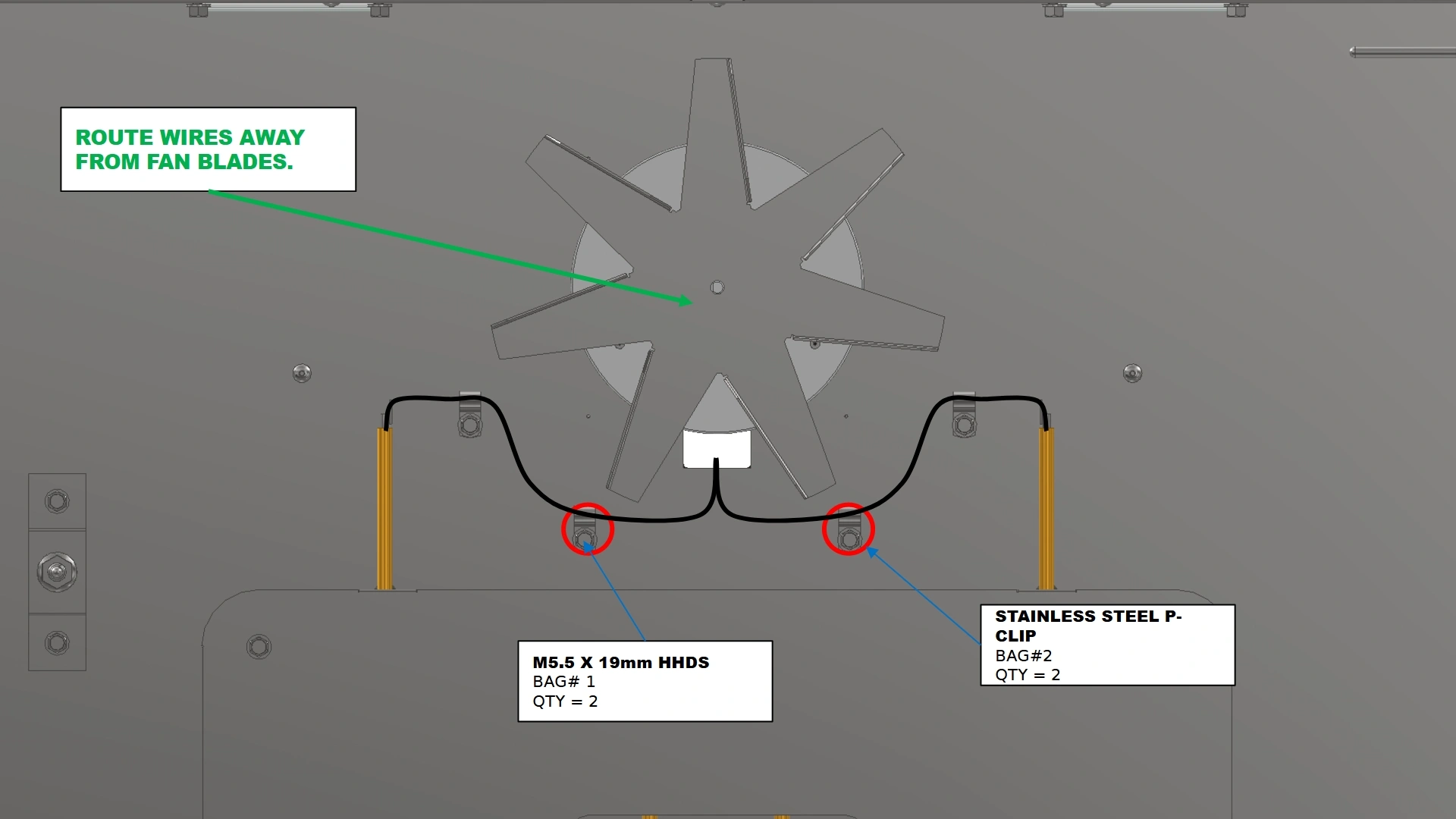
Materials
Parts
- (2) Thermocouple Mounting Assembly
- (2) Stainless Steel P-Clips
Hardware
- (8) M5.5 x 19mm HHDS
Tools
- 8mm socket
- Drill or Impact Driver
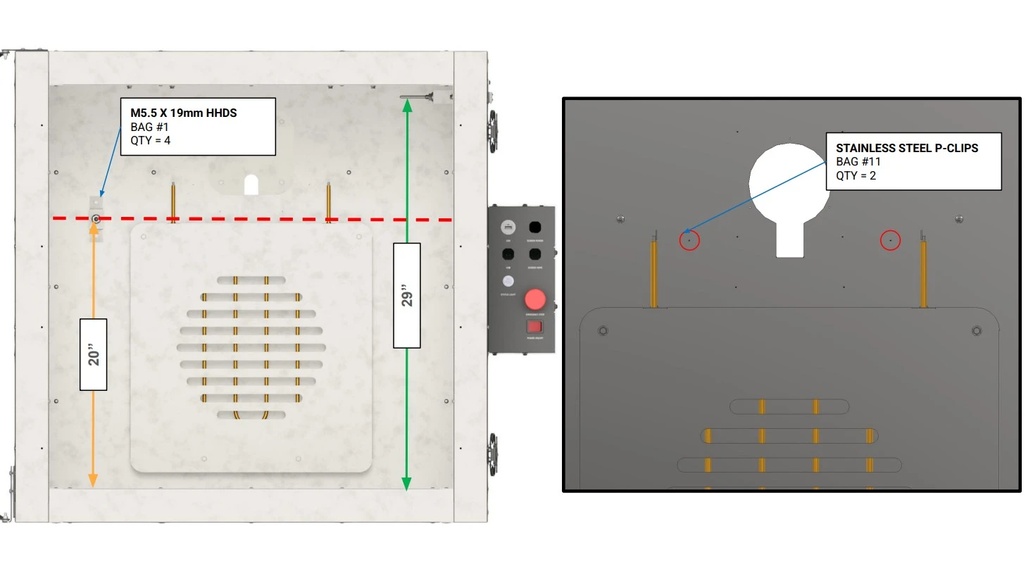
Instructions
- Using an 8mm socket and impact driver, secure the thermocouple mounting assemblies to the rear and side wall assemblies.
NotePilot holes have been provided on the rear and sidewall assemblies for proper placement of the thermocouples. Reference the provided images to locate the provided pilot holes.
- Route the thermocouple wire leads through the same passthrough as the heat element cables.
- Using the provided P-Clips and M5.5 x 19mm HHDS fasteners, secure the thermocouple wire leads away from the curing area using the highlighted cable management pilot holes.
NoteEnsure the thermocouple wire leads do not make contact with the connection point of the heat element as this can create a short in the electronics and a potential shock hazard.
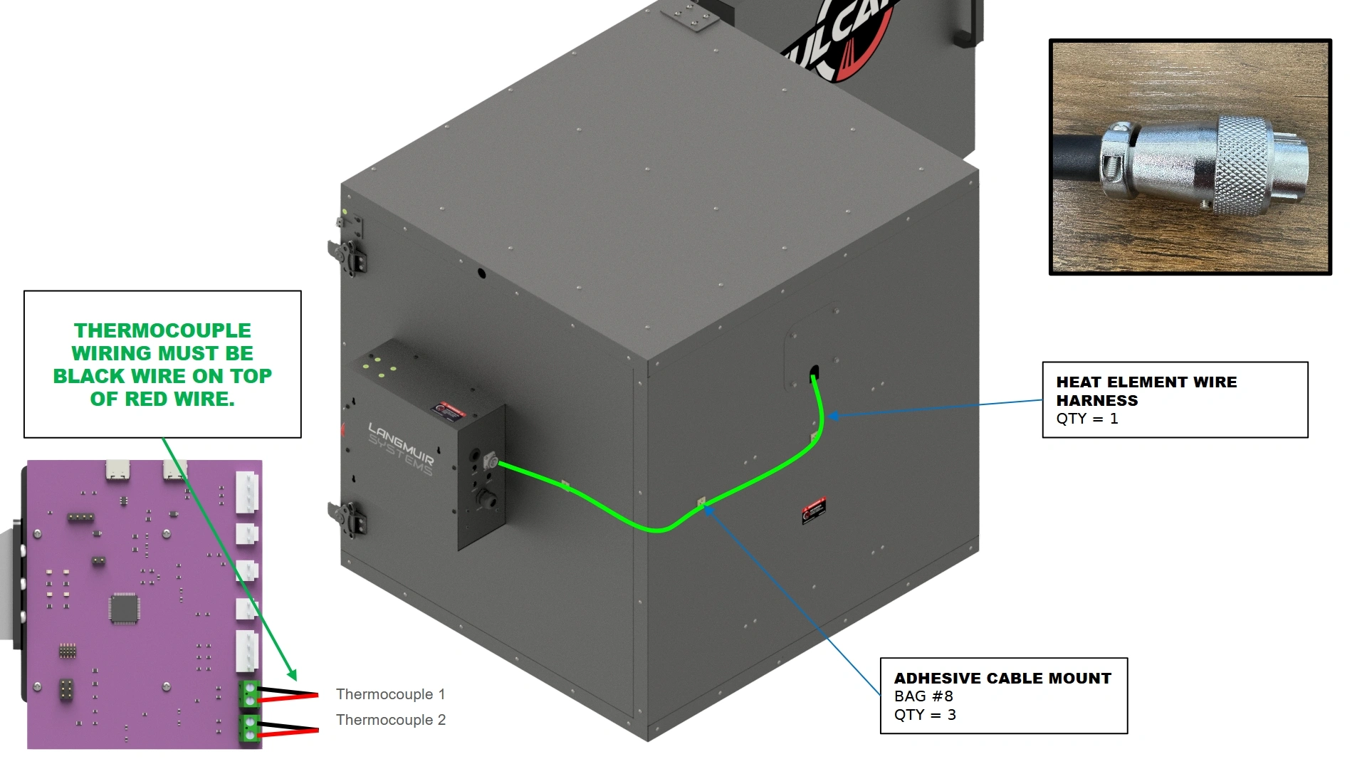
11. Wiring
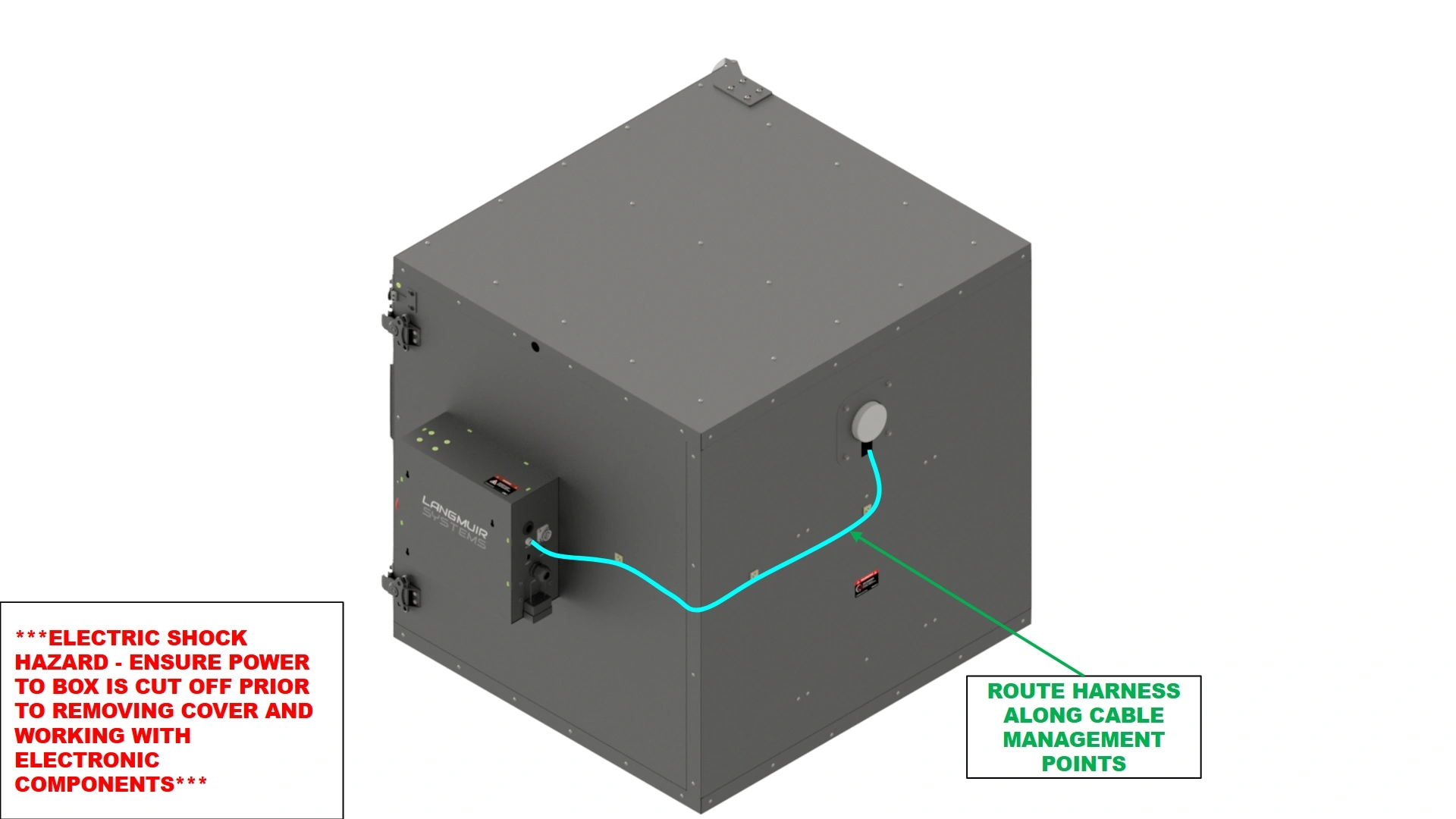
The final step in the assembly process is to route the wiring harnesses to the back of the electronics enclosure
Materials
Parts
- (1) Heat Element Wire Harness
Hardware
- (3) Adhesive Cable Mount
- (3) Cable Ties
Tools
- ⅛” Tip Flathead screwdriver
- (Optional) Isopropyl alcohol
- (Optional) Microfiber Towel
Instructions
- Locate the Adhesive Backed Cable Mounts.
- Plug the element wire harness that was previously fed through the unit into the back of the electronics enclosure.
- Ensure that the wiring of the thermocouples is correct with the black wire in the upper screw terminal for both thermal couples.
- Using cable ties and the adhesive backed cable mounts, secure the harnesses to the unit to prevent any sag.
Important
It is recommended to install the adhesive backed cable mounts without any load to allow for proper adhesion. Apply firm, even pressure for best results.
Note
Cleaning the sheet metal surfaces with rubbing alcohol prior to applying the adhesive mounts will improve adhesion.
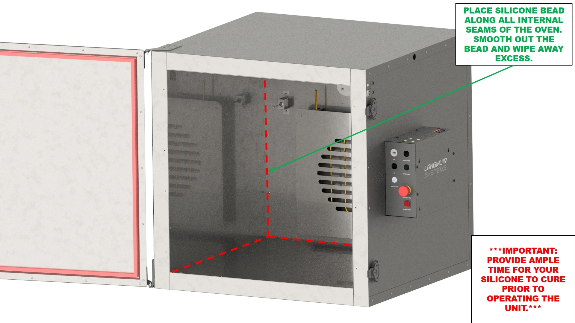
12. (Optional) Sealant
To optimize oven performance, users can opt to seal the assembled oven with Hi-Temp sealant.
Materials
Parts
- N/A
Hardware
- N/A
Tools
- Hi-Temp Gasket Sealer/Caulk
- Caulking Gun
- Degreaser or Isopropyl alcohol
- Microfiber Cloth or Shop Towel
- (Optional) Gloves
- (Optional) Caulk Finishing Tool
Instructions
- Locate a tube of 10oz Hi-Temp Gasket Maker and a Degreasing Agent such as rubbing alcohol.
For your convenience, we strongly recommend the use of JB Weld’s Red High Temperature RTV Silicone Gasket Maker and Sealant (Part Number: 31914).
- Using a degreaser and towel, wipe down all internal surfaces within 1” of any internal seams of the unit. The surface should be free of any residue before moving on to the next step.
ImportantFailure to clean the surfaces properly can result in a poor seal and reduce effectiveness of the sealant.
- Using a Caulking Gun with the Hi-Temp Sealant, apply a 0.25” bead to the internal seams of the oven.
- Once applied, use your finger or a caulk finishing tool to push the Caulk into the seam and create a professional looking seal.
- Wipe away any excess sealant left on the walls.
ImportantDo NOT operate the oven until the sealant is given ample time to cure. Curing times of sealants can vary by manufacturer so be sure to reference your sealant instructions prior to operating the oven for the first time.
13. Startup Awareness
Initial use of the Vulcan 16 should be done with care to ensure you are familiar with the unit.
Materials
Parts
- N/A
Hardware
- N/A
Tools
- N/A
Instructions
FIRE HAZARD
THE FIRST 3-5 HEAT CYCLES OF THE VULCAN 16 MAY PRODUCE
LIGHT SMOKE DUE TO OFF-GASSING OF MOISTURE FROM THE UNIT AS WELL
AS INTERNAL OILS FROM THE METALLIC SHELL. IT IS RECOMMENDED TO
PERFORM THE FIRST HEAT CYCLES IN A WELL-VENTILATED AREA UNTIL
THERE IS NO NOTICEABLE OFF-GASSING. FOR YOUR SAFETY, IT IS
RECOMMENDED TO HAVE A FIRE EXTINGUISHER NEARBY IN THE EVENT OF A
FIRE.
HOT MATERIALS
ALL ITEMS INSIDE THE VULCAN 16 SHOULD BE HANDLED WITH
CAUTION AS TO NOT BURN ONESELF. HEAT CYCLES FOR NEW FIXTURING
WILL ALSO OFF-GAS AND MAY HAVE RESIDUAL OIL AFTER HEATING UP. TAKE
EXTRA CAUTION WHEN HANDLING NEW FIXTURING.

ELECTRICAL SHOCK
BEFORE STARTING YOUR VULCAN 16, ALWAYS ENSURE THE
EXPOSED LEADS OF THE HEAT ELEMENT ARE NOT IN CONTACT WITH
THERMOCOUPLE WIRES AND THAT THE HEAT ELEMENT HARNESS IS
SITUATED AT A SAFE DISTANCE FROM THE FAN KIT IF INSTALLED.
Vulcan Fan Kit Add-on
Images in this Guide
The assembly drawings and pictures included in this guide can be expanded to
full-screen and zoomed to provide more detail on a given step.
1: Preparing the Motor
The first step to install the fan kit is to prepare it for installation.
Materials
Parts
- (1) Motor w/ Fan Blade
Hardware
- N/A
Tools
- 10mm Socket Wrench
Instructions
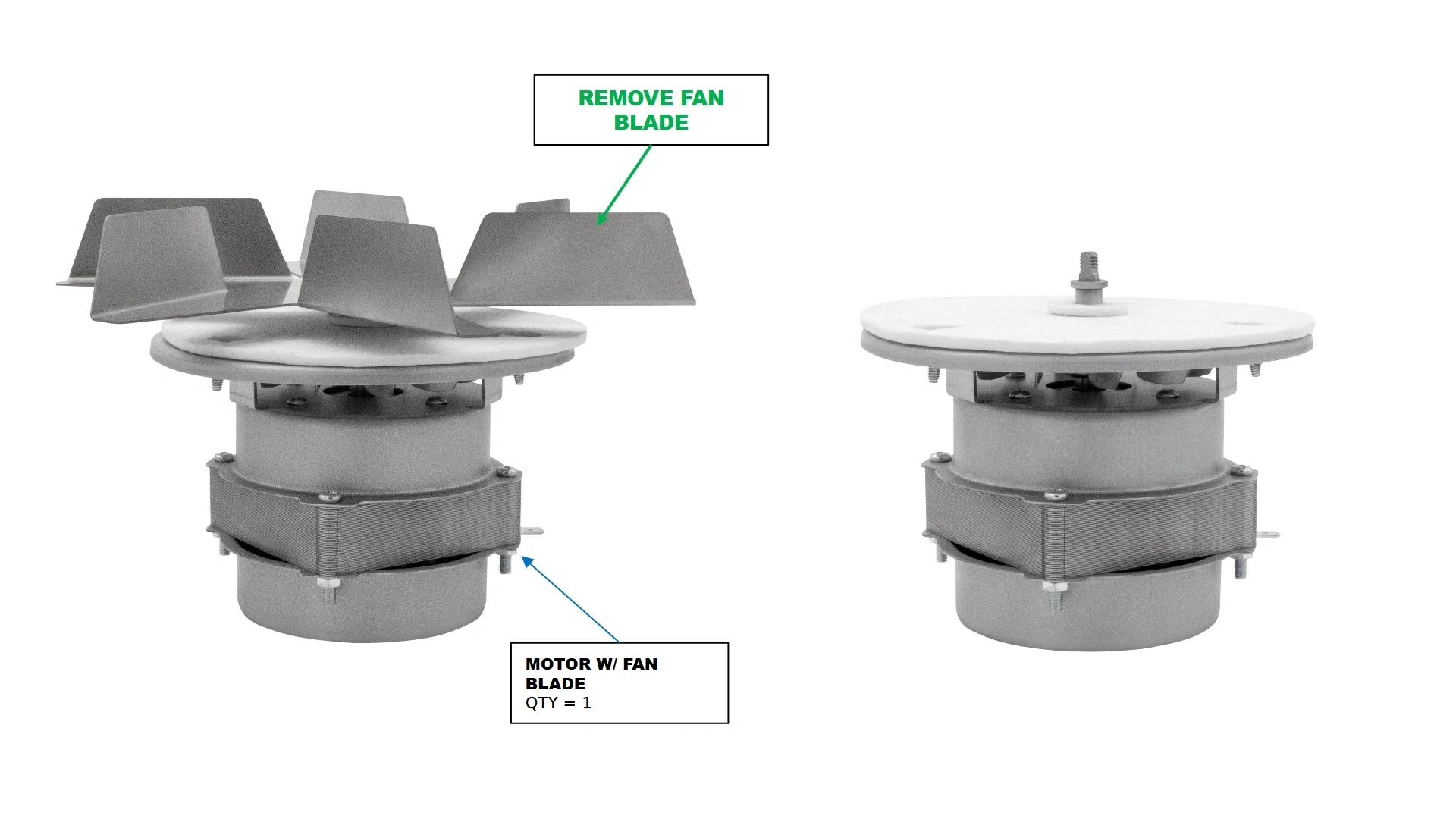
- Locate the Motor w/ Fan Blade that came with your kit.
- Using a socket wrench, remove the 10mm nut that secures the fan blade to the motor shaft and set aside for later.
- Remove the Fan Blade and set aside for reinstallation later.
Materials
Parts
- (1) Motor w/ Fan Blade
Hardware
- N/A
Tools
- N/A
Instructions
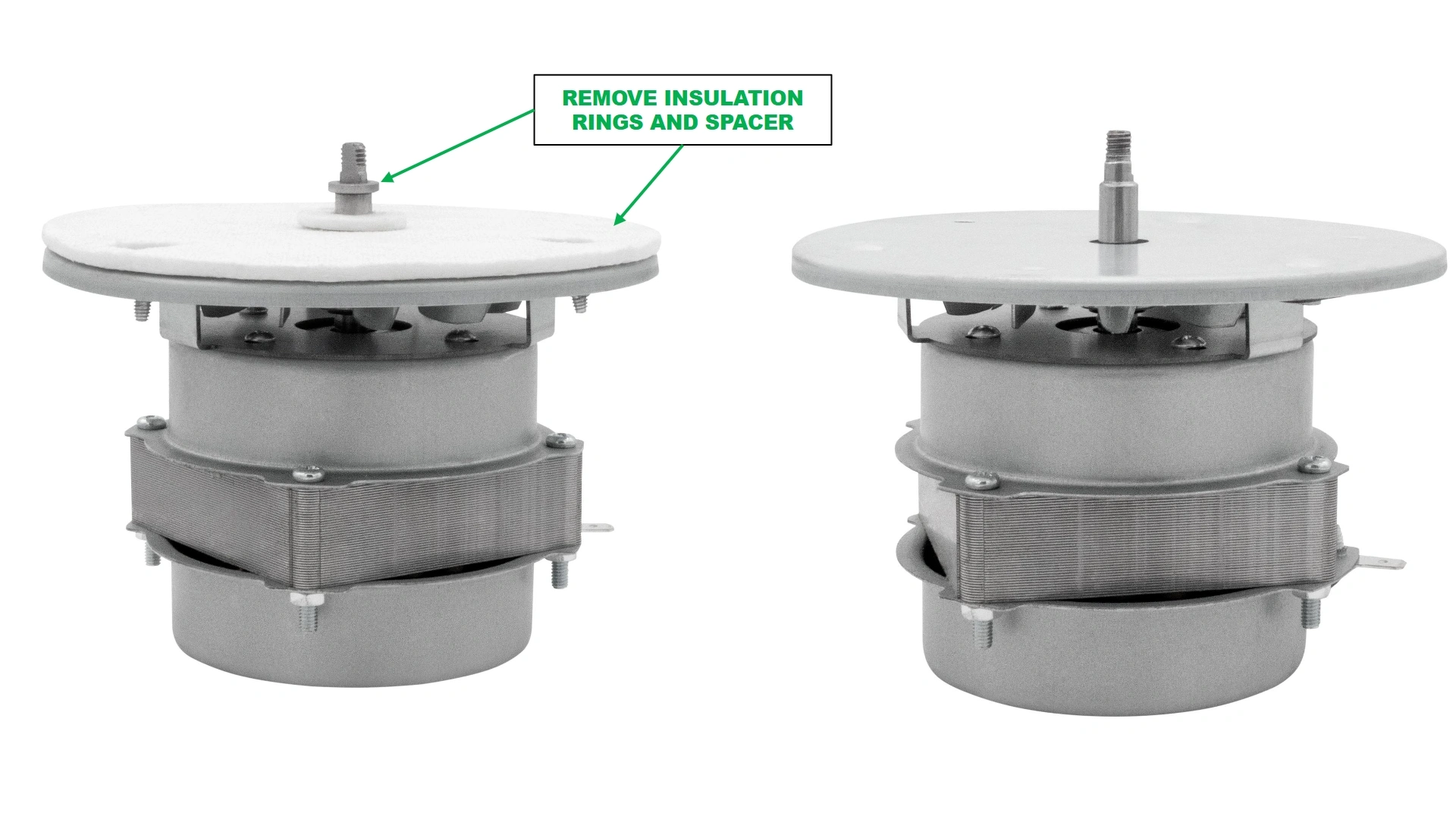
- Remove the shaft spacer, and the two insulation pads provided with the motor and set aside for later.
Materials
Parts
- (1) Motor w/ Fan Blade
Hardware
- N/A
Tools
- #1 Phillips Head Screwdriver
Instructions
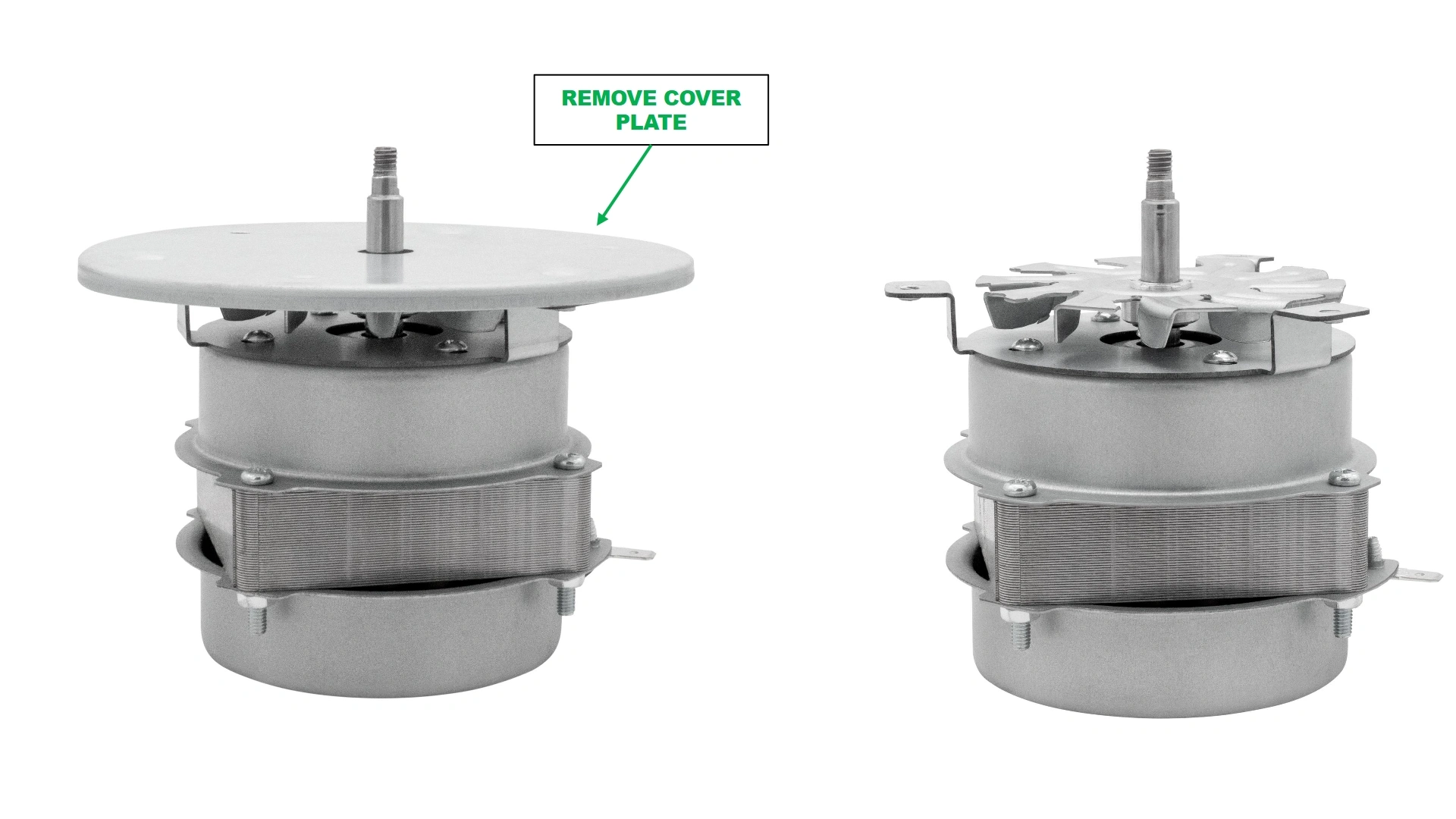
- Using a #2 phillips head screwdriver, remove the mounting plate of the motor and set aside with the fasteners for reinstallation.
- Set the disassembled motor aside.
Materials
Parts
- (1) Motor w/ Fan Blade
Hardware
- N/A
Tools
- N/A
Instructions
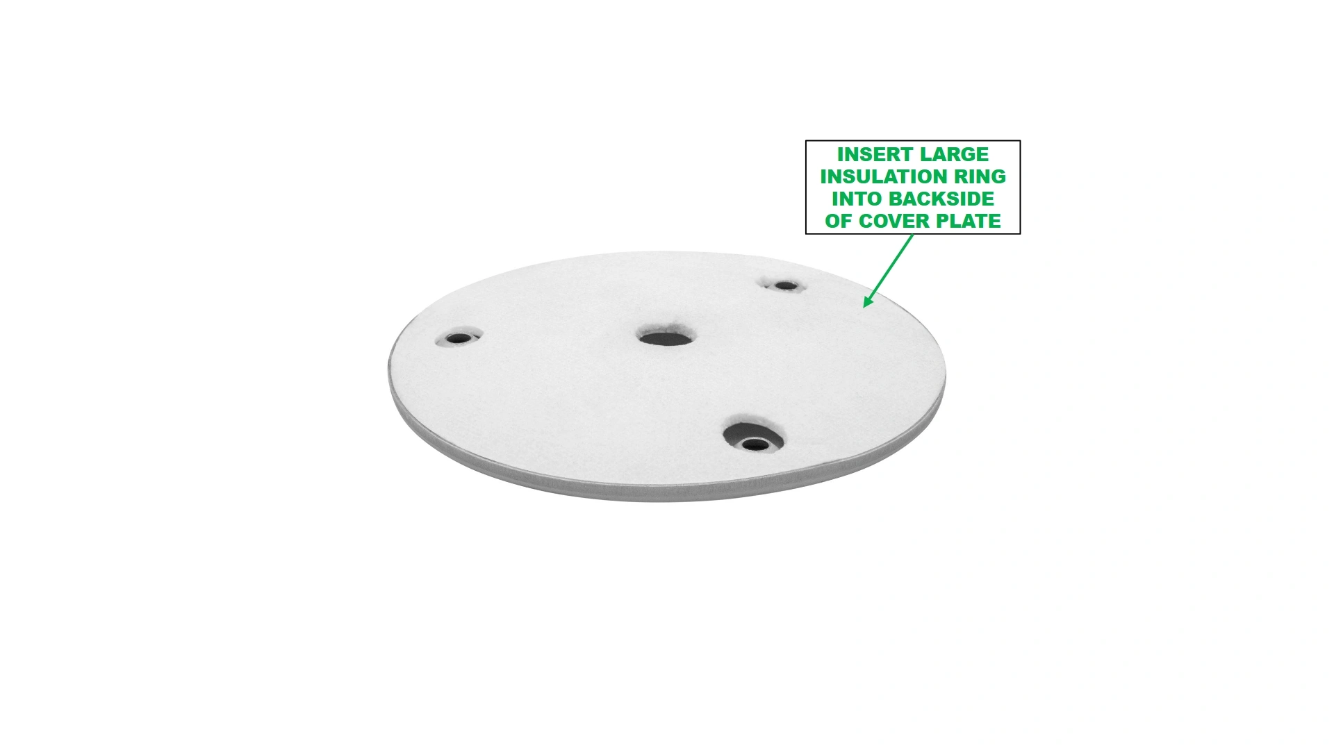
- Locate the large insulation ring removed in step B1.
- Place the large insulation pad inside the back of the removed motor cover plate, making sure the holes are aligned with the dimpled clearance holes of the plate.
2: Preparing the Oven
The second step to install the fan kit is to prepare the installation site.
Materials
Parts
- N/A
Hardware
- N/A
Tools
- Knife
- Wire Snips
- 8mm Socket
- Socket Wrench
Instructions
ELECTRICAL SHOCK
Ensure power to the Vulcan 16 is disconnected before working around or handling electrical equipment for the Vulcan.
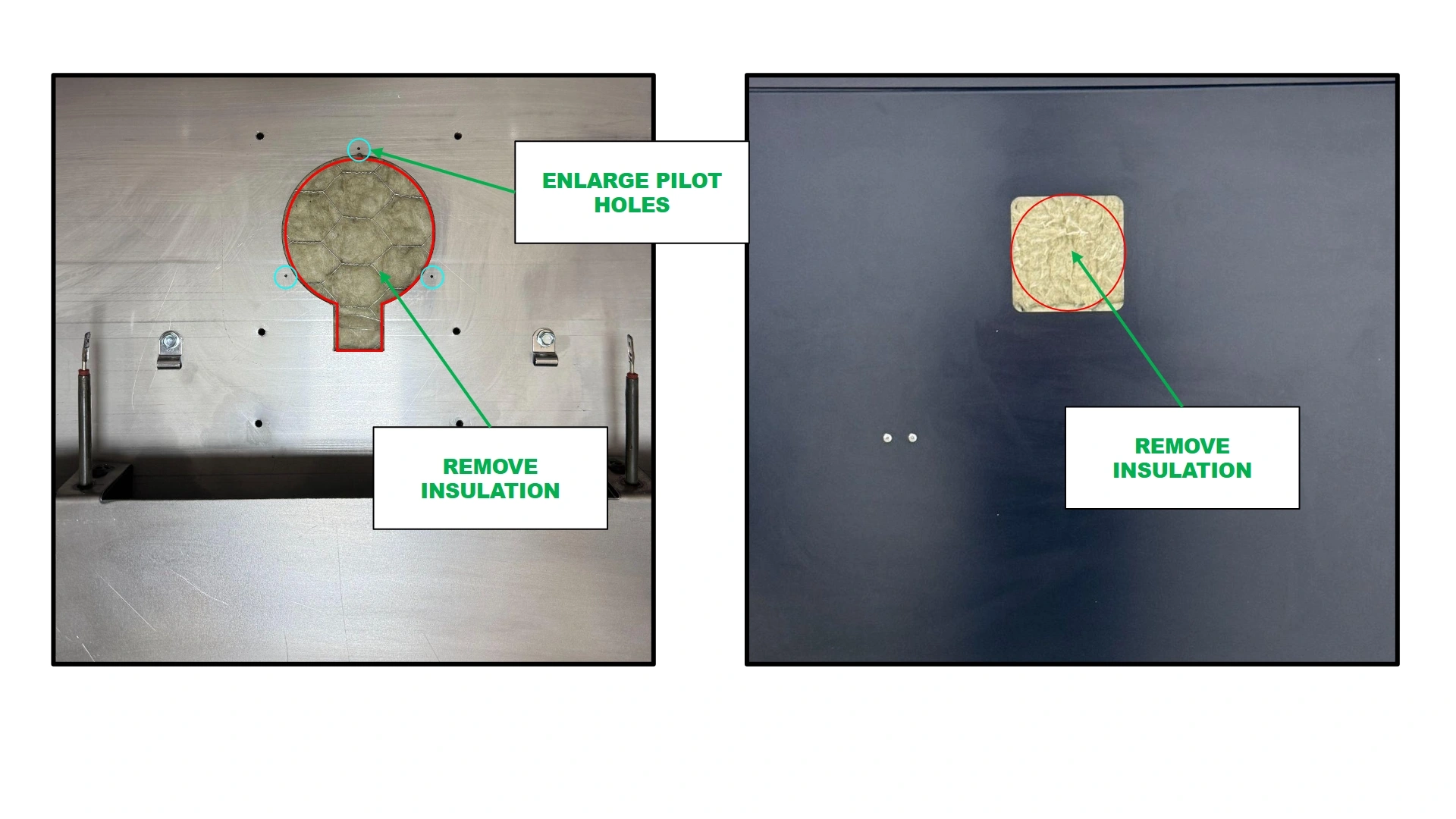
- If installed, remove both the inner Stainless Steel Motor Cover Plate & the outer Motor Cover Plate that are installed on the unit. Also disconnect the heat element wiring harness from the element if previously installed.
- Using a knife and wire snips, remove all insulation in the back wall, indicated by the red outline, that is blocking the installation of the motor.
- The final void cutout should extend through to the back wall as a circle that is tangent on all side to the square cutout in the back of the unit.
- Using a #16 carbide drill bit, bore out the holes identified in blue in the image above to allow the motor’s mounting plate fasteners from Step 1, Part C to pass through and thread to the motor flanges.
3: Installing the motor
The next step is to install the fan motor into the rear wall assembly.
Materials
Parts
- (1) Motor (disassembled)
Hardware
- N/A
Tools
- Knife
- Wire Snips
Instructions
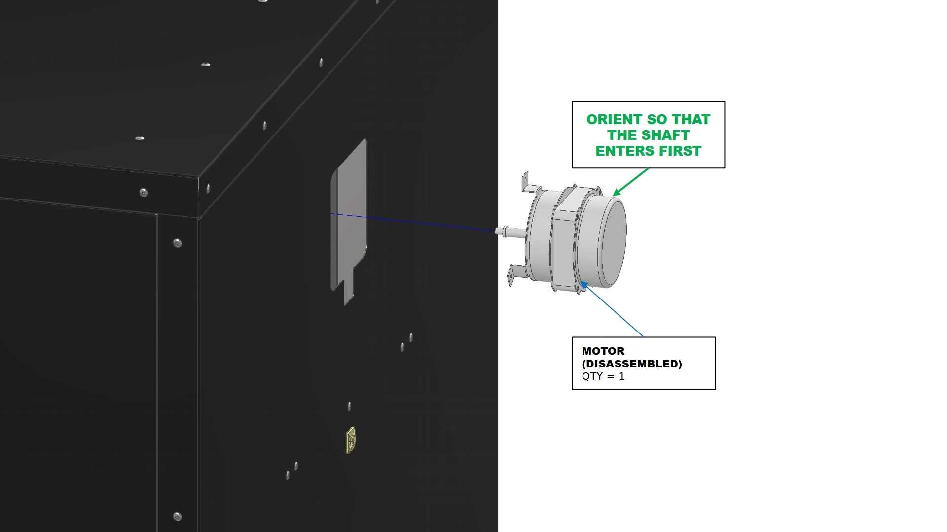
- Locate the disassembled motor from step 1.
- From the backside of the unit, insert the motor into the wall where you removed the insulation. Ensure that you do not need to remove additional insulation.
Materials
Parts
- (1) Motor (disassembled)
Hardware
- N/A
Tools
- N/A
Instructions
IMPORTANT
Ensure that the 3 mounting flanges of the motor do not have insulation blocking the threaded holes.
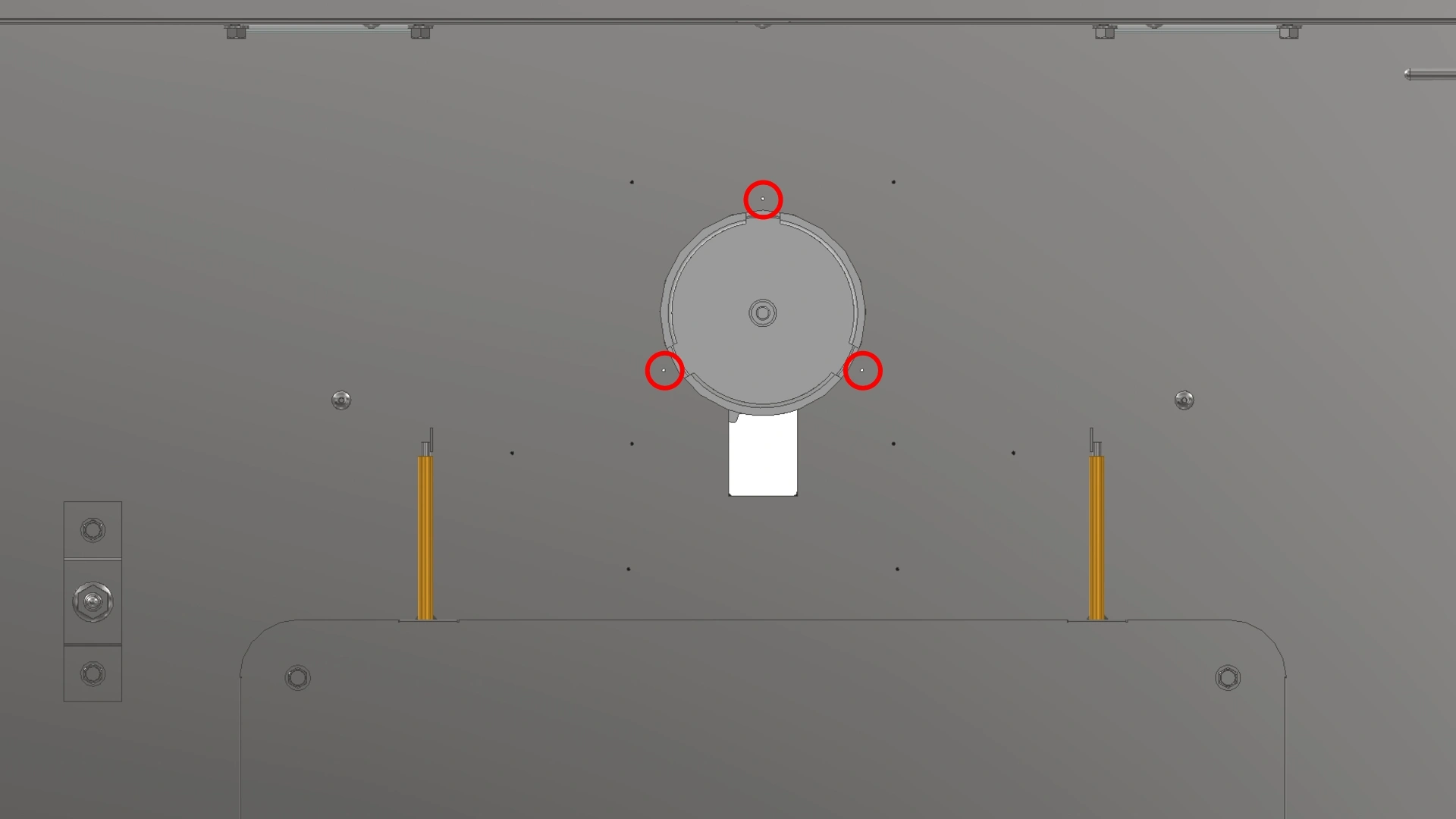
- Once placed in the rear wall, allow the remaining insulation to hold the motor in place as you transition to the inside of the Vulcan.
- Once inside, ensure that the motor is oriented such that the mounting points on the motor align with the circled hole pattern shown and that the cable for the motor extends straight down from the back of the Vulcan.
Materials
Parts
- (1) Motor
- (1) Cover Plate with Insulation
Hardware
- (3) M4 x 0.7 Screws (Previously Removed)
Tools
- #2 Phillips Head Screwdriver
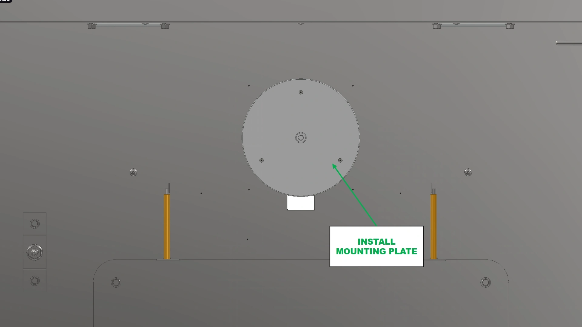
Instructions
- Place the motor cover plate with insulation onto the shaft as if going to reinstall. Pull slightly on the motor shaft to bring the motor against the wall and aide in aligning the screw holes.
NoteIt is much easier to align the mounting holes of the motor to the rear wall with an additional set of hands. Have a helper hold the motor in place from the rear side of the Vulcan as you secure it using the provided screws.
- Secure the motor to the rear wall with the motor cover plate using the 3 M4 x 0.7 screws removed during disassembly.
Materials
Parts
- (1) Motor w/ plate
- (1) Fan Blade
Hardware
- (1) Shaft Spacer (Previously Removed)
- (1) 10mm Nut (Previously Removed)
- (1) Washer (Previously Removed)
Tools
- 10mm Socket
- Socket Wrench
Instructions
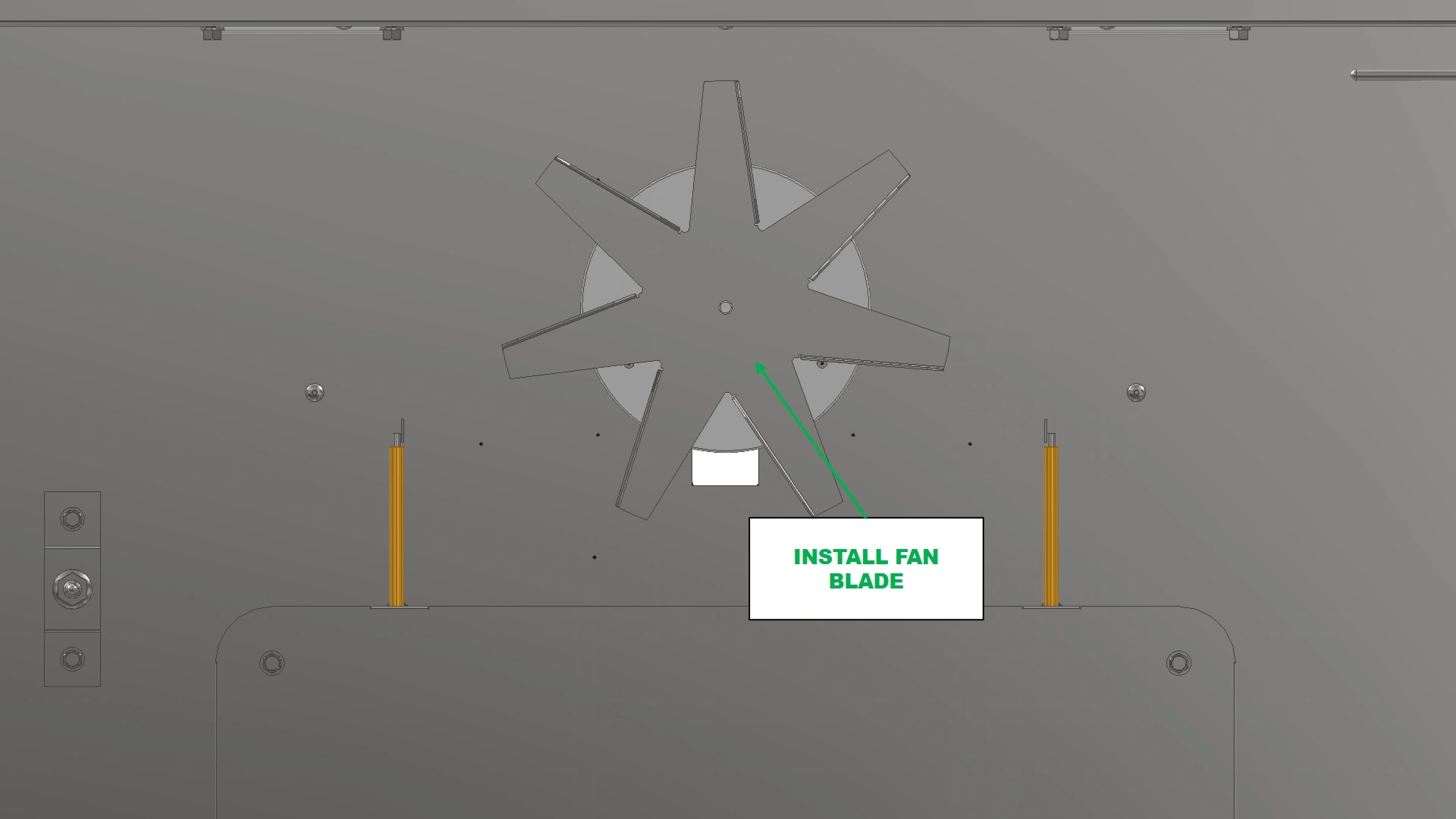
- Reinstall the shaft spacer on the shaft.
- Secure the fan blade onto the shaft with the 10mm Nut and washer that came with the motor.
4: Installing the covers
The next step is to install the Motor Mount Cover on the backside of the Vulcan.
Materials
Parts
- (1) Motor Mount Plate
Hardware
- (4) M5.5 x 19mm HHDS
Tools
- 8mm Socket Driver
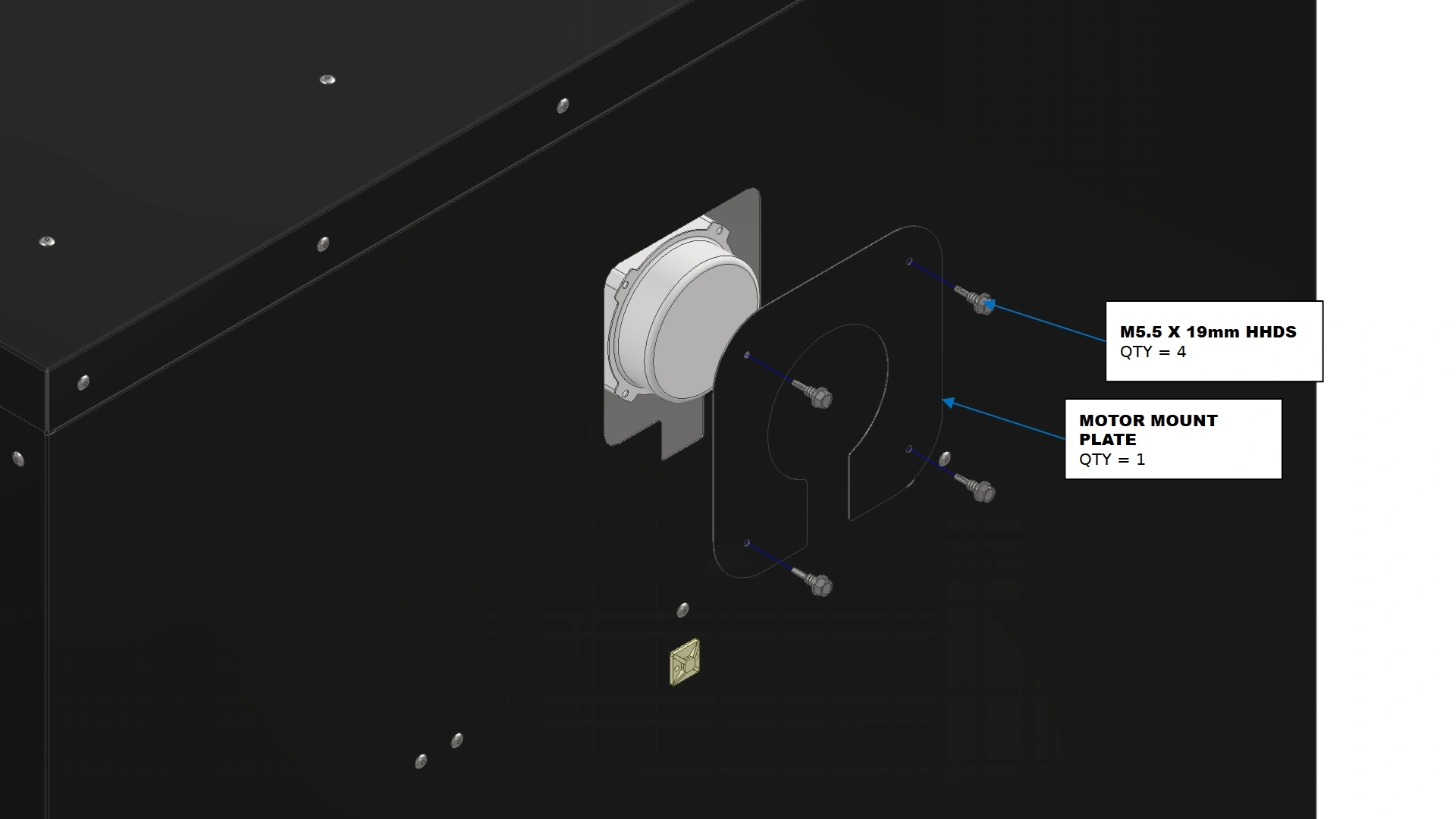
Instructions
- Transition back to the outside of the rear wall.
- Locate the Motor Mount Plate that came with your kit.
- Using the fasteners provided with your main Vulcan 16 unit for the cover plates, install the motor mount plate to cover the exposed insulation where the motor now sits.
5: Routing the Wires
The next step is to route the wiring.
Materials
Parts
- (1) Electronics Enclosure
- (1) Motor (installed)
- (1) Motor Capacitor (Optional)
Hardware
- (3) Adhesive Backed Cable Mounts
- (3) Zip Ties
Tools
- (optional) microfiber cloth/towel
- (optional) Isopropyl Alcohol/degreaser
Instructions
- Locate the wiring harness on the back of the motor.
- Connect the terminated end of the harness to the electronics box port that reads “Motor”
- Using the adhesive backed cable mounts from the main unit, secure the harness along the side of the unit.
- The spade terminals on the harness can be input into the female spades on the motor capacitor or this step can be done after step 6.
Materials
Parts
- N/A
Hardware
- (2) Stainless Steel P-Clips
- (2) M5.5 x 19mm HHDS
Tools
- 8mm socket
- Drill or Impact Driver
Instructions
- Locate the two holes highlighted in the above image.
- Using the existing P-clips from the main unit and the two additional P-clips provided in this kit, route the wiring of the heat element and thermocouples such that the fan blade will not hit them during operation as shown.
6: Upgrading the Electronics Box
The final step is to update the electronics enclosure.
Materials
Parts
- (1) Electronics Enclosure
- (3) Thin interface relays
Hardware
- N/A
Tools
- 3mm Hex Key
Instructions
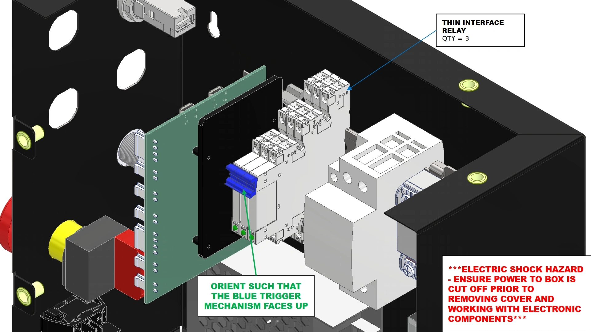
ELECTRICAL SHOCK
All power to the electronics enclosure must be removed prior to working inside. Ensure the power cable has been removed from the wall outlet before continuing.
- Locate the Vulcan 16 Electronics Enclosure and remove the front panel with the 3 mm hex key.
- Locate the 3 thin interface relays that came with your Fan kit.
- Install the thin relays onto the DIN Rail as shown with the blue plastic trigger piece facing up as shown.
Materials
Parts
- (1) PCO-HARNESS-202
Hardware
- N/A
Tools
- ⅛” Flat Head Screwdriver
- #2 Phillips Drive Screwdriver
- 2.5mm Hex Key
Instructions
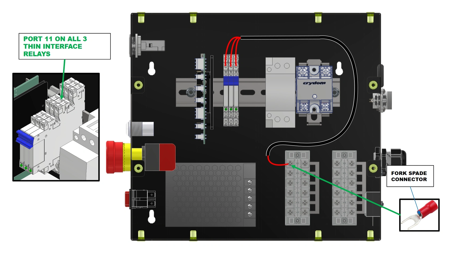
- Locate PCO-HARNESS-202 that came with your kit.
- Identify the three terminal blocks at the bottom of the enclosure.
- Remove the plastic covers from the terminal block closest to the power supply and the terminal block located on the sidewall of the enclosure.
- Identify the three ports on the thin relays labeled “11” for wire installation.
- Using the provided diagram, route wiring harness PCO-HARNESS-202 as shown.
Note
PCO-HARNESS-202 provides power to the relays. There is no defined order for the pin connectors.
Materials
Parts
- (1) PCO-HARNESS-203
Hardware
- N/A
Tools
- ⅛” Flat Head Screwdriver
- #2 Phillips Drive Screwdriver
Instructions
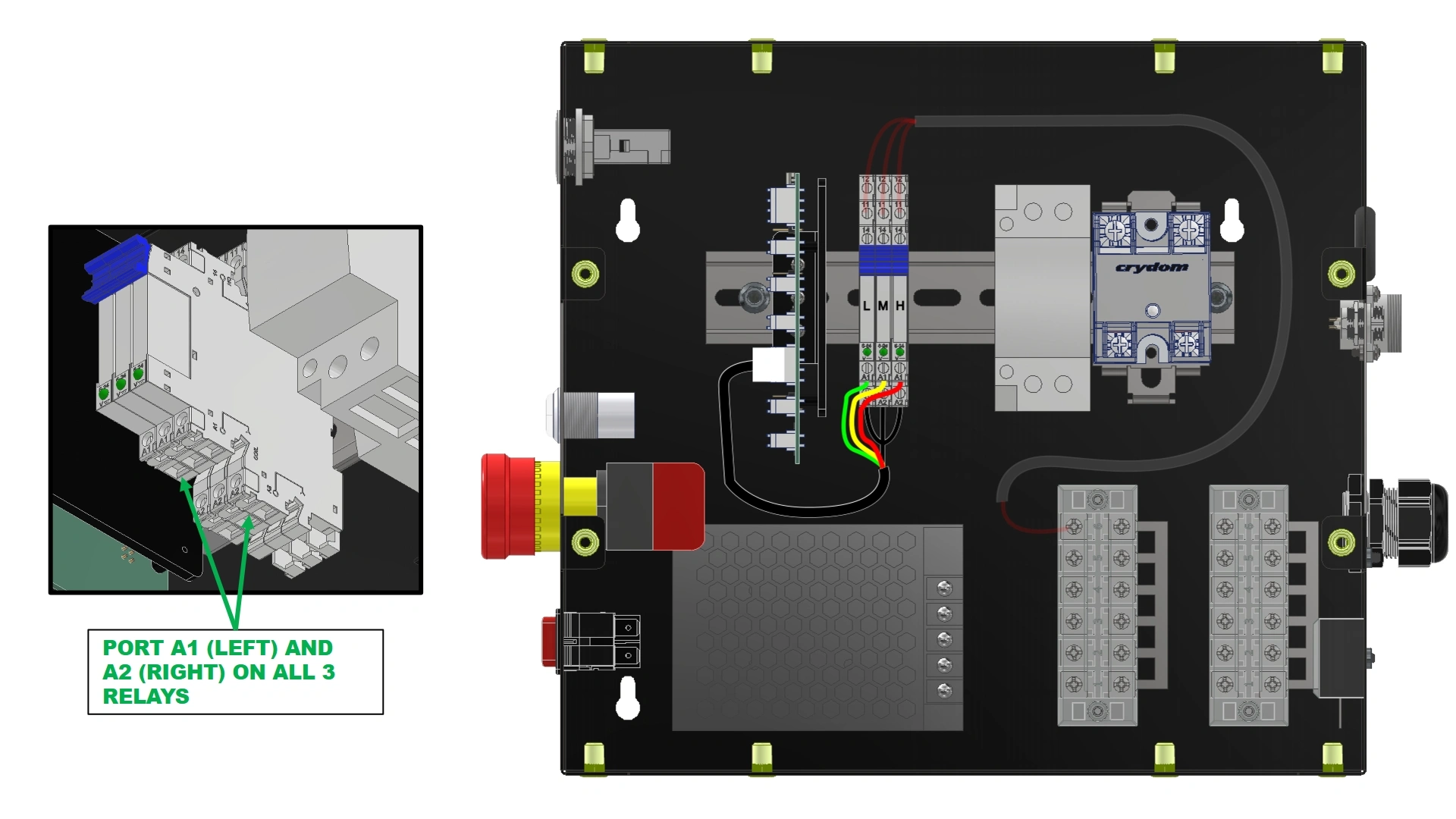
- Locate PCO-HARNESS-203 that came with your kit
- Identify Ports A1 and A2 on each of the 3 thin relays mounted to the DIN Rail.
- The A1 ports will be used for determining motor speed while A2 will connect to ground. The A2 ports do not have a designated order of installation.
NoteNotice in the image that the relays are labeled “L” for Low, “M” for Medium, and “H” for High based on the corresponding available motor speeds. This diagram increases speed from left to right for clarity. If you switch the corresponding wire colors, your relays will be in a different speed order than the provided diagram.
- Using the provided diagram, route the wiring harness as shown.
Materials
Parts
- (1) PCO-HARNESS-201
Hardware
- N/A
Tools
- ⅛” Flat Head Screwdriver
- #2 Phillips Drive Screwdriver
- Adjustable wrench
- 2.5mm Hex Key
Instructions
- Locate PCO-HARNESS-201 that came with your kit
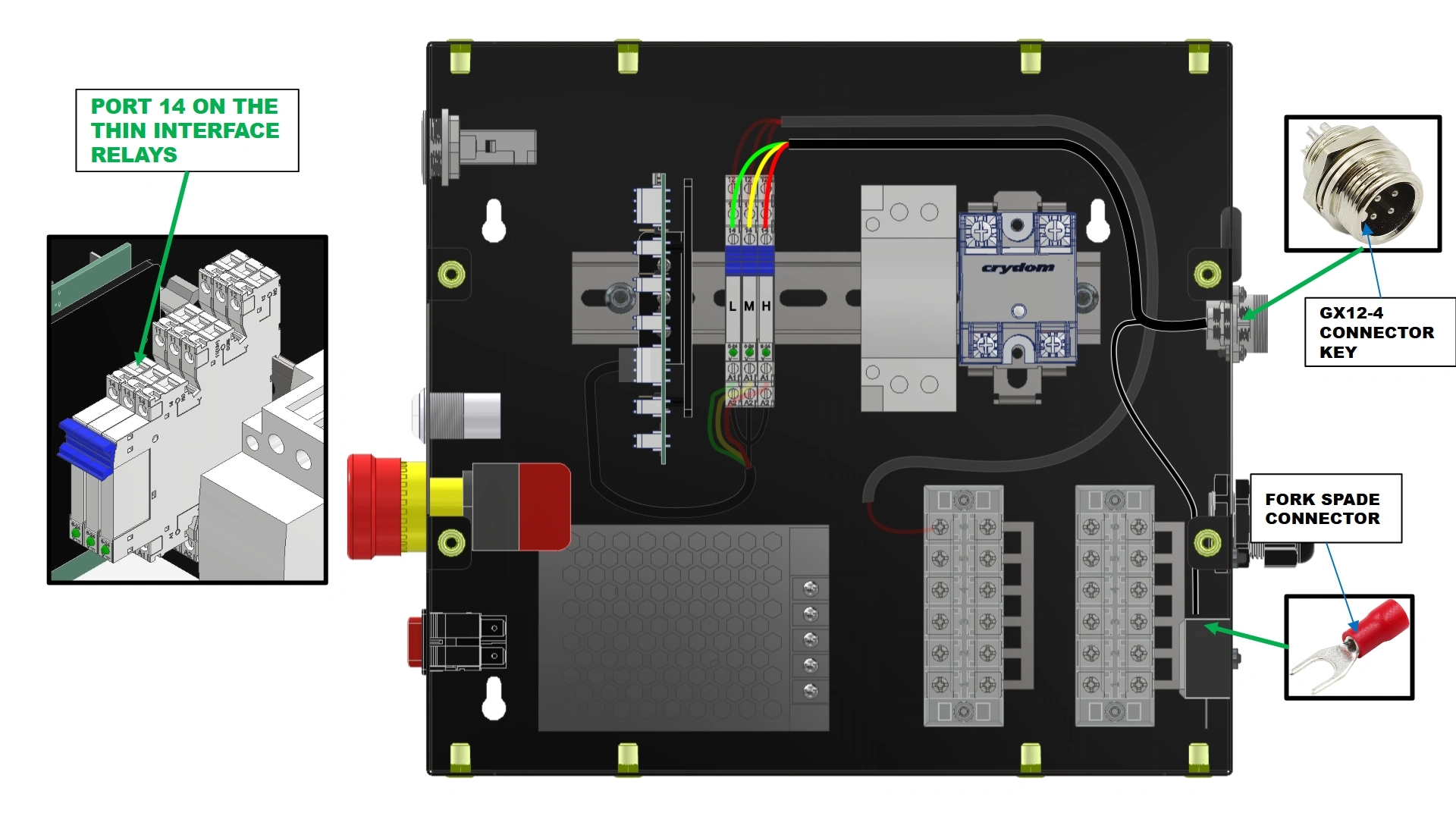
- Identify the ports labeled “14” on the top of the thin relays.
Color MatchingThe wire colors for each relay must match the wire color routed to the A1 port from the previous step.
- Remove the plastic plug sitting in the motor port of your enclosure
- Using the GX12-4 Connector end, secure the harness to the electronics enclosure with the key oriented to the top. Use the panel nut attached to the connector to secure the harness. Tighten with an adjustable wrench.
- Using the provided diagram, route the wiring harnesses as shown.
- Reinstall the plastic covers of the terminal blocks.
- Re-install the front cover of the electronics enclosure.
Materials
Parts
- (1) Capacitor Mount Bracket
- (1) Motor Capacitor
Hardware
- (1) M5 x 0.8 x 10mm BHCS (Pre-installed)
Tools
- 3mm Hex Key

Instructions
- Locate the Capacitor Mount Bracket and Motor Capacitor provided in your kit.
- Using the existing screw located at the back of the electronics enclosure on the bottom surface, install the capacitor mount bracket as shown.
- Place the capacitor that came in your kit into the bracket.
- If you have not done so already, attach the spade terminals on the motor harness to the capacitor terminals. The wire leads are not specific to one another.
- This completes the installation of the Motor & Fan Kit Add-on.
Vulcan Light Kit Add-on
Images in this Guide
The assembly drawings and pictures included in this guide can be expanded to
full-screen and zoomed to provide more detail on a given step.
1: Preparing for Installation
The first step to installing the light kit is to prepare the ceiling assembly.
Materials
Parts
- (1) Ceiling Assembly (Uninstalled)
Hardware
- N/A
Tools
- Knife
- Wire Snips
Instructions
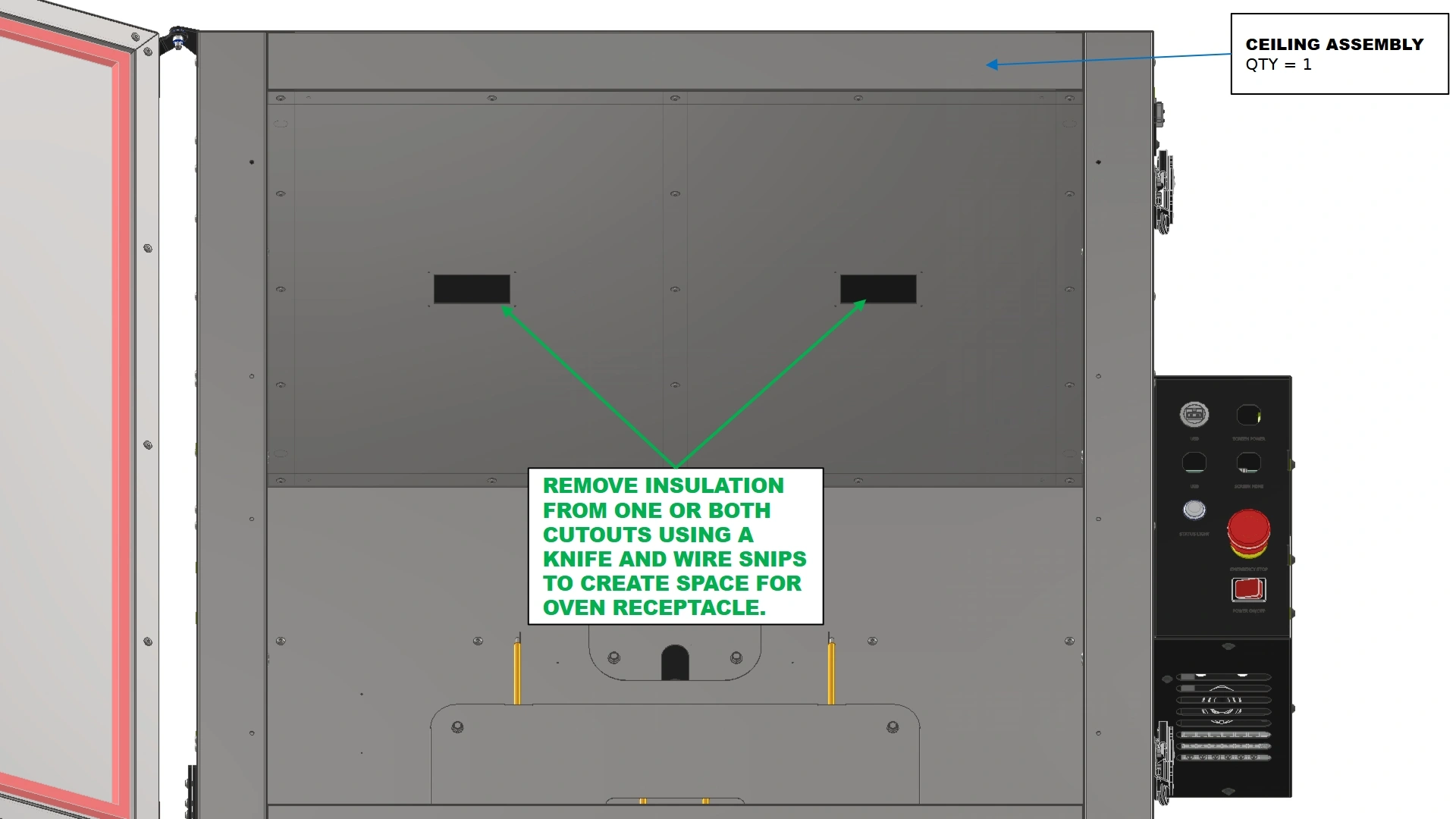
- Locate the Ceiling Assembly of your unit.
- Using a knife and wire snips, remove the insulation from the light socket cutout you plan to use such that when the light is installed, insulation will not interfere with the receptacle
2: Routing the Wires
The next step in the assembly process is to route the wire harnesses through the ceiling.
Materials
Parts
- (1) Ceiling Assembly
- (1) Oven Light Receptacle
Hardware
- N/A
Tools
- Fixturing Wire/Coat Hanger
- (Optional) Tape
Instructions
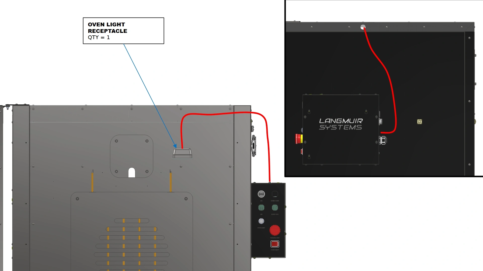
- Locate the Oven Light Receptacle that came with your kit.
- Locate a guiding wire/rod. A thicker gauge wire is recommended for ease of installation.
NoteThe span of travel for the light harness is quite long and will require a stiffer guide material. A heavy-duty wire gauge similar to a wire coat hanger should be the minimum for success.NoteEnsure you have a guide rod/wire of ample length prior to routing the wiring.
- Using fixturing wire, a coat hanger, or equivalent, feed your guide through the light cut outs in the ceiling towards the side with the electronics box. If done correctly, the end of your guide will extend out of the top of the oven assembly in a similar path to the red example route shown.
- Using electrical tape or by bending the fixturing wire, secure the GX terminated end of the oven light wire harness to the wire guide and pull the length through the ceiling assembly until the cable is routed through the oven
![]() INSULATIONDo not rush routing cables. Failure to use diligence in this process can result in damage to the wiring harness and excessive removal of insulation. If you feel excessive resistance on the cable while routing, stop pulling, back the guide wire out, and try again. In some cases, it may be necessary to use a long screwdriver or rod to create a tunnel in the insulation for easier passage.
INSULATIONDo not rush routing cables. Failure to use diligence in this process can result in damage to the wiring harness and excessive removal of insulation. If you feel excessive resistance on the cable while routing, stop pulling, back the guide wire out, and try again. In some cases, it may be necessary to use a long screwdriver or rod to create a tunnel in the insulation for easier passage.![]() NoteDo NOT install the receptacle into the ceiling at this point.
NoteDo NOT install the receptacle into the ceiling at this point. - Do NOT install the receptacle into the ceiling at this point.
- If you are finished installing the lights, push the receptacle into the cutout of the ceiling until it fully seats.

3: Wiring
The final step in the assembly process is to wire up the light in the electrical enclosure.
Materials
Parts
- (1) Electronics Enclosure Assembly
- (1) Thin Interface relay
- (1) Control board wire harness (PCO-HARNESS-304)
- (1) Relay wire harness (PCO-HARNESS-303)
- (1) Panel Mount wire harness (PCO-HARNESS-302)
Hardware
- (12) M5 x 0.8mm x 10mm BHCS
Tools
- 3mm Flathead Screwdriver
- Phillips Head #2 Screwdriver
- 3mm Hex Key
Instructions
ELECTRICAL SHOCK
All power to the electronics enclosure must be removed prior to working inside. Ensure the power cable has been removed from the wall outlet before working on the electronics box.
- Locate each unique wire harness and Thin Interface Relay that came with your Vulcan light kit.
- Locate the Electronics Enclosure Assembly that came with your Vulcan 16 unit.
- Remove the front cover from the electronics assembly and set aside for later.
Materials
Parts
- (1) Electronics Enclosure Assembly
- (1) Thin Interface relay
- (1) Control board wire harness (PCO-HARNESS-304)
- (1) Relay wire harness (PCO-HARNESS-303)
- (1) Panel Mount wire harness (PCO-HARNESS-302)
Hardware
- N/A
Tools
- ⅛” Flat Head Screwdriver
- Adjustable Wrench
- #2 Phillips Drive Screwdriver
Instructions
ELECTRICAL SHOCK
All power to the electronics enclosure must be removed prior to working inside. Ensure the power cable has been removed from the power receptacle located on the back of the box.
- Using the DIN rail mounting geometry on the thin interface relay, Install both thin interface relays onto the DIN Rail in the same orientation as shown with the blue trigger facing up.
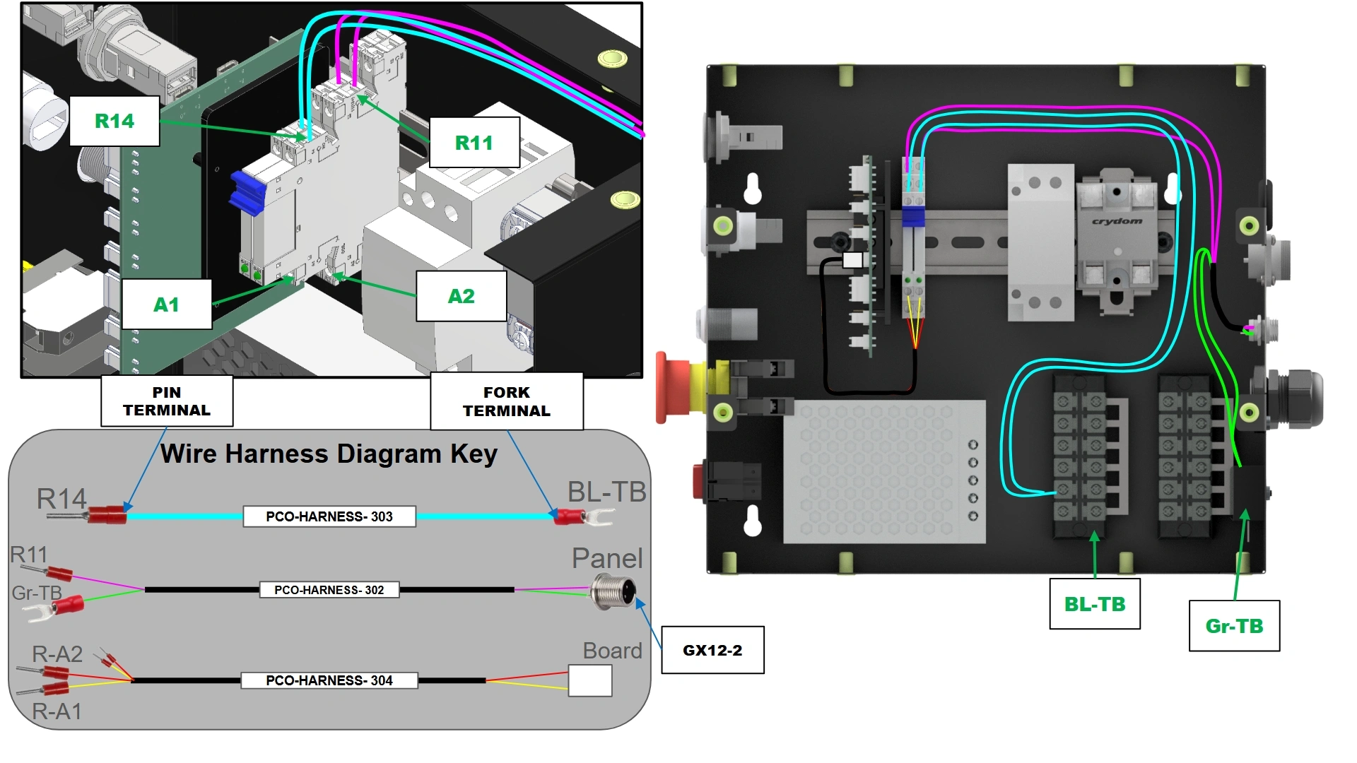
- Locate wire harness “PCO-HARNESS-304” and install the Panel Mount ends into the cutouts labeled “Light 1” and “Light 2” on the back of the enclosure. Secure the connector with the provided nut and an adjustable wrench.
- Each “PCO-HARNESS-302” will be routed to a thin interface relay. Locate the “PCO-HARNESS-302” in the “Light 1” cut out of the box. Route the Black wire of the harness with the pin termination to the thin interface relay closest to the control board. Input the Pin into R11 port of the relay. Route the red lead with fork termination of the “PCO-HARNESS-302” into the terminal block directly below the port cut out.
- With the remaining provided “PCO-HARNESS-302”, route the harness to the remaining thin interface using the same wiring instructions from step B3.
- Locate both “PCO-HARNESS-303”. Wire the fork terminated ends of the wires into the left-most terminal block of the enclosure. Wire the remaining pin terminated ends of the wires into the “R14” Ports of the thin interface relays.
- Locate the remaining “PCO-HARNESS-304”. Plug the white JST connector into the control board on the port labeled “light”. On the pin terminated end of the harness, route one pair of black and red wires to the thin interface relay closest to the control board. Insert the red wire into port “A1” on the relay and the black wire into port “A2”. Repeat this wiring for the remaining pair of black and red pinned wires.
Materials
Parts
- (1) Electronics Enclosure Assembly
Hardware
- (12) M5 x 0.8mm x 10mm BHCS
Tools
- 3mm Flathead Screwdriver
Instructions
- Locate the hardware and front panel of the Electronics Enclosure Assembly removed in step A3.
- Reinstall the front panel with the 3mm hex key.
- Once installed, you may plug in the bulb wire harness into the back of the electronics enclosure, or proceed with assembly and connect the light at a later time.
- Return to the Vulcan 16 Assembly guide to finish assembling your unit if you have not done so already.
Vulcan 16 Fixture Kit
Images in this Guide
The assembly drawings and pictures included in this guide can be expanded to
full-screen and zoomed to provide more detail on a given step.
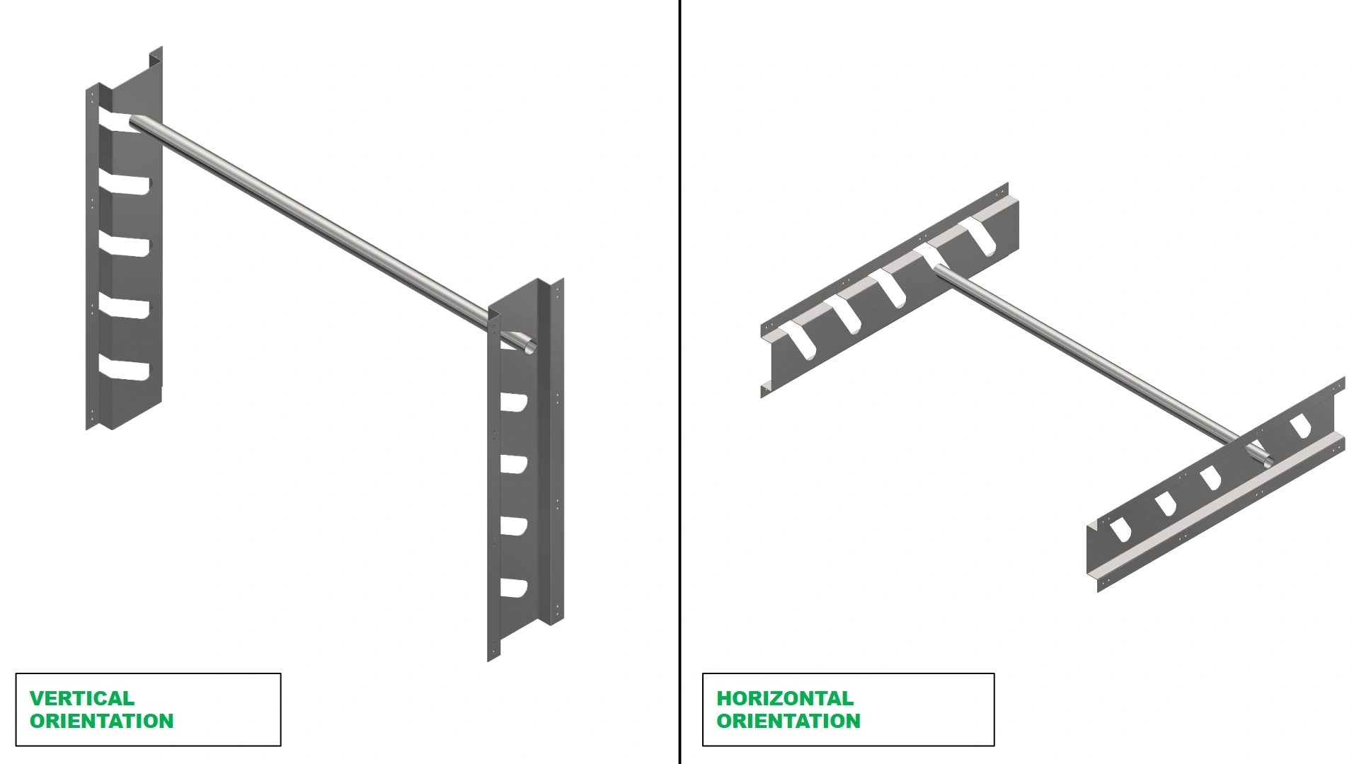
1: Deciding Orientation
The first step in the assembly of the fixture kit is to determine its orientation.
Materials
Parts
- (2) Fixturing Plates
- (1) Fixture Bar
Hardware
- N/A
Tools
- N/A
Instructions
- Depending on your use case, the orientation of your Fixture Bar Kit will matter significantly. Use this time to determine if you would like to have access to varying heights of your oven, or varying depths.
Note
While the Fixture Bar Kit is limited to a single orientation, they can be switched at any time. For simultaneous access to depth AND height adjustment, we provide the Variable Mesh Fixture Kit available on our store that pairs with the vertical installation of the Fixture Bar Kit.
2: Preparing the Vulcan
The next step in the assembly process is to prepare the mounting hole locations
Materials
Parts
- (1) Vulcan 16
Hardware
- N/A
Tools
- 4mm or 5/32 Carbide Drill bit
- Cutting Oil
- Drill
- Rubbing Alcohol
Instructions
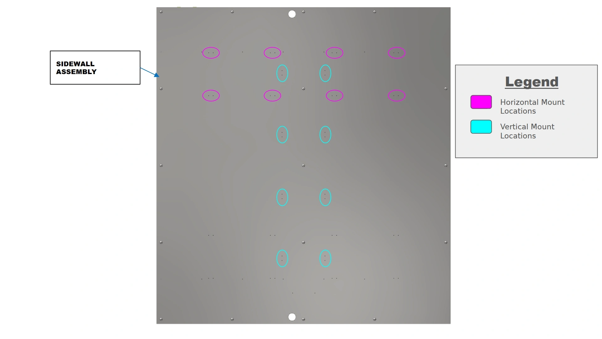
- Once you have selected the orientation best suited for your needs, look inside your oven and locate the provided pilot hole locations on your sidewalls. Use the provided image as a reference to easily locate the pilot holes.
- The provided pilot holes are approximately 1mm in diameter. They will need to be bored out further for ease of installation.
![]() PERSONAL PROTECTIVE EQUIPMENTCarbide drill bits are extremely susceptible to fracture and can eject sharp carbide during drilling. It is imperative to wear safety glasses during this process to avoid serious injury.
PERSONAL PROTECTIVE EQUIPMENTCarbide drill bits are extremely susceptible to fracture and can eject sharp carbide during drilling. It is imperative to wear safety glasses during this process to avoid serious injury.![]() NoteStainless steel is extremely resistant to drilling operations, making this a time intensive process. The use of cutting oil during drilling will prevent work hardening due to heat generated by friction. If you are new to carbide drill bits, go slowly and obtain a feel for the cut to ensure the longevity of your bit.NoteThe plates are not symmetrical while the sidewall assemblies are. Two hole locations have been provided to ensure proper alignment during installation. During drilling, ensure you use the same holes on both sidewalls to avoid misalignment of the plates. As an example, if mounting in the horizontal position on the left-hand wall AND using the leftmost pilot holes (closest to the door), when mounting to the right-hand wall, you would use the rightmost holes (closest to the door) to properly mirror the locations.
NoteStainless steel is extremely resistant to drilling operations, making this a time intensive process. The use of cutting oil during drilling will prevent work hardening due to heat generated by friction. If you are new to carbide drill bits, go slowly and obtain a feel for the cut to ensure the longevity of your bit.NoteThe plates are not symmetrical while the sidewall assemblies are. Two hole locations have been provided to ensure proper alignment during installation. During drilling, ensure you use the same holes on both sidewalls to avoid misalignment of the plates. As an example, if mounting in the horizontal position on the left-hand wall AND using the leftmost pilot holes (closest to the door), when mounting to the right-hand wall, you would use the rightmost holes (closest to the door) to properly mirror the locations. - With a carbide drill bit and cutting oil, work your way around to each mounting hole location and increase the diameter of the hole until it is slightly undersized to the provided M5.5 fasteners provided in your kit.
- Use rubbing Alcohol to remove residual cutting oil from the walls surface.
NoteFailure to wipe oil off the surface before running the oven can be a significant fire hazard. Ensure your surface is clean and ready for operation before turning on the heat element.

3: Installing the Fixture
The final step in the assembly is to install the fixturing.
Materials
Parts
- (1) Fixture Plate
- (1) Mirrored Fixture Plate
Hardware
- (16) M5.5 x 19mm HHDS
Tools
- 8mm Socket
- Socket Driver
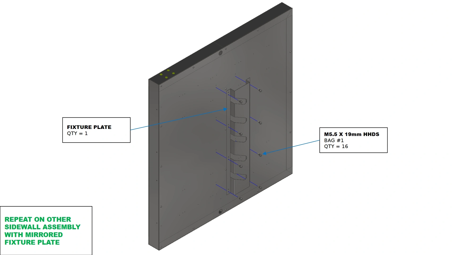
Instructions
- Locate both Fixture Plates that came with your kit.
- Orient the the slots of the plates such that the opening is closest to you, the user, as shown.
- Using the fasteners shown, install the plates using the bored out holes from the previous step using a 8mm socket and socket driver.
NoteIf you have an adjustable torque setting on your socket driver, ensure it is not set to the drill mode as this can cause the mounting holes to be loose around the HHDS used to secure the plates. We recommend a torque setting of 12 on your standard socket driver.
- Repeat steps A1-A3 for the remaining plate on the opposite side wall.
Materials
Parts
- (1) Fixture Bar
Hardware
- N/A
Tools
- N/A
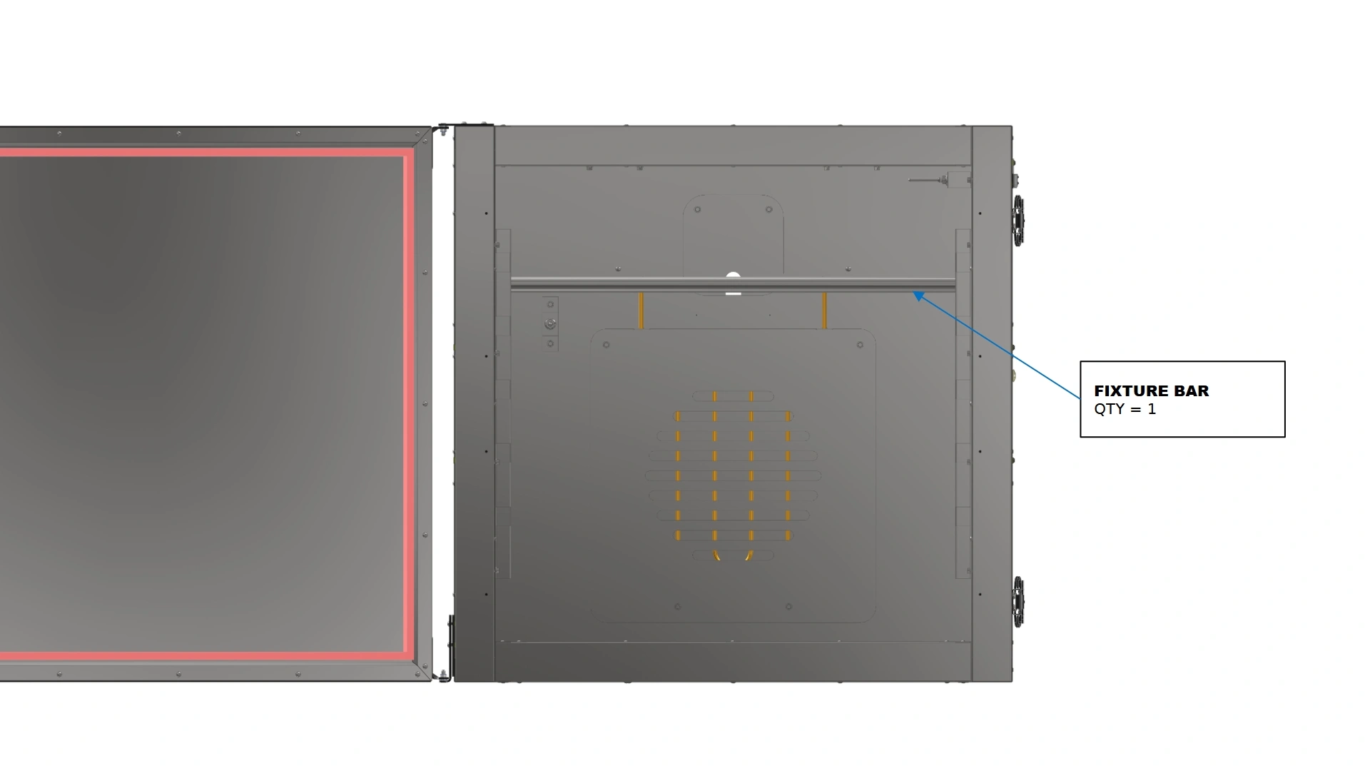
Instructions
- Once both plates are installed, you may position the included fixture bar in whichever position you prefer to ensure proper alignment.
- Your fixture bar should be level with your oven if aligned properly.
Note
Additional Fixture Bars are available via the Langmuir Systems store
Vulcan 16 Leg Kit Assembly Guide
Images in this Guide
The assembly drawings and pictures included in this guide can be expanded to
full-screen and zoomed to provide more detail on a given step.
1: Installing the Feet
The first step in the assembly process is to install the leveling feet
Materials
Parts
- (4) Machine Leg
- (4) Leveling Foot Mount
- (4) Swivel Leveling Foot, ⅜-16 Stem
Hardware
- (4) ⅜-16 Jam Nut (Pre-installed on leveling foot stem)
- (8) 5/16-18 Button Head Cap Screw
Tools
- 3/16” Hex Key
- 9/16” Wrench
- 14mm Wrench
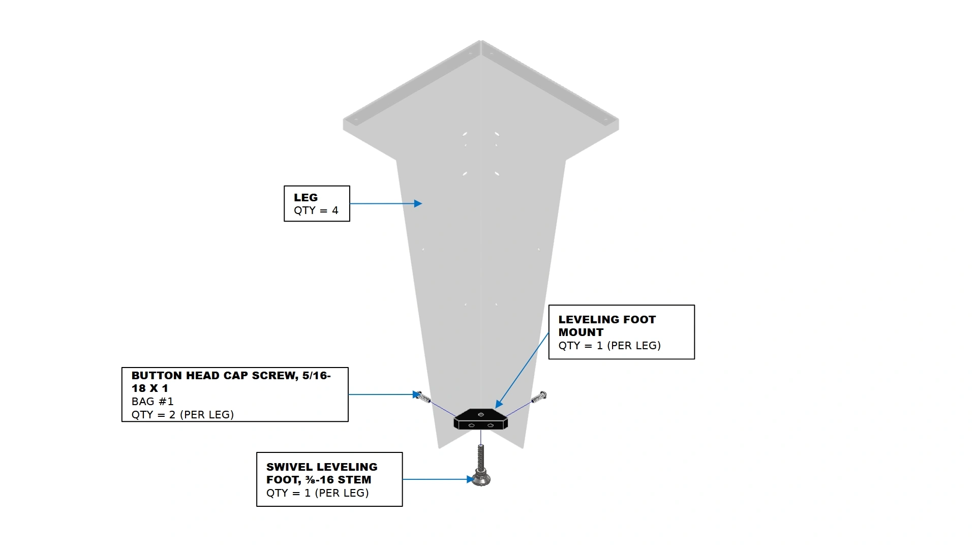
Instructions
- Locate the Machine Legs included in your kit.
- Remove the pre-installed jam nut from the leveling foot and set aside.
- Screw the leveling foot into the leveling foot mount as far as the threads will allow
- Attach the leveling foot mount to the leg using the fasteners shown.
- Reinstall the jam nut, but do not tighten.
Materials
Parts
- (4) Machine Leg
- (4) Leveling Foot Mount
- (4) Swivel Leveling Foot, ⅜-16 Stem
Hardware
- (4) ⅜-16 Jam Nut
- (8) 5/16-18 Button Head Cap Screw
Tools
- 3/16” Hex Key
- 9/16” Wrench
- 14mm Wrench
Instructions
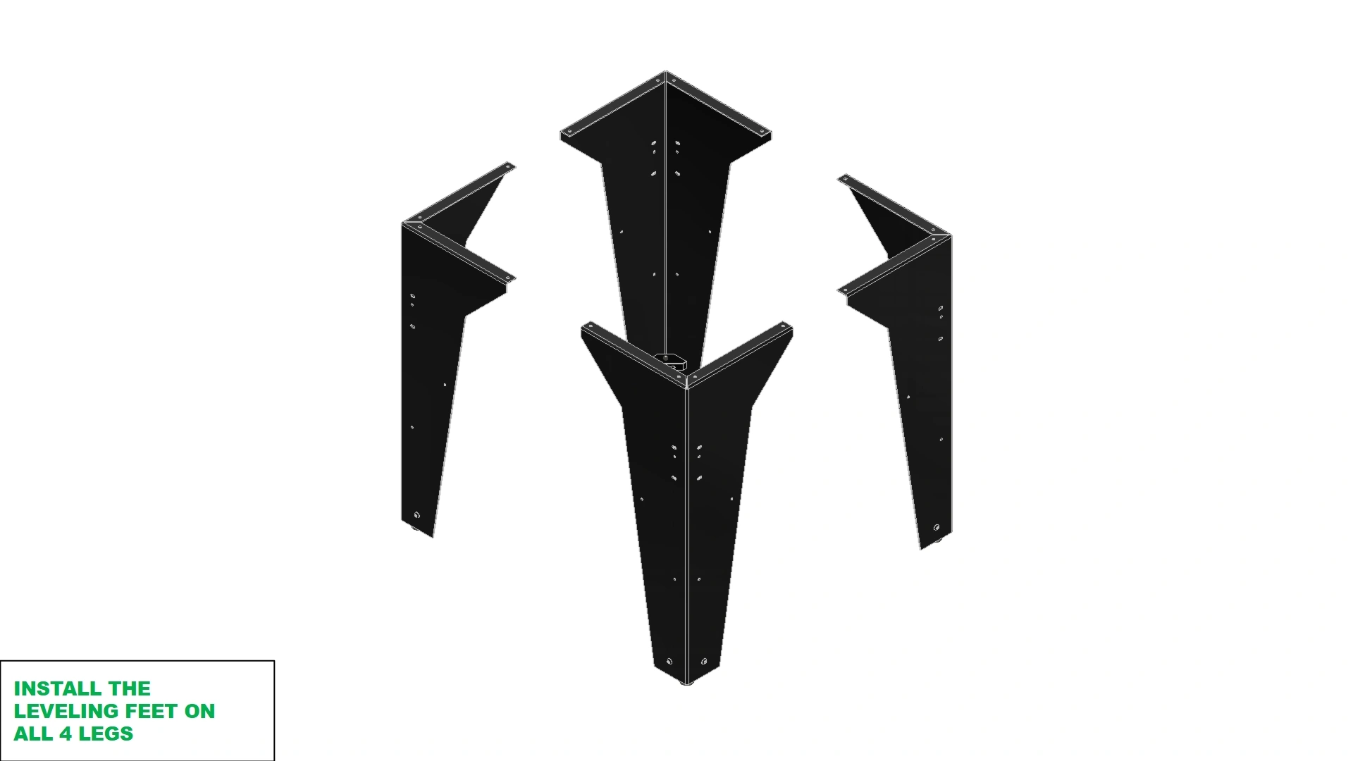
- Repeat steps A2-A5 on the remaining three legs.
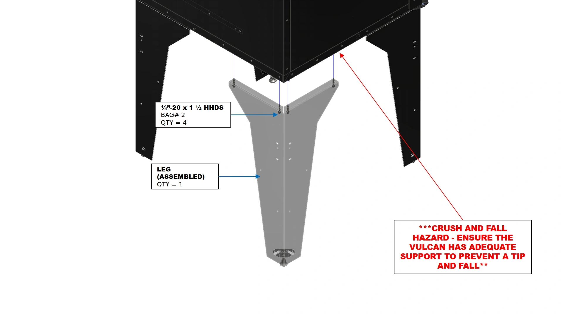
2: Installing the Legs
The next in the assembly process is to install the legs onto the unit.
Materials
Parts
- (1) Assembled Vulcan 16
Hardware
- N/A
Tools
- Vertical Support
Instructions
Note
The leg kit can be installed with the Vulcan positioned resting on the
rear wall to access the floor assembly. Once all legs are installed, use at least 2
people to pick up and orient the Vulcan into the upright position. To prevent
scratching, it is recommended to use a soft surface under the Vulcan for this
method.
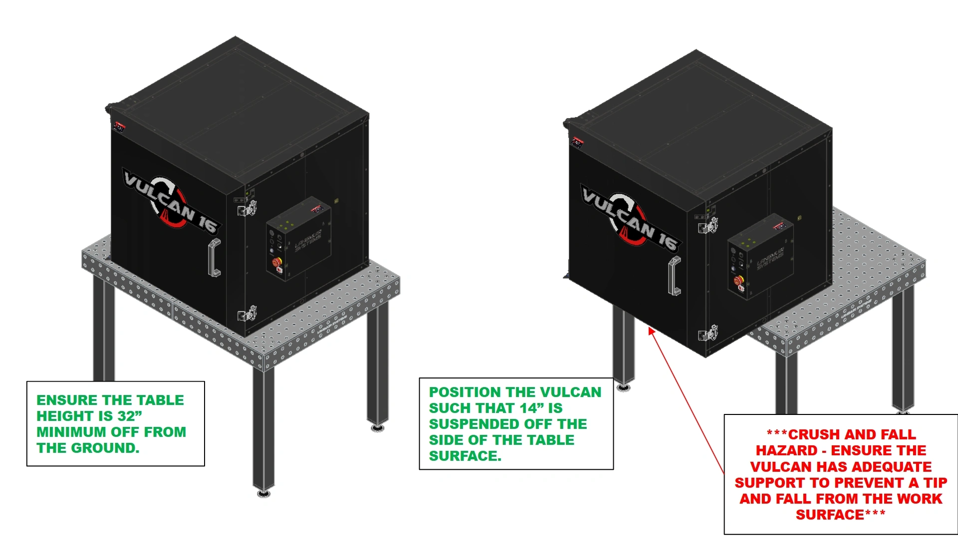
- With the Vulcan 16 positioned on a benchtop, ensure the bottom surface of the oven is at least 32 inches off the ground.
NoteIf your work surface is elevated much higher than the height of the legs, you can use scrap wood to elevate the legs for easier attachment. It is recommended that an additional person hold the position of the leg while the other secures them in place.
- Push the Vulcan 16 until 14 inches of the bottom surface is positioned off of one side of the table.
![]() CRUSH HAZARD & FALL HAZARDPushing the vulcan too far off the table can cause the unit to topple forward presenting a significant crush hazard. Falling from a 32” height may also damage the unit. It is strongly recommended to position a vertical support under the portion of the Vulcan hanging off the table that is out of your way during installation of the legs.
CRUSH HAZARD & FALL HAZARDPushing the vulcan too far off the table can cause the unit to topple forward presenting a significant crush hazard. Falling from a 32” height may also damage the unit. It is strongly recommended to position a vertical support under the portion of the Vulcan hanging off the table that is out of your way during installation of the legs.![]()
- Using a vertical prop, support the underside of the vulcan that is suspended off the ground. Ensure the vertical prop does not obstruct installation of the legs.
Materials
Parts
- (1) Assembled Vulcan 16
- (2) Machine Legs (Assembled)
Hardware
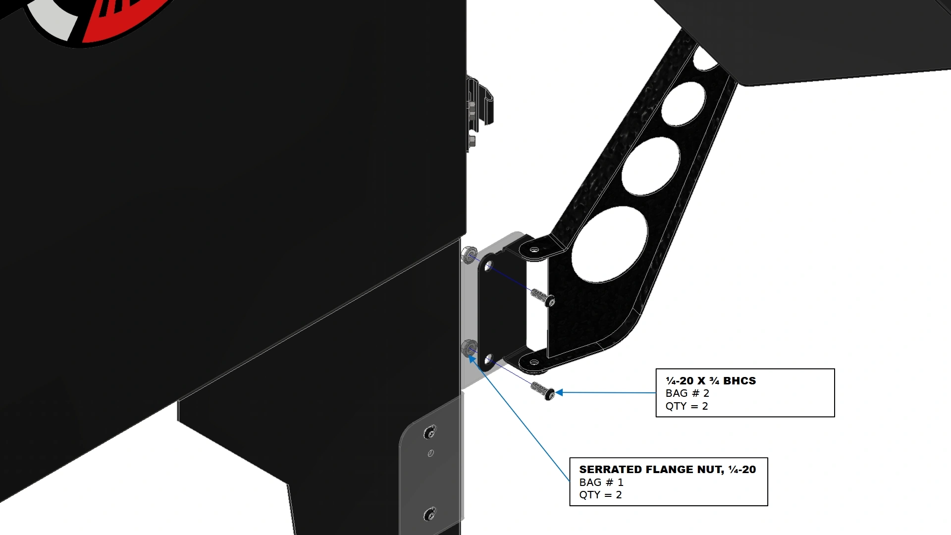
- (16) ¼”-20 x 1 ½ HHDS
Tools
- Vertical Support
- ⅜” Socket
- Impact Drill
- (Optional) Punch
Instructions
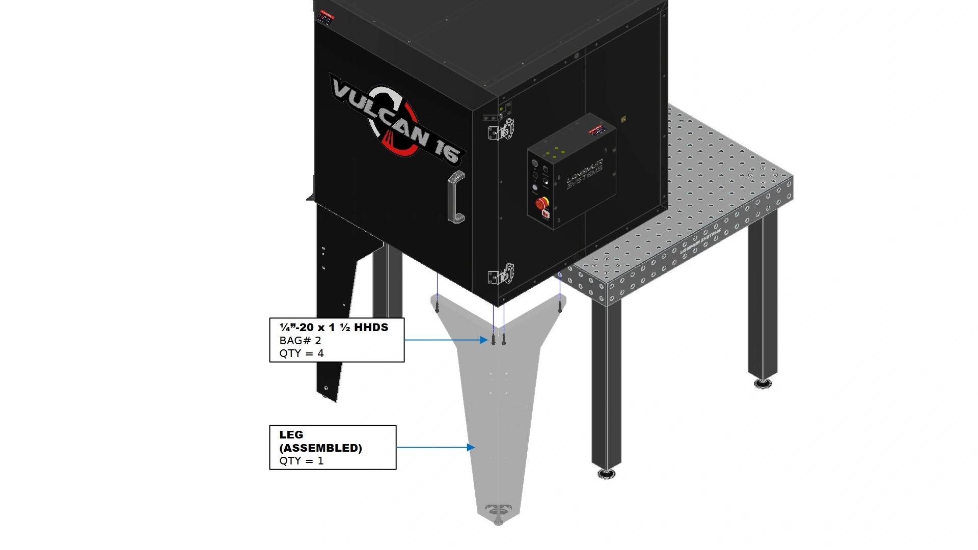
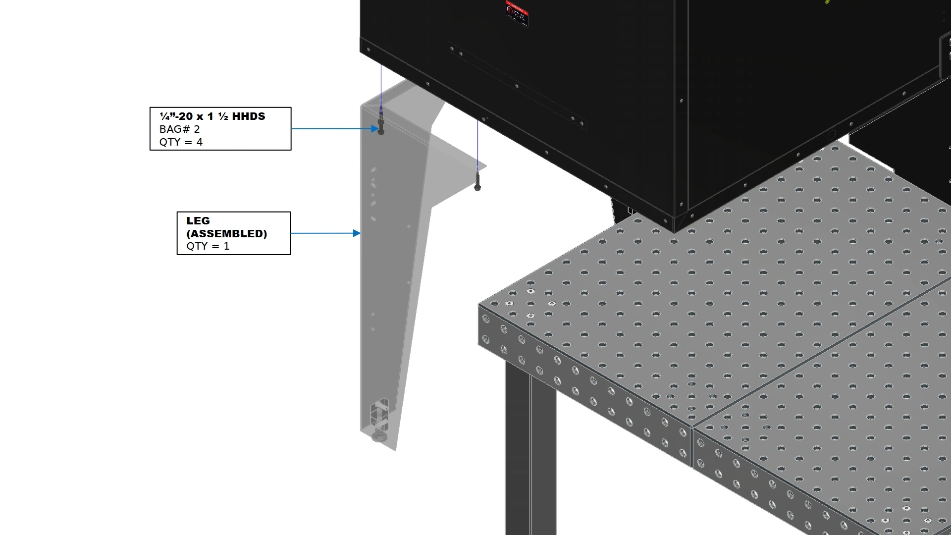
- Align the outer faces of the legs with the outer boundaries of the oven.
NoteThe front legs will align with the outer boundaries of the box NOT including the door.
- Using the holes on the top flanges of the legs, secure the front two legs in place with the fasteners shown while maintaining a flush orientation with the outer walls. You may use a punch tool to assist in proper placement of the Self-drilling fasteners.
Materials
Parts
- (1) Assembled Vulcan 16
Hardware
- N/A
Tools
- Vertical Support
Instructions
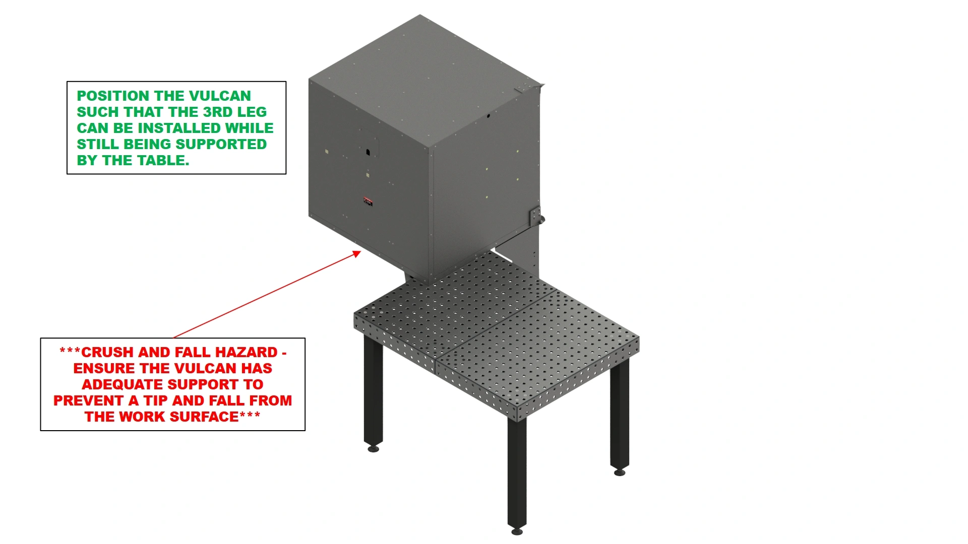
- With the 2 front legs installed, reposition the Vulcan 16 such that the 3rd leg can be installed on the back corner and the other corner is still supported by the workbench as shown.
CRUSH HAZARD & FALL HAZARD
Pushing the vulcan too far off the table can cause the unit to topple over, presenting a significant crush hazard. Falling from a 32” height may also damage the unit. It is strongly recommended to position a vertical support under the portion of the Vulcan hanging off the table that is out of your way during installation of the legs.
Materials
Parts
- (1) Assembled Vulcan 16
- (1) Machine Leg (Assembled)
Hardware
- (16) ¼”-20 x 1 ½ HHDS
Tools
- Vertical Support
- ⅜” Socket
- Impact Drill
- (Optional) Punch
Instructions
- Repeat steps B1 & B2 for the 3rd leg
Materials
Parts
- (1) Assembled Vulcan 16
- (1) Machine Leg (Assembled)
Hardware
- (16) ¼”-20 x 1 ½ HHDS
- (4) ⅜-16 Jam Nut
Tools
- 9/16” Wrench
- 14mm Wrench
- Vertical Support
- ⅜” Socket
- Impact Drill
- (Optional) Punch
Instructions
- Reposition the Vulcan so that the table is no longer supporting the weight of the unit. Do NOT attempt to balance the vulcan 16 on 3 legs. Reposition the vertical prop used in the previous steps before installing the final leg
![]() CRUSH HAZARD & FALL HAZARDSupporting the Vulcan on 3 legs will be unstable and presents a significant crush hazard. Dropping the unit may also cause significant damage. It is strongly recommended to position a vertical support under the Vulcan that is out of your way during installation of the final leg.
CRUSH HAZARD & FALL HAZARDSupporting the Vulcan on 3 legs will be unstable and presents a significant crush hazard. Dropping the unit may also cause significant damage. It is strongly recommended to position a vertical support under the Vulcan that is out of your way during installation of the final leg.![]()
- Repeat steps B1 & B2 for the 4th leg.
- Using the 9/16” and ⅝” wrench, adjust the Leveling Swivel foot until the oven sits level to the ground. Once you have achieved a good level, tighten the Jam Nut down to secure the swivel foot in place.
- The legs are now installed on your Vulcan 16 Unit and it may be moved into its designated shop area.
Vulcan 16 Computer Tray Kit
Images in this Guide
The assembly drawings and pictures included in this guide can be expanded to
full-screen and zoomed to provide more detail on a given step.
1: Assemble The Stand
The first step in the assembly process is to put the stand and tray together.
Materials
Parts
- (1) Tray
- (1) Vertical Support
- (1) Mounting Bracket
Hardware
- (4) Flathead Screw, 10-24 X 1/2
- (4) Washer, #10
- (4) Locknut, 10-24
- (2) ¼-20 X ¾ ” SHCS
- (2) ¼” Washer
- (2) ¼-20 Serrated Flange Nut
Tools
- Phillips Head Screwdriver
- ⅜” Wrench
- 7/16” Wrench
- 3/16” Hex Key
- 9/16” Wrench
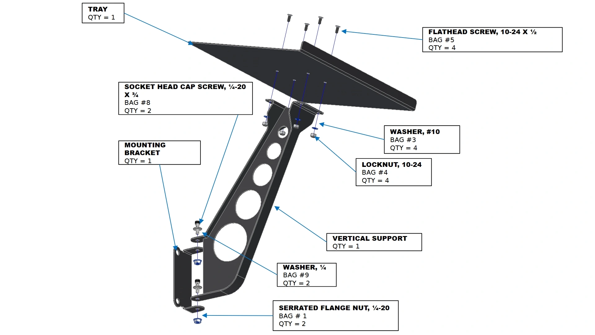
Instructions
Note
The Vulcan Computer Tray Kit is only compatible with the purchase of the Vulcan 16 Leg Kit.
- Secure the Tray to the Vertical Support using the Laptop Stand Hardware depicted.
- Secure the Vertical Support to the Mounting Bracket using the hardware depicted. The screws can be left slightly loose if swivel capability is desired.
2: Attaching the Adapter Plate
The second step in the assembly process is to attach the adapter plate to the Oven Legs.
Materials
Parts
- (1) Laptop Stand Mount Plate Adapter
Hardware
- (4) ¼”-20 x ¾” BHCS
- (4) ¼”-20 Serrated Flange Nut
Tools
- 5/32” Hex Key
Instructions
- Locate the Laptop Stand Mount Plate Adapter.
- Secure the plate in place using the holes provided on the Leg nearest to the door opening.
Materials
Parts
- N/A
Hardware
- (1) M5 x 0.8 x 15mm SHCS
- (1) M5 Serrated Flange Nut
Tools
- 4mm Hex Key
- 7/32” Drill Bit
- Drill
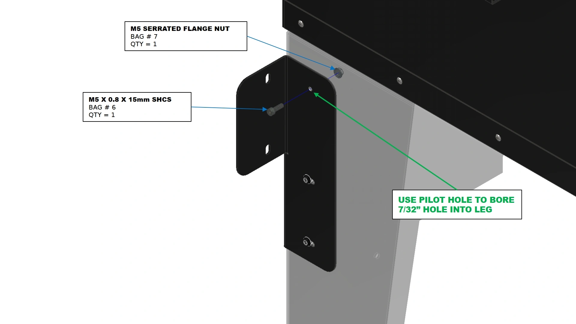
Instructions
- Using a 7/32” Drill Bit, bore a clearance hole into the leg using the small pilot hole as a guide on the adapter plate.
NoteFailure to drill and secure the top of the plate will result in a lever arm from the weight of your personal computer. It is not recommended to skip this critical step.
- Once drilled, secure the top of the plate in place using the fasteners shown.
3: Installing the Tray
The final step in the assembly process is to attach the stand to the adapter plate.
Materials
Parts
- (1) Laptop Tray Assembly
Hardware
- (2) ¼”-20 x ¾” BHCS
- (2) ¼”-20 Serrated Flange Nut
Tools
- 5/32” Hex Key
- 7/16” Wrench
Instructions
- Install the Laptop Stand Assembly onto the adapter plate with the fasteners shown.
Vulcan 16 Pro-Electronics Kit Add-on
Images in this Guide
The assembly drawings and pictures included in this guide can be expanded to
full-screen and zoomed to provide more detail on a given step.
1: Installing Panel Mounts
The First step in installing your pro-electronics kit is to install the panel mounts into the front of your enclosure.
Materials
Parts
- (1) Electronics Enclosure
Hardware
- (12) M5 x 0.8mm x 10mm BHCS
Tools
- 3mm Hex Key
Instructions
ELECTRICAL SHOCK
All power to the electronics enclosure must be removed prior to working inside. Ensure the power cable has been removed from the power receptacle in the back of the box.
- Locate the Electronics Enclosure that came with your Vulcan 16 Unit.
- Using a 3mm Hex Key, remove the 12 BHCS that secure the front cover of the box. Set the hardware and cover aside for reinstallation later.
Materials
Parts
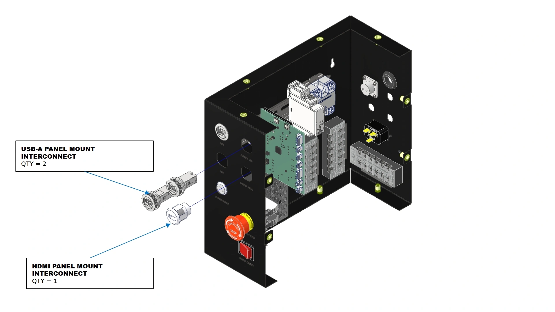
- (2) USB-A Style Panel Mount Interconnect
- (1) HDMI Panel Mount Interconnect
Hardware
- N/A
Tools
- N/A
Instructions
- Locate the 2x USB-A Panel Mount Interconnect & the HDMI Panel Mount Interconnect that came with your Pro-Electronics Kit
- Using the text identifiers on the front of your electronics enclosure, install the usb and hdmi panel mounts onto the box using the respective nuts that came with each interconnect.
2: The Onboard Computer
The next step in the installation process is to install the onboard computer that comes with your kit.
Materials
Parts
- (1) Electronics Enclosure
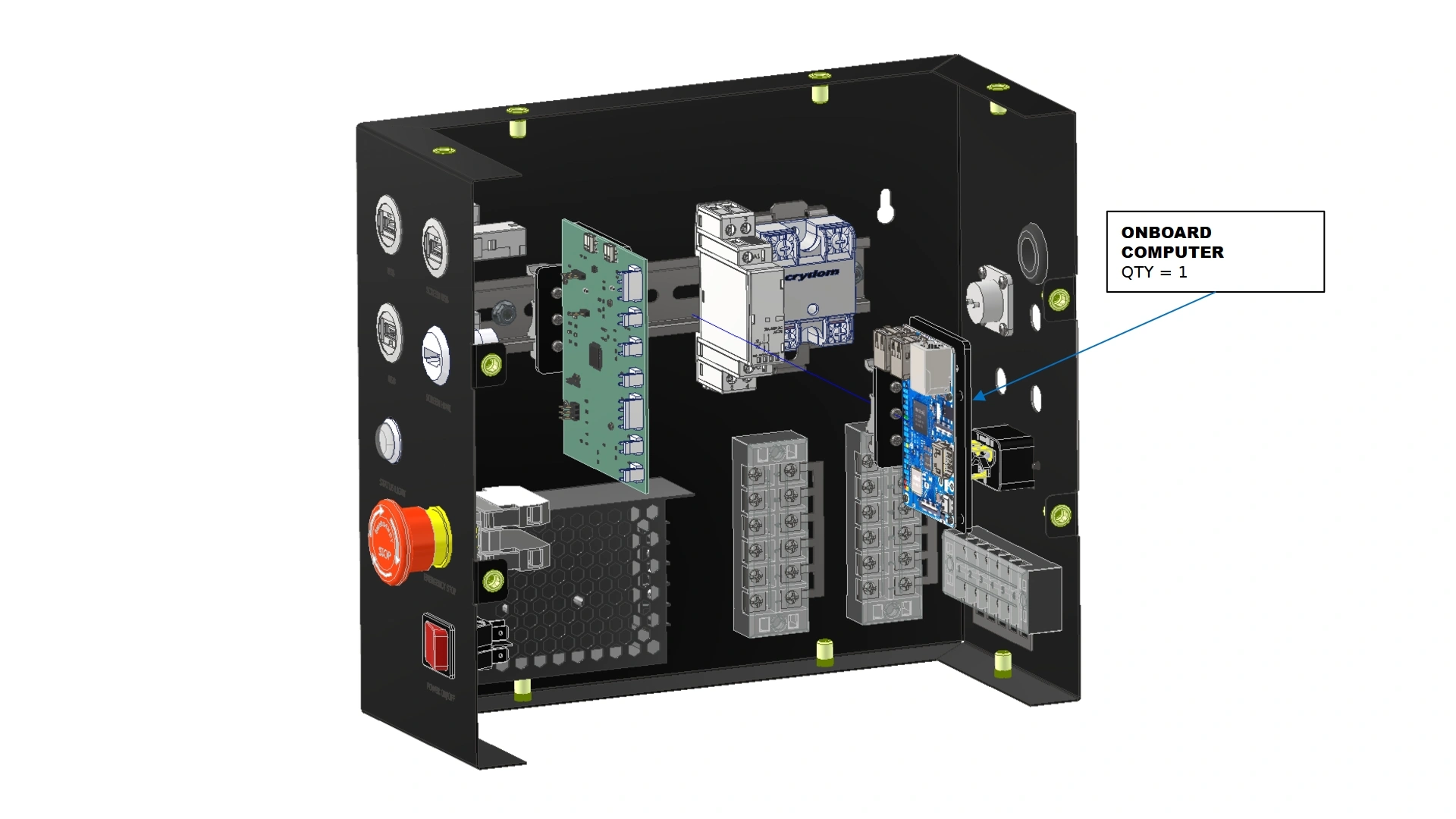
- (1) Onboard Computer
Hardware
- N/A
Tools
- N/A
Instructions
- Locate the Onboard Computer Unit that came with your Pro-Electronics Add-on Kit.
- Using the available space on the DIN Rail located inside the electronics enclosure, mount the onboard computer in the orientation shown.
3: Internal Wiring
The next step is to install the new wire harnesses that came with your add-on kit.
Materials
Parts
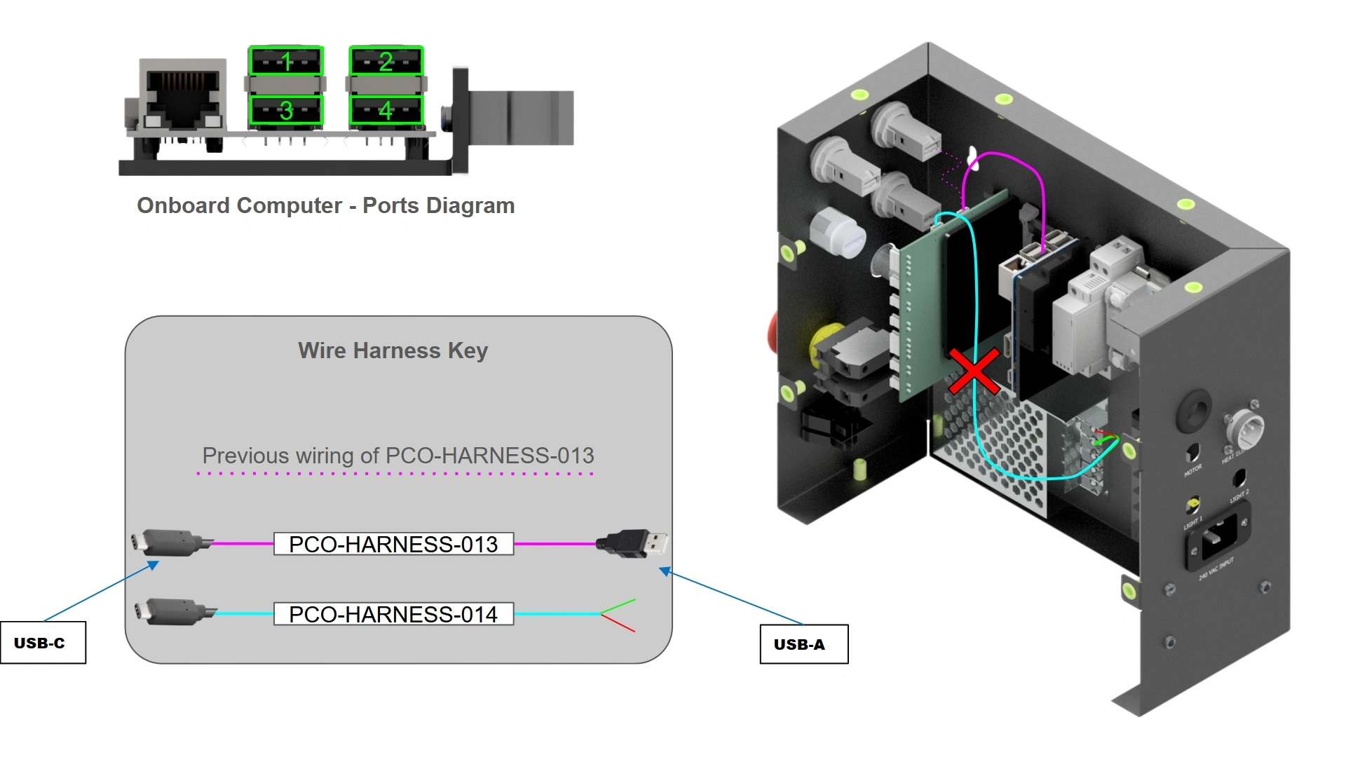
- PCO-HARNESS-013 (Factory Installed)
- PCO-HARNESS-014 (Factory Installed)
Hardware
- N/A
Tools
- #2 Phillips Head Screwdriver
Instructions
- Locate wire harness “PCO-HARNESS-013” that came pre-installed on the unit. This wire runs between the control board and the top left USB-A interconnect of your unit.
- Unplug the USB-A terminal of “PCO-HARNESS-013” from the panel mount and insert it into USB-A terminal #3 on the Onboard Computer.
- Locate wire harness “PCO-HARNESS-014” that came pre-installed on the unit. This harness runs between the Control Board and the Power Supply of the enclosure.
- Remove wire harness “PCO-HARNESS-014” from the box. This harness is now obsolete.
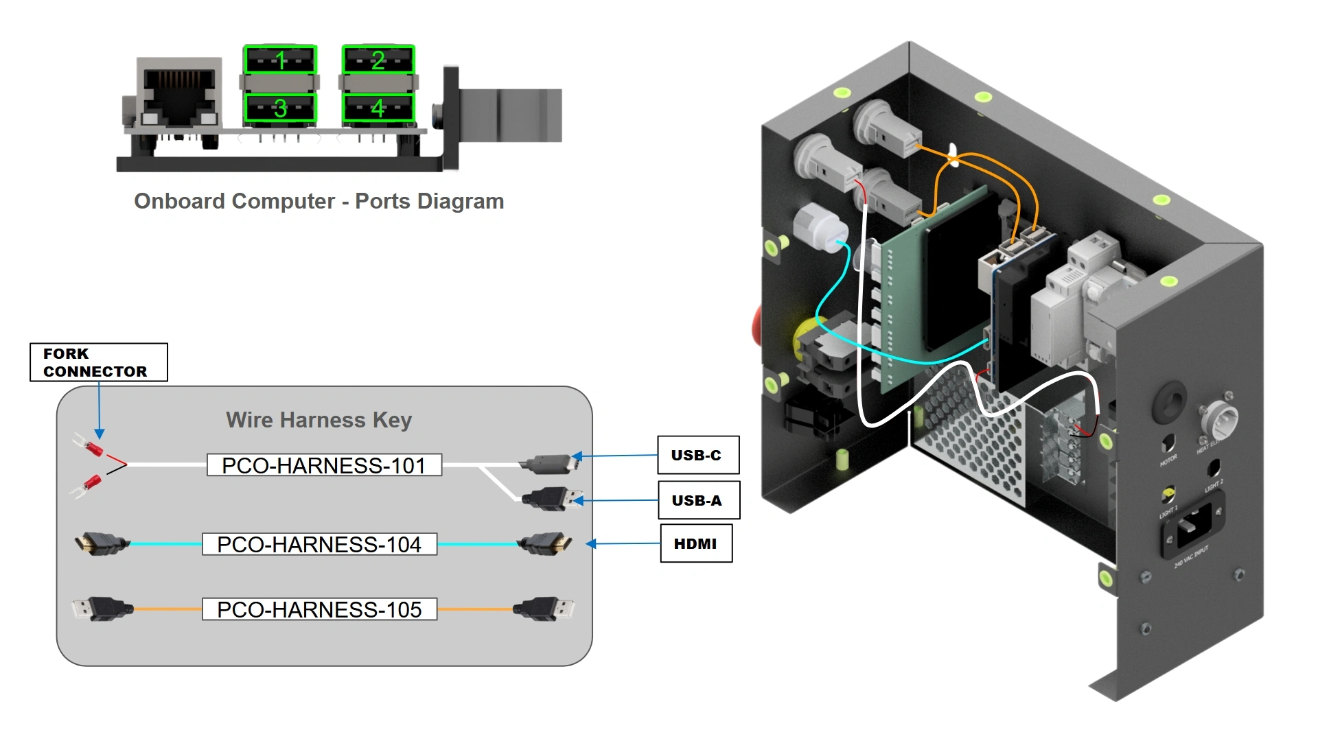
Materials
Parts
- (1) Electronics Enclosure
- (1) PCO-HARNESS-101
- (1) PCO-HARNESS-104
- (2) PCO-HARNESS-105
Hardware
- N/A
Tools
- #2 Phillips Head Screwdriver
Instructions
- Locate Harness “PCO-HARNESS-101” from your Pro-Electronics Kit.
- Using a #2 Phillips Head Screwdriver, install PCO-HARNESS-101 into the two upper screw terminals of the power supply such that the red wire fork terminal is in the upper-most screw terminal and the black fork terminal is in the screw terminal below it as shown.
- Install the USB-C terminal of PCO-HARNESS-101 into the Onboard Computer USB-C port. Then, Install the USB-A terminal of PCO-HARNESS-101 into the newly installed USB-A panel mount labeled “Screen Power” on the front of the enclosure.
- Locate both “PCO-HARNESS-105” harnesses from your Pro-Electronics Kit.
- Install PCO-HARNESS-105 into the Onboard Computer’s 1st USB port as shown. Then, Install the remaining USB-A terminal of PCO-HARNESS-105 into the USB Panel Mount at the top of the enclosure as shown.
- Repeat steps B4-B5 for USB-A terminal #2 on the onboard computer and the remaining USB interconnect on the front of the electronics enclosure.
- Locate “PCO-HARNESS-104” included in your kit.
- Connect one end of the cable to the onboard computer’s HDMI port and the other to the HDMI interconnect.
4: Touch Screen Mount
The next step is to mount the 10” Monitor that was included with your Pro-Electronics Kit
Materials
Parts
- (1) 10” Display
- (1) Articulating Monitor Plate
Hardware
- (4) M4 x 0.7 x 6mm BHCS
Tools
- 2.5mm Hex Key
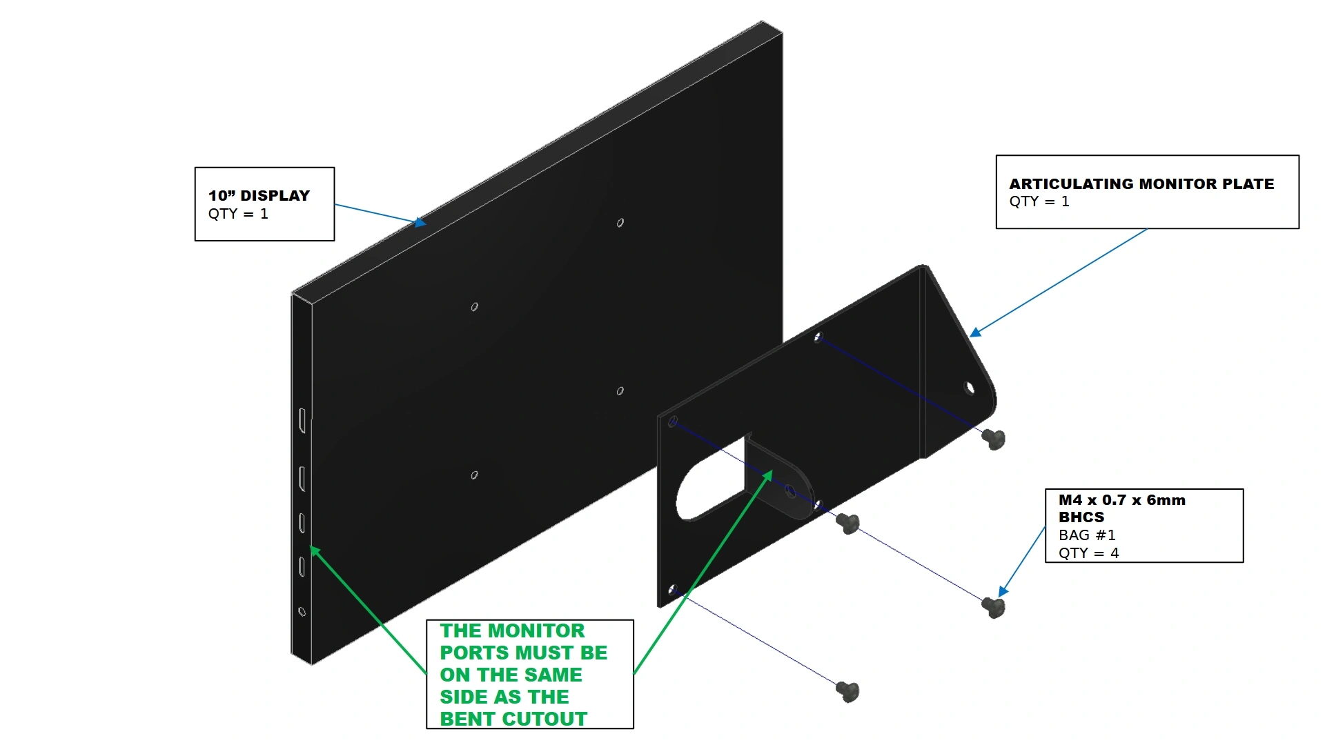
Instructions
- Locate the 10” Display and Articulating Monitor Plate that came with your pro-electronics kit.
- Using the fasteners shown, secure the Articulating Monitor Plate to the back of the 10” Display with a 2.5mm hex key such that the Monitor’s ports are on the same side as the bent cutout of the plate.
Materials
Parts
- (1) Monitor Mount Plate
Hardware
- (1) M5 x 0.8 x 100mm BHCS
- (1) M5 x 0.8 Serrated Flange Nut
Tools
- 3mm Hex Key
- 8mm Socket
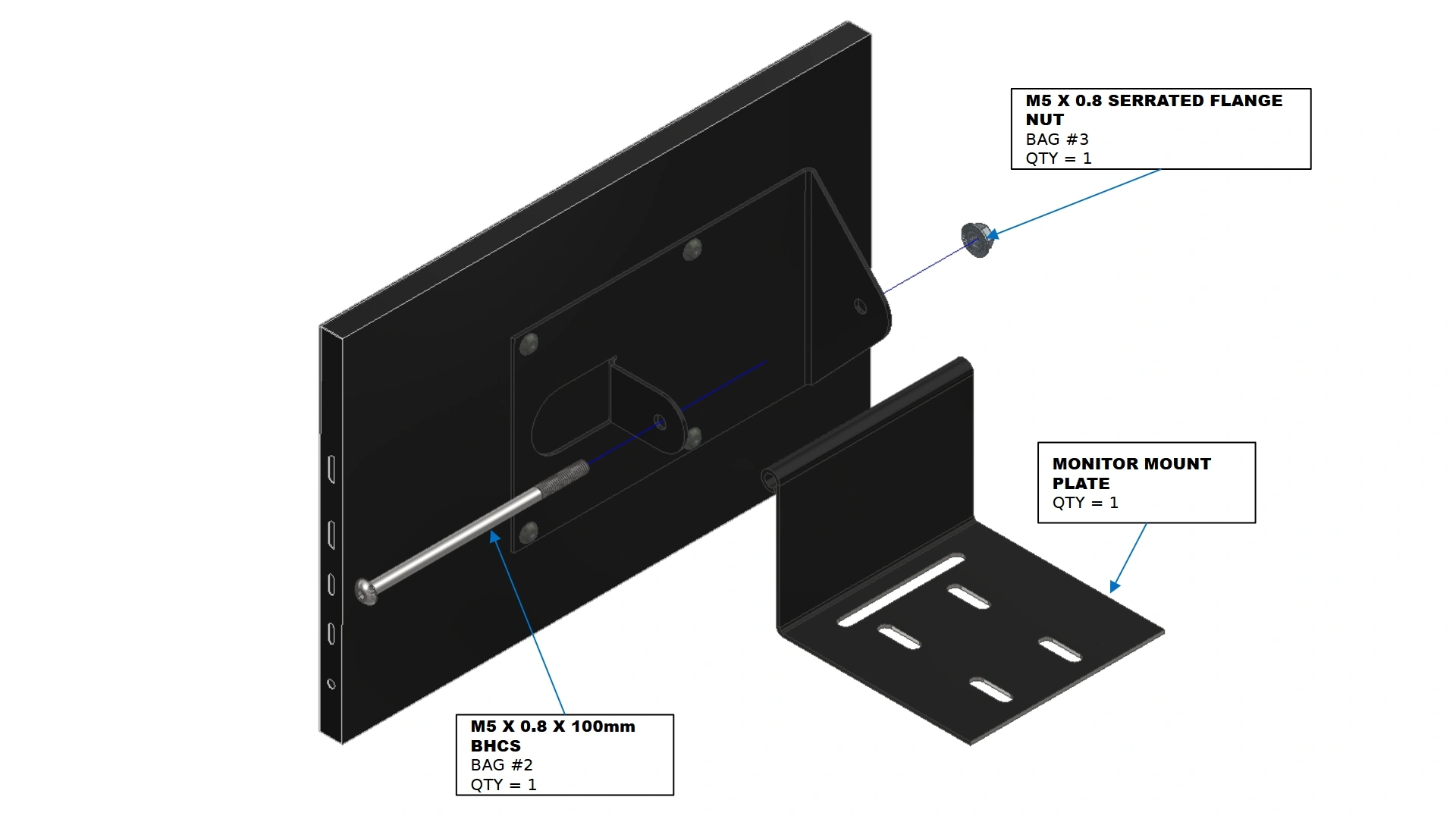
Instructions
- Locate the Monitor Mount Plate that came with your Pro-Electronics Kit
- Using the fasteners shown, secure the Monitor to the Mounting plate at the desired angle when operating the unit. Tightening the M5 nut and bolt will lock the rotation of the monitor.
Materials
Parts
- (1) Monitor Assembly
- (1) Electronics Enclosure
Hardware
- (4) M5 x 0.8 x 10mm BHCS
Tools
- 3mm Hex Key
Instructions
- Using a 3mm hex key, remove the bolt on the top of the electronics enclosure that is closest to the front ports.
- Using the threaded inserts at the top of the electronic box’s front cover, secure the monitor mount plate to the top of the box with the fasteners shown.
- Return the removed bolt from the electronics box to its original location, passing through the slot feature of the Monitor Mount Plate.
5: Touch Screen Wiring
The next step is to connect the monitor to the respective ports on the electronics enclosure.
Materials
Parts
- (1) Monitor Power Cable (Included with Monitor)
- (1) Monitor Display Cable (Included with Monitor)
Hardware
- Cable Tie Mount (3)
- Cable Tie (3)
Tools
- N/A
Instructions
- Locate the Monitor Display Cable & Monitor Power Cable that came with your 10” Display.
- Wire the Monitor Display Cable (HDMI to mini-HDMI) between the port on the enclosure that reads “Screen HDMI” and the port on the monitor that reads “DISPLAY”
- Wire the Monitor Power Cable Between the USB-A Panel Interconnect labeled “Screen Power” and the USB-C port on the monitor that reads “POWER”
- Route the remaining USB-A to USB-C cable between either of the USB panel mounts on the electronics box to the “Touch” port on the monitor.
- Using the provided cable tie mounts and cable ties, feel free to add cable management for the loose wires.
6: Electronics Enclosure
The Final step is to close the mount and close the box
Materials
Parts
- (1) Electronics Enclosure
Hardware
- (12) M5 x 0.8mm x 10mm BHCS
Tools
- 3mm Hex Key
Instructions
Note
If you have not mounted the electronics box to your unit, do so now. You can reference how to mount the box in our Vulcan 16 Assembly Guide →
- Locate the Electronics Enclosure Front Panel that was set aside earlier as well as the 12 BHCS.
- Using a 3mm Hex Key, re-install the front cover with the 12 BHCS.
Vulcan 16 Mesh Fixture Add-on
Images in this Guide
The assembly drawings and pictures included in this guide can be expanded to
full-screen and zoomed to provide more detail on a given step.
1: Roller Bearings
The first step in the assembly is to install the roller bearings onto the fixture.
Materials
Parts
- (6) Studded Roller Bearings
Hardware
- (6) M8 x 1.25 Thin Hex Nut
Tools
- N/A
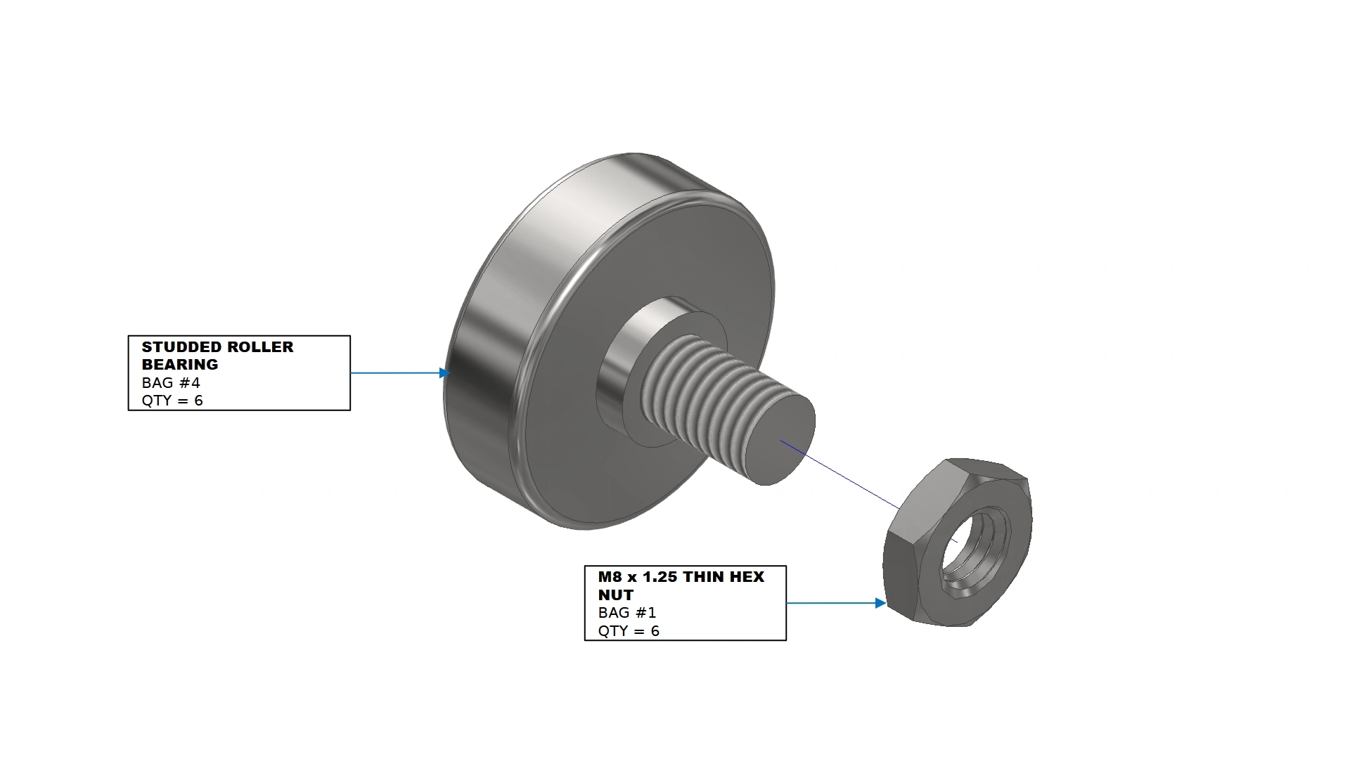
Instructions
- Locate the six Studded Roller Bearings that came with your kit.
- Install a thin hex nut onto the stud of each bearing.
- Repeat for all studded roller bearings.
Materials
Parts
- (6) Studded Roller Bearings w/ nut
- (1) Frame Weldment Assembly
Hardware
- (6) M8 x 1.25 Thin Hex Nut
Tools
- 6mm Hex Key
- 13mm Box end wrench
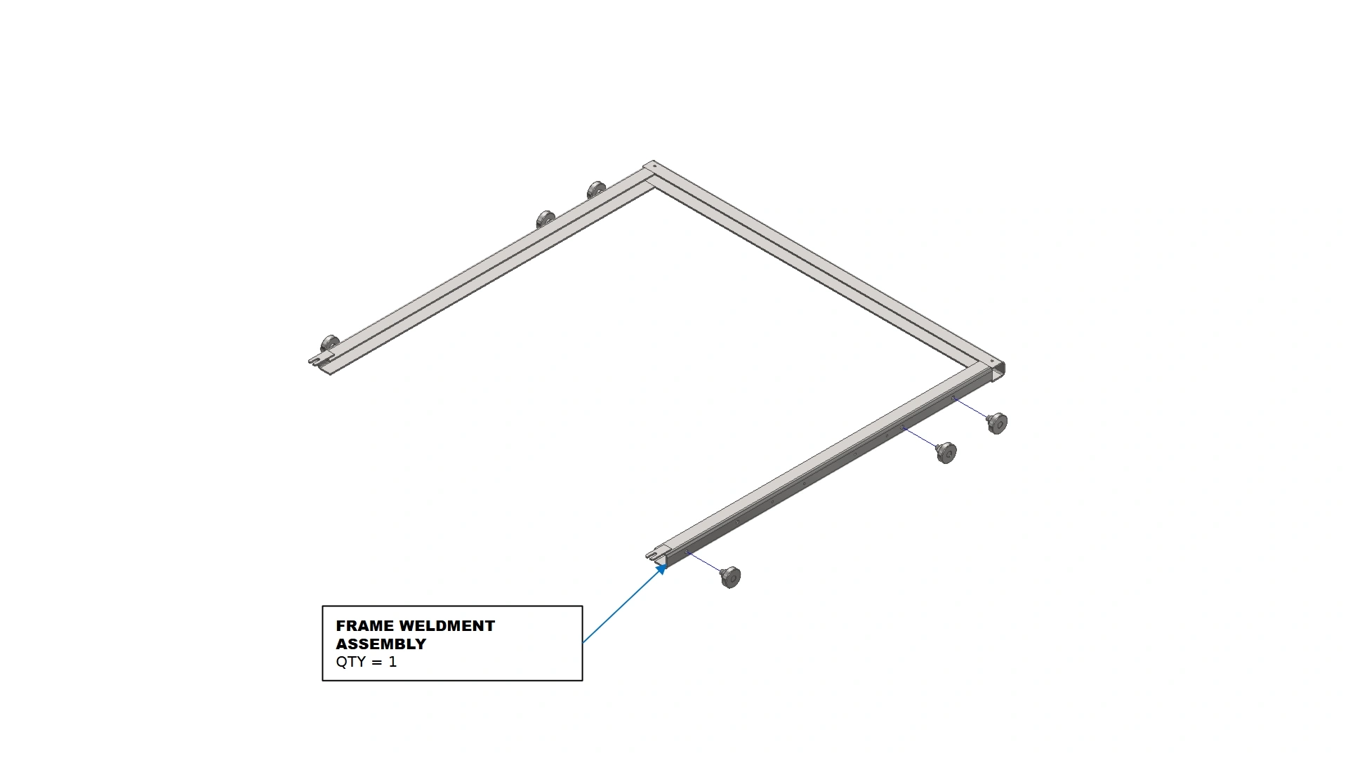
Instructions
- Locate the Frame Weldment Assembly that came with your kit.
- Using the threaded hole locations on the side of the weldment, install the roller bearings with a 6mm Hex Key.
- Repeat for all studded roller bearings.
- Adjust each roller bearing to the same amount of stick out. Once in place, tighten the M8 nut using a 13mm box end wrench to secure the bearing in place.
2: The Wire Mesh
The second step in the assembly is to insert and secure the wire mesh
Materials
Parts
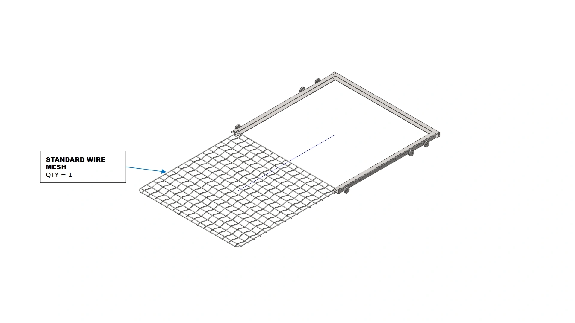
- (1) Standard Wire Mesh
Hardware
- N/A
Tools
- N/A
Instructions
- Locate the Standard Wire Mesh that came with your kit.
- Insert the wire mesh into the C-channel formed by the frame weldment.
Materials
Parts
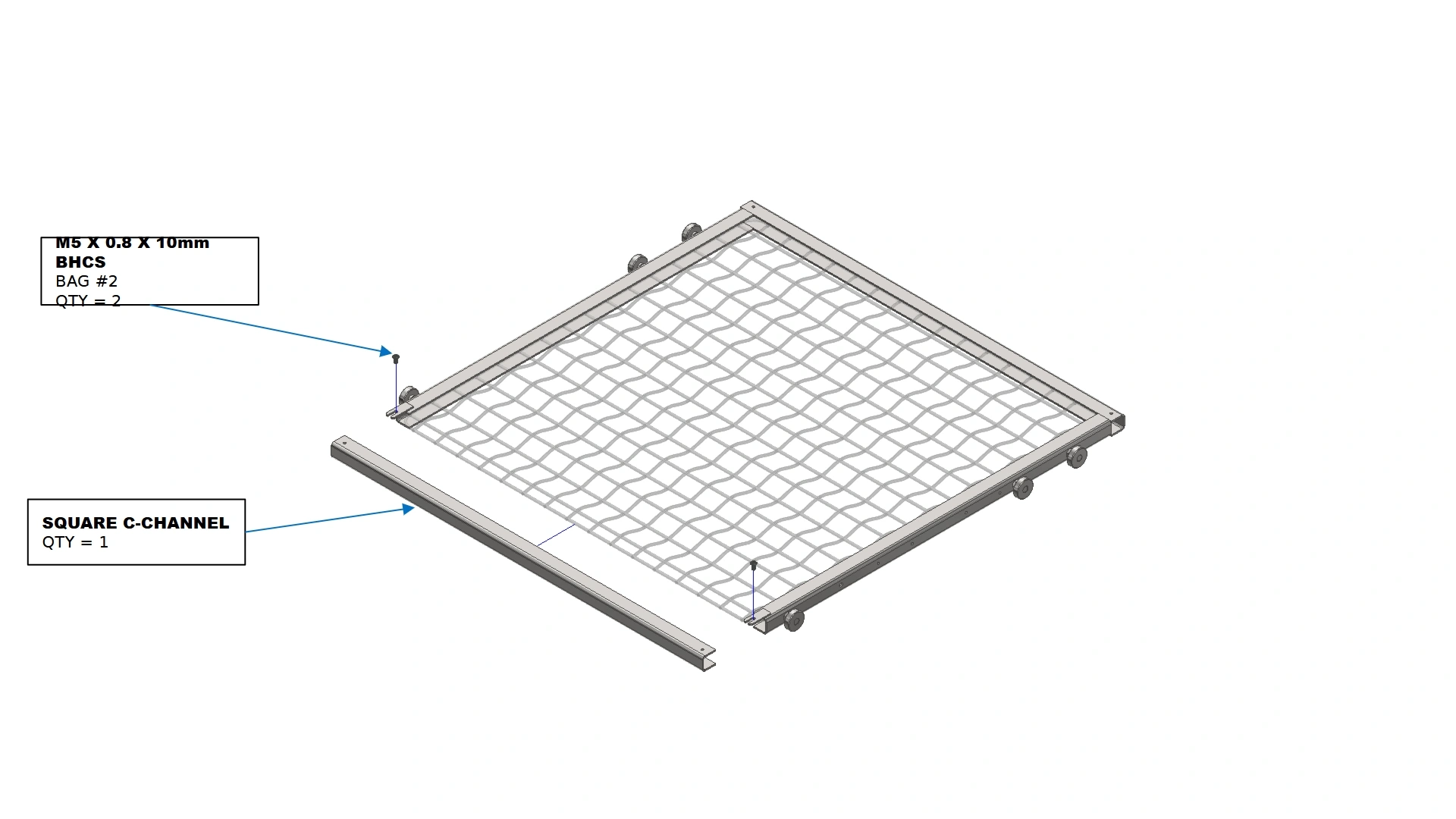
- (1) Square C-Channel
Hardware
- (2) M5 x 0.8 x 10mm BHCS
Tools
- 3mm Hex Key
Instructions
- Secure the wire mesh in place with the Square C-Channel in your kit.
- Fasten the C-Channel in place using the fasteners shown with the slotted weld tabs on the frame.
3: Installation
The final step in the assembly is to install the bearing tracks and place the fixture into the Vulcan.
Materials
Parts
- (1) Vulcan 16
Hardware
- N/A
Tools
- 4mm or 5/32 Carbide Drill bit
- Cutting Oil
- Drill
- Rubbing Alcohol
Instructions
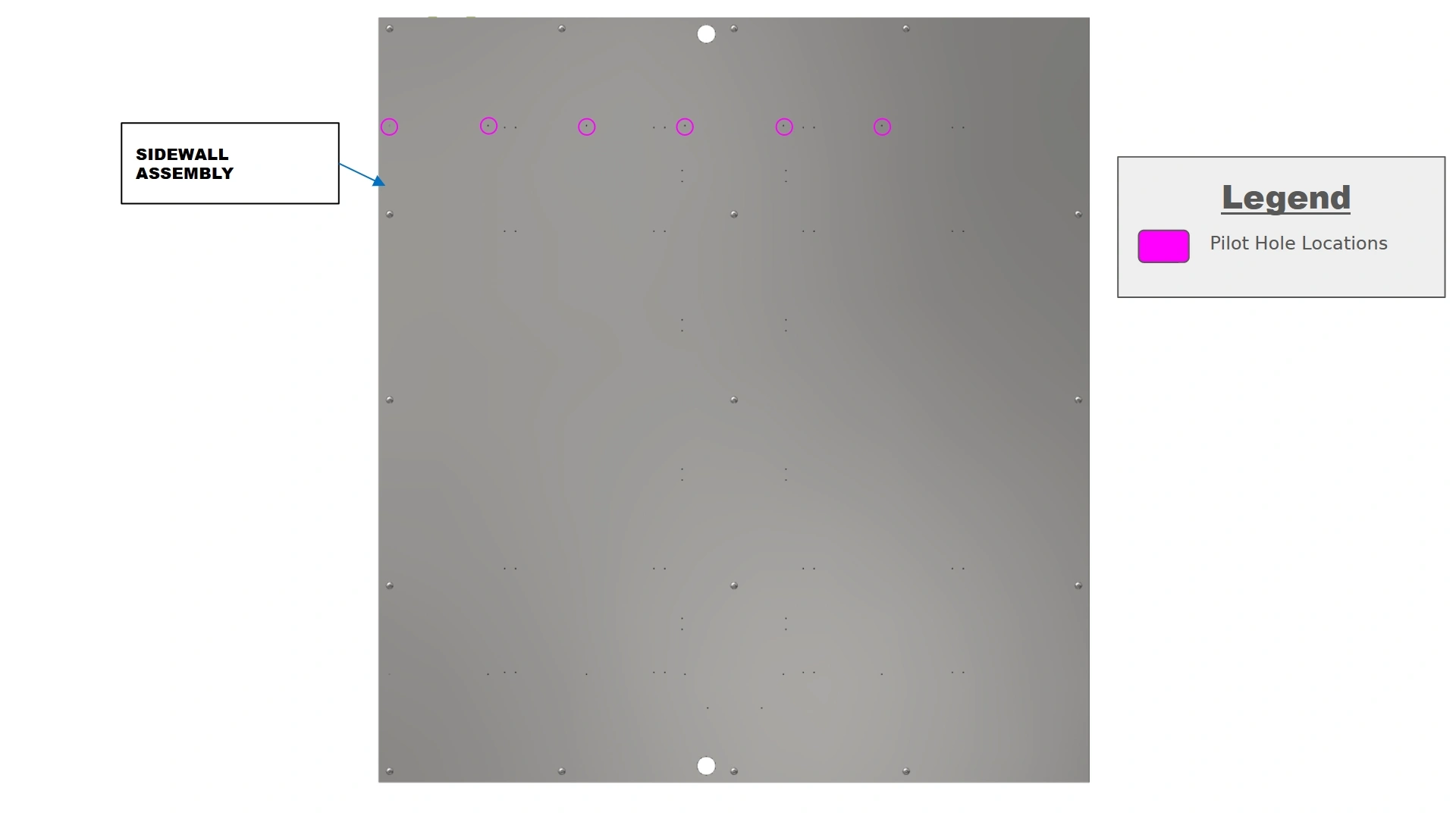
- Look inside your Vulcan 16 and locate the provided pilot hole locations on your sidewalls. Use the provided image as a reference to easily locate the pilot holes.
- The provided pilot holes are approximately 1mm in diameter. They will need to be bored out further for ease of installation.
![]() PERSONAL PROTECTIVE EQUIPMENTCarbide drill bits are extremely susceptible to fracture and can eject sharp carbide during drilling. It is imperative to wear safety glasses during this process to avoid serious injury.
PERSONAL PROTECTIVE EQUIPMENTCarbide drill bits are extremely susceptible to fracture and can eject sharp carbide during drilling. It is imperative to wear safety glasses during this process to avoid serious injury.![]() NoteStainless steel is extremely resistant to drilling operations, making this a time intensive process. The use of cutting oil during drilling will prevent work hardening due to heat generated by friction. If you are new to carbide drill bits, go slowly and obtain a feel for the cut to ensure the longevity of your bit.NoteThe plates are not symmetrical while the sidewall assemblies are. Two hole locations have been provided to ensure proper alignment during installation. During drilling, ensure you use the same holes on both sidewalls to avoid misalignment of the plates. As an example, if mounting in the horizontal position on the left-hand wall AND using the leftmost pilot holes (closest to the door), when mounting to the right-hand wall, you would use the rightmost holes (closest to the door) to properly mirror the locations.
NoteStainless steel is extremely resistant to drilling operations, making this a time intensive process. The use of cutting oil during drilling will prevent work hardening due to heat generated by friction. If you are new to carbide drill bits, go slowly and obtain a feel for the cut to ensure the longevity of your bit.NoteThe plates are not symmetrical while the sidewall assemblies are. Two hole locations have been provided to ensure proper alignment during installation. During drilling, ensure you use the same holes on both sidewalls to avoid misalignment of the plates. As an example, if mounting in the horizontal position on the left-hand wall AND using the leftmost pilot holes (closest to the door), when mounting to the right-hand wall, you would use the rightmost holes (closest to the door) to properly mirror the locations. - With a carbide drill bit and cutting oil, work your way around to each mounting hole location on both sidewalls and increase the diameter of the hole until it is slightly undersized to the provided M5.5 fasteners provided in your kit.
- Use rubbing Alcohol to remove residual cutting oil from the walls surface.
NoteFailure to wipe oil off the surface before running the oven can be a significant fire hazard. Ensure your surface is clean and ready for operation before turning on the heat element.
Materials
Parts
- (1) LH Roller Track
- (1) RH Roller Track
Hardware
- (12) M5.5 x 19mm HHDS
Tools
- 8mm Socket
- Impact Driver
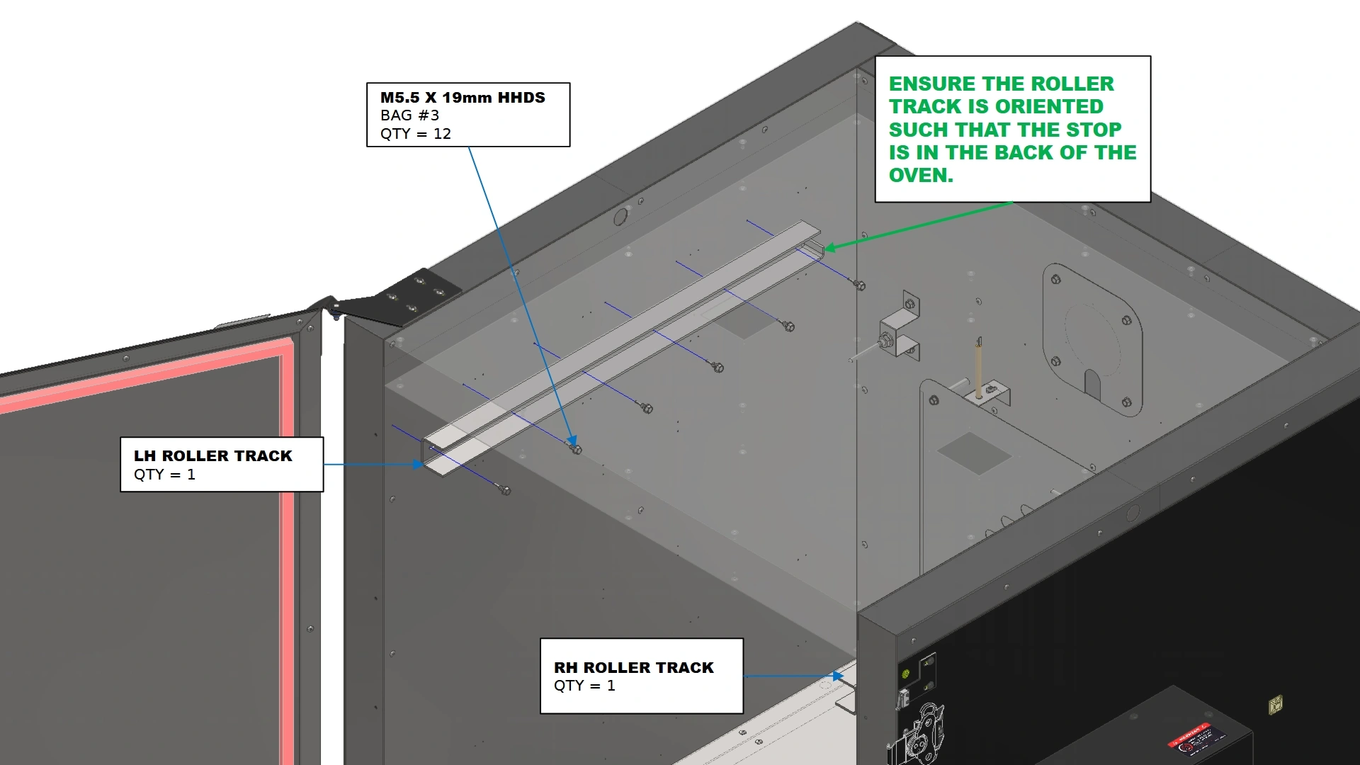
Instructions
ORIENTATION
Ensure the roller tracks are oriented correctly by placing the retaining flange towards the back of the oven.
- Using the fasteners shown, secure the roller track to the sidewalls such that the open face of the C-Channel track is flush with the door frame.
- Repeat B1 for the remaining roller track
Materials
Parts
- (1) Variable Mesh Fixture
Hardware
- N/A
Tools
- 13mm Crescent Wrench
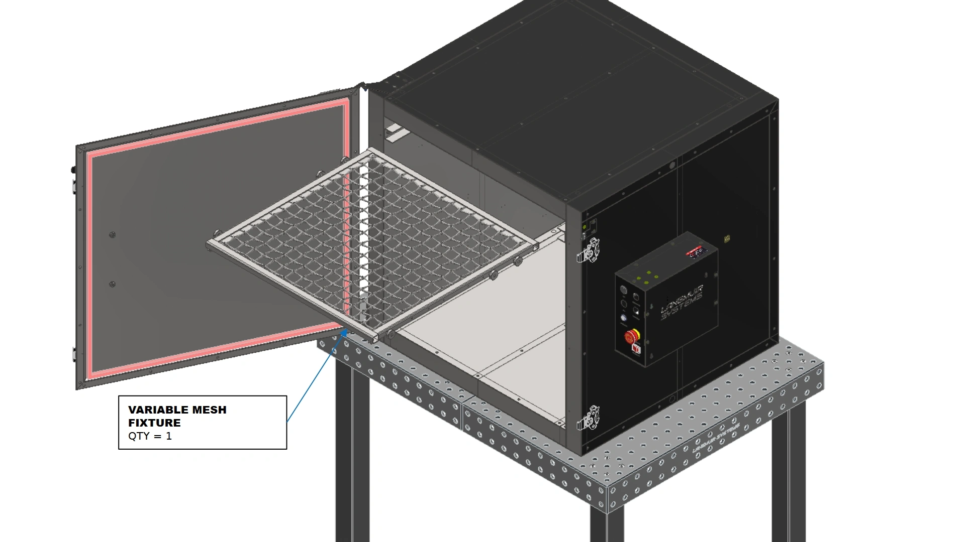
Instructions
- Insert the Variable mesh fixture into the roller tracks with the extended end oriented to the back of the oven.
- If needed, adjust the depth of the studded roller bearings by turning the threads to either extend or retract their stick out distance.
- Once adjusted, use a 13mm crescent wrench to tighten the M8 Thin Hex Nut on the stud and prevent movement of the rollers.
Vulcan Fixturing Cart Assembly
Images in this Guide
The assembly drawings and pictures included in this guide can be expanded to
full-screen and zoomed to provide more detail on a given step.
1: Frame Assembly
The first step in assembling the Fixture cart is to create the frame.
Materials
Parts
- (1) Cart Base Weldment
Hardware
- N/A
Tools
- N/A
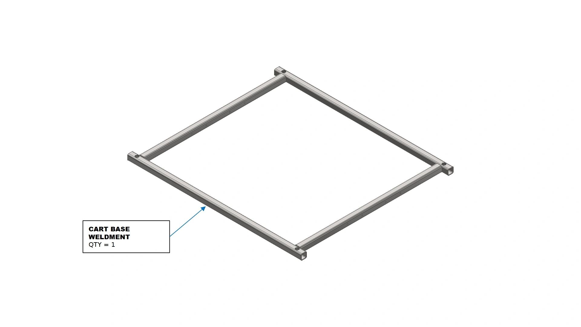
Instructions
- Locate the Cart Base Weldment that came with you Fixture Cart Kit.
Materials
Parts
- (1) Cart Base Weldment
- (1) Vertical Support Tube
- (1) Cart Support Flange
Hardware
- (6) M5 x 0.8 x 10mm BHCS
Tools
- 3mm Hex Key
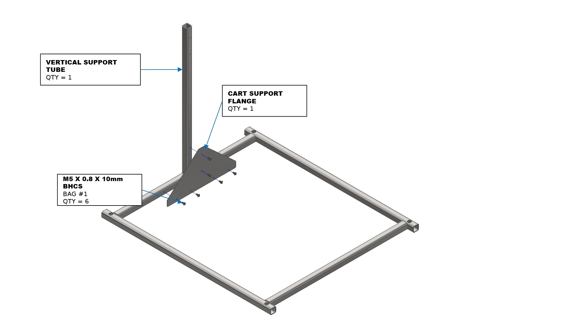
Instructions
- Locate one of the Vertical Support Tubes and Cart Support Flanges in your kit.
- Using the cart support flange, secure the vertical support tube in place with the fasteners shown.
Materials
Parts
- (1) Cart Support Flange
Hardware
- (6) M5 x 0.8 x 10mm BHCS
Tools
- 3mm Hex Key
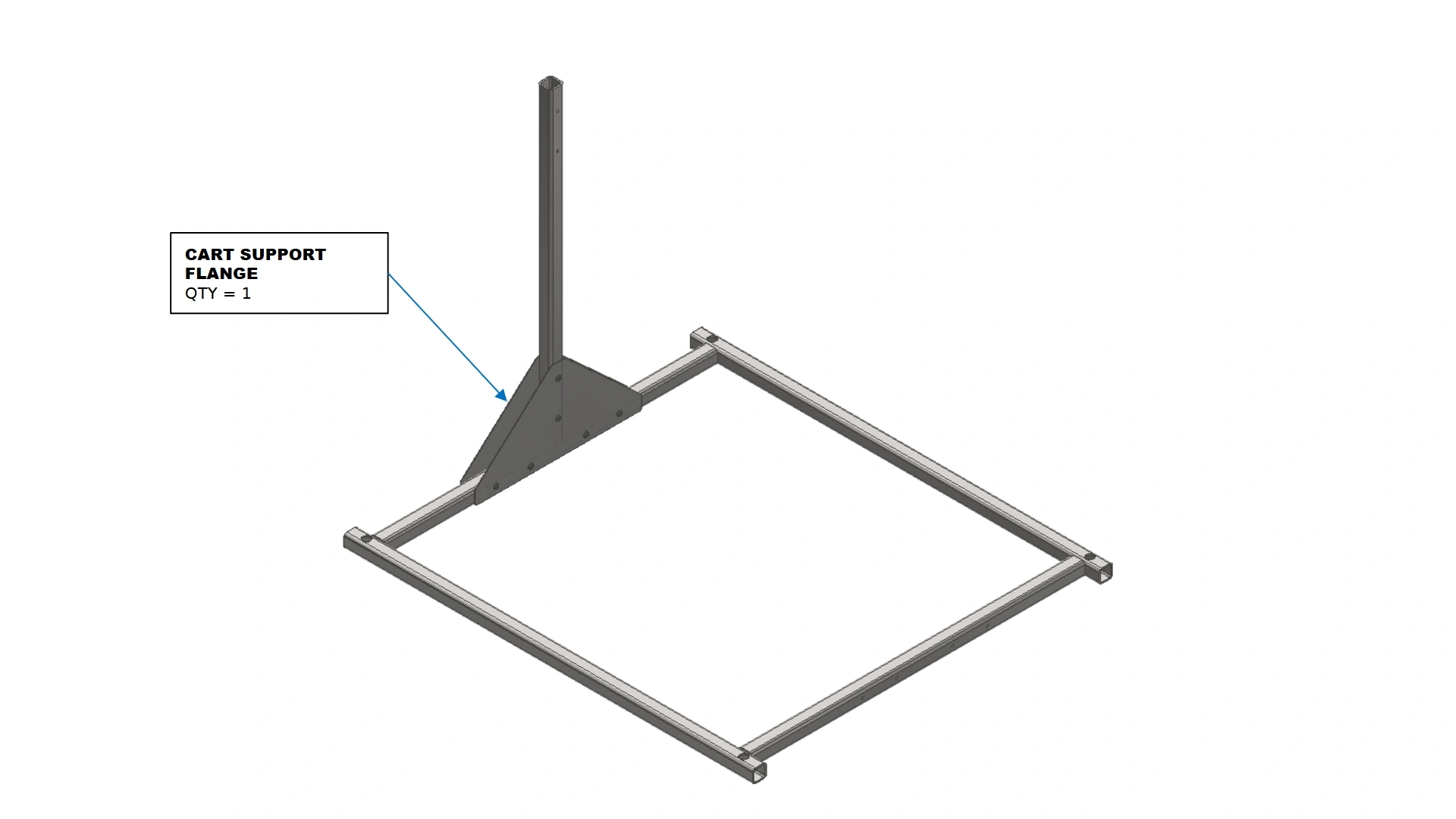
Instructions
- Repeat step B2 for the other side of the vertical support tube.
Materials
Parts
- (1) Cart Base Weldment
- (1) Vertical Support Tube
- (2) Cart Support Flange
Hardware
- (8) M5 x 0.8 x 10mm BHCS
Tools
- 3mm Hex Key
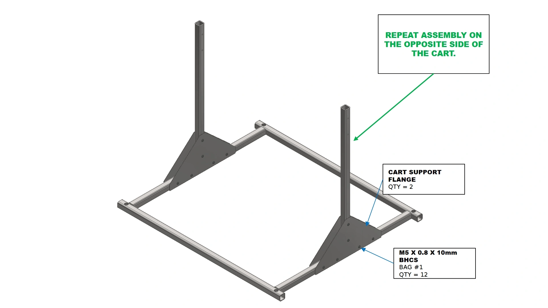
Instructions
- Repeat steps B1-C1 for the opposite side of the cart base weldment.
Materials
Parts
- (1) Cart Support Flange
Hardware
- (2) M5 x 0.8 x 10mm BHCS
Tools
- 3mm Hex Key
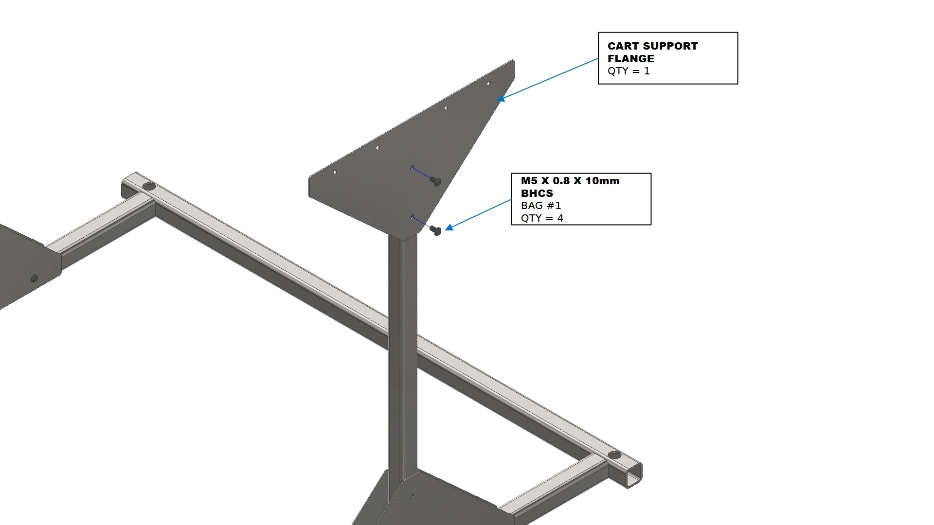
Instructions
- Locate another Cart Support Flange.
- Using the fasteners shown, secure the flange to the side of the vertical support tube on the outside of the assembly.
Materials
Parts
- (1) Cart Support Flange
Hardware
- (2) M5 x 0.8 x 10mm BHCS
Tools
- 3mm Hex Key
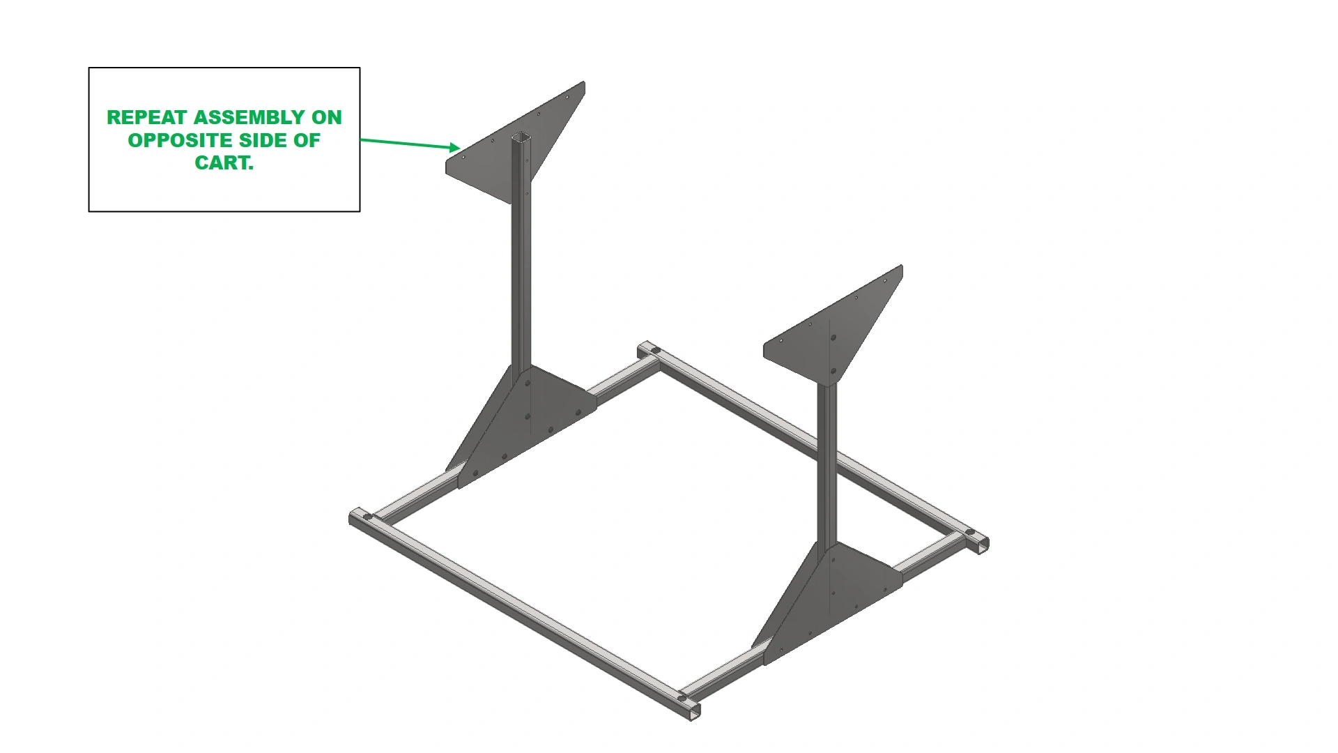
Instructions
- Repeat steps E1 and E2 for the other side of the cart.
Materials
Parts
- (1) Frame Weldment Assembly
Hardware
- (8) M5 x 0.8 x 10mm BHCS
Tools
- 3mm Hex Key
Instructions
- Locate the Frame Weldment Assembly.
- Using the fasteners shown, secure the frame weldment assembly to the vertical supports and cart flanges.
2: Installing the Casters
The next step in the assembly process is to install the casters
Materials
Parts
- (4) High Temperature Casters
Hardware
- N/A
Tools
- N/A
Instructions
- Locate the High Temperature Caster Wheels.
- Using the threaded holes on the cart base weldment, fasten the casters in place.
3: The Mesh Tray
The last step in the assembly process is installing the mesh tray.
Materials
Parts
- (1) Wire Mesh
Hardware
- N/A
Tools
- N/A
Instructions
- Locate the Wire Mesh that came with you kit.
- Using the open face of the Frame Weldment on the top of the cart, slide the wire mesh into place until.
Materials
Parts
- (1) Square C- Channel
Hardware
- (2) M5 x 0.8 x 10mm BHCS
Tools
- 3mm Hex Key
Instructions
- Locate the Square C-Channel piece included with the Frame Weldment.
- Using the slotted weld tabs on the cart and thread features in the C-Channel, secure the channel in place such that the wire mesh is fully enveloped on all sides.
- The cart is now completed
4: Operating the Cart
A brief note about operating the Fixture Cart
Materials
Parts
- (1) Assembled Fixture Cart
- (2) Cart Ramps
Hardware
- N/A
Tools
- N/A
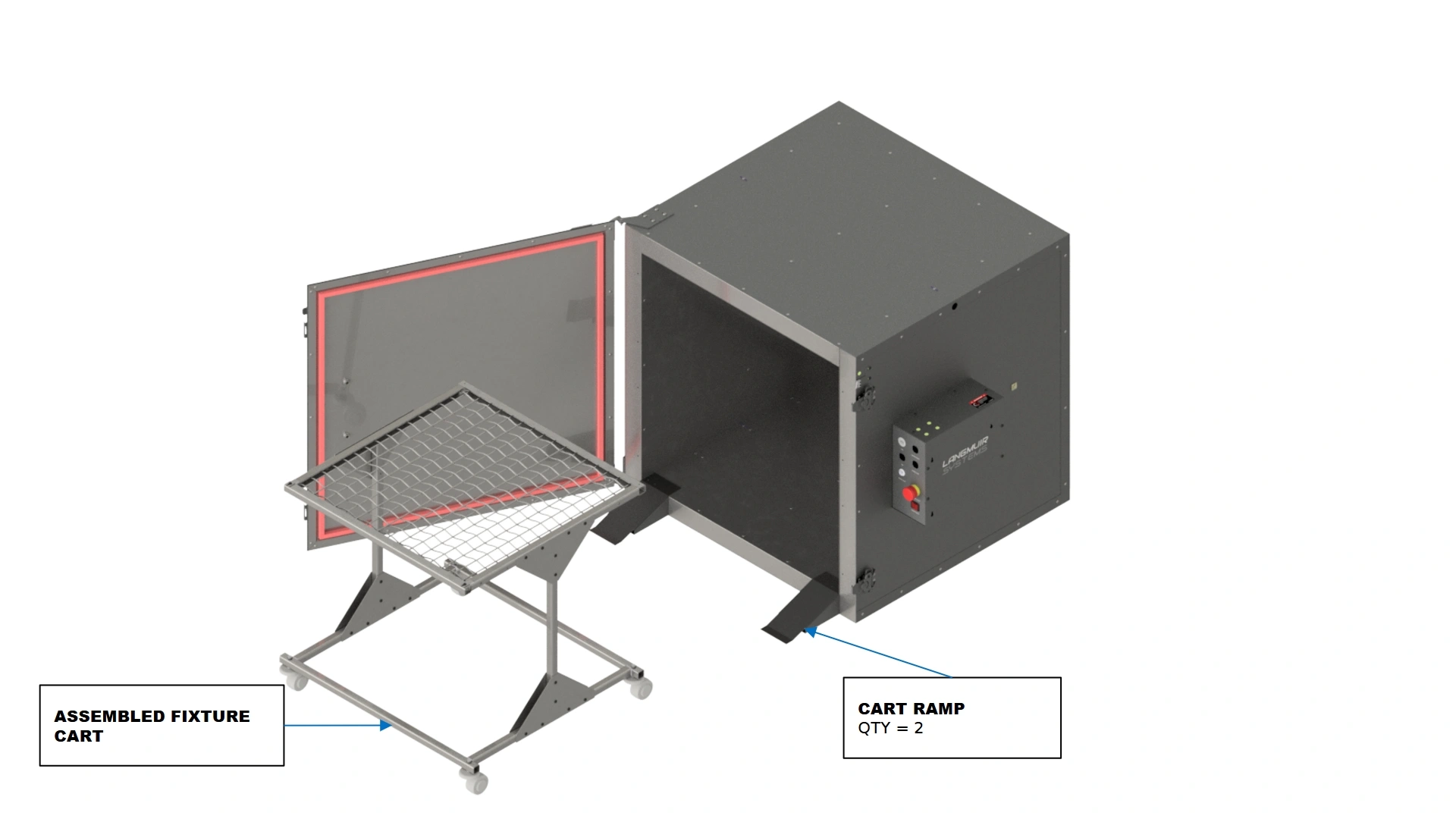
Instructions
Note
The fixturing cart is designed for versatility with heavier items. The gauge of wire used in the wire mesh will greatly determine the weight the cart can support. Additionally, the fixturing cart kit is intended only for benchtop or free standing use. If your oven is mounted onto the leg kit, the cart will be rendered inoperable without a means to easily load into the oven.