Apollo Assembly Guide
Safety
When used correctly, the Langmuir Systems Vulcan16 will offer you years of safe operation. However, like all other automated and industrial type machinery, there are important safety considerations and precautions that must be followed in order to avoid injury. Study these safety warnings carefully before assembling and using your machine.

ELECTRIC SHOCK
Electric shock can cause serious injury or death. This machine requires the use of high voltage electricity to operate. To avoid injury, always adhere to the following precautions:
- Never touch bare wires/buses/connections or components that are carrying electricity.
- Repair or replace all worn or damaged components. Turn off power to machine and plasma cutter when making repairs.
- Install and maintain equipment in accordance with the National Electric Code (NEC)
- If you have limited electrical knowledge/experience, hire a certified electrician to perform all electrical work.

FIRE AND EXPLOSION
Fire and explosion can be caused by the airborne sparks and slag igniting a nearby flammable material. Electrical fires can be caused if the machine is assembled or used incorrectly. To avoid injury, always adhere to the following precautions:
- Never operate the machine in the vicinity of flammable materials or where there is volatile and combustible fumes in the air.
- Do not use the machine to cut materials or parts that have previously contained fuel or flammable substance of any kind such as gas tanks.
- Always keep a fire extinguisher nearby in case of emergency.
- Never operate the machine in a poorly ventilated area.

HAZARDOUS FUMES
Gases and fumes produced during the plasma cutting process can be hazardous to your health. To avoid injury, always adhere to the following precautions:
- Keep all fumes and gases from the area in which you breathe. Never operate the machine in an area with minimal or no ventilation. Use fans and blowers to remove fumes and gases from the work area.
- If ventilation is poor, use an air-supplied respirator system.
- The type of fumes and hazard level depends greatly on the type of metal being cut. Before cutting, consult the Material Data Safety Sheet (MSDS) for specific guidelines on the type and hazard level of the fumes produced during cutting.
- Never cut materials that has been coated with paint, oil, grease, or solvents.

ULTRAVIOLET AND INFRARED RADIATION
The Apollo produces high intensity visible and invisible light which can cause permanent eye damage. Avoid eye or skin exposure to direct or scattered radiation.
- Never operate the machine without the side walls and protective panels in place.
- Laser eye protection is recommended: OD8+ 190nm–450nm / 800nm–1100nm wavelength laser safety glasses.
- Wear gloves and suitable clothing to protect your skin at all times.
- Always alert bystanders before you begin cutting. Bystanders in the immediate vicinity must wear suitable eye and skin protection.

PINCH AND CRUSH POINTS
This machine can create pinch points during normal assembly. To avoid injury, always adhere to the following precautions:
- Do not place any part of your body in defined crush points on the machine when it is being assembled.
- Be aware of all areas of the machine that could potentially be a pinching hazard, such as nested flanges, hinge points, and add-on attachment areas.

HOT MATERIALS
The curing process uses extremely high temperatures to cure powder coat. As a result, the material will be very hot after curing which can cause burns. To avoid injury, always adhere to the following precautions:
- Always assume that metal resting on or in the machine is hot enough to cause severe burns.
- Always allow the metal to sufficiently cool before handling.
- Never handle hot metal with bare hands. Use gloves or tongs to remove material from the machine.
WARNING
This product can expose you to chemicals which are known to the State of California to cause
cancer, birth defects or other reproductive harm. For more information go to www.P65Warnings.ca.gov.
Customer Success Guide
Images in this Guide
The assembly drawings and pictures included in this guide can be expanded to
full-screen and zoomed to provide more detail on a given step.
1: Unloading the Apollo
How to safely move the Apollo off the delivery truck.
Materials
Parts
- None
Hardware
- None
Tools
- 4,400 pound forklift
- 6 foot (72 inch) forks or extensions
Instructions
NOTE
The center of gravity is located towards the hoop end (garage) of the machine. When lifting the Apollo the forks must be placed so the fork farthest from the garage end is just on the outside of the cart guide.
- Unloading should be performed from the operators side. This can be identified by the large Apollo CNC Fiber Laser decal.
- Locate the cart guide farthest from the garage.
- Carefully drive forks under the Apollo making sure the fork carriage is clear of the lower enclosure body and fully passes through the stringers for the legs. Care should be taken when lifting that the Apollo is not damaged by the fork carriage or is unbalanced on the forks.
- Lift the Apollo and drive to desired location and set gently in the shop.
Materials
Parts
- None
Hardware
- None
Tools
- 4mm Allen key
- #2 Phillips screwdriver
- Utility knife
Instructions
- Release and remove the ratchet straps. Using the utility knife, remove the plastic wrapping around the hoop (garage) and the parts bundle.
- Using the screwdriver and allen key, remove the wood blocking in the garage. Care should be taken not to damage the fiber optic cable. Replace the M6 button head cap screws once the gantry shipping brackets are removed.
- Unpack the parts kit and check for completeness. Monitors are packed inside of the bundle and the sheet metal for the roof will need to be removed to locate them.
-
Place components into separate areas for assembly. The order should be as follows:
- Roof components
- Doors
- Computer and monitor
- Camera and lighting kit (if purchased)
- Wagon
- Hook up kit (if purchased)
2: Final Assembly
This will set up your Apollo so that it will be ready to make its first cuts.
Recommended Tools List for Assembly
Apollo Assembly Tools
- Cordless Rivet Tool or One Hand Rivet Tool
- 1/8" Cleco Pins
- Cordless Drill, Step Drill Bit, and 1/8” Drill Bit
- Imperial and Metric Allen Wrench Sets
- Imperial and Metric Combination Wrench Sets
- Tape Measurer
- Philips Screwdriver Set
- Rubber Mallet
- 24” Bubble Level
Water Chiller Tools/Materials
- 6 Gallons of Distilled Water
- Funnel
- Plumber’s/Teflon Tape
- Tube Cutters
- Wire Stripper
- 25ft 10mm OD x 6.5mm ID Silicone Tubing and 25ft 12mm OD x 10mm ID Silicone Tubing (If Hook-Up Kit not Purchased)
- (2) 1/2" NPT x 12mm Push to Connect (If Hook-Up Kit not Purchased)
- (2) 1/2" NPT x 10mm Push to Connect (If Hook-Up Kit not Purchased)
Gas Connection Tools for O2 and N2
- Oxygen and/or Nitrogen Bottles (depending on usage)
- Bottle Rack/Storage Solution
- Oxygen or Nitrogen Regulator
-
Oxygen Flashback Arrestor for Oxygen System (If Hook-up Kit not Purchased)
- VERY IMPORTANT
- 37° Flared Fitting for Oxygen system (If Hook-Up Kit not Purchased)
- (2) 1/4" NPT x 10mm Push to Connect (If Hook-Up Kit not Purchased)
- 50ft - 10mm OD x 8mm ID Hard Nylon Tubing (If Hook-up Kit not Purchased)
Recommended Apollo Assembly Order
- Assemble the Roof - https://www.langmuirsystems.com/apollo/assembly#ac2
- Instal the Roof - https://www.langmuirsystems.com/apollo/assembly#ac3
- Put on the Doors and Check Square - https://www.langmuirsystems.com/apollo/assembly#ac4 | https://www.langmuirsystems.com/apollo/assembly#ac5
- Mount the Monitor - https://www.langmuirsystems.com/apollo/assembly#ac6
- Set up the Computer - https://www.langmuirsystems.com/apollo/assembly#ac10
- Assemble the Retrieval Cart - https://www.langmuirsystems.com/apollo/assembly#ac7
- Check Limits and Home Machine - https://www.langmuirsystems.com/apollo/assembly#ac11 | https://www.langmuirsystems.com/apollo/assembly#ac12
- Fill and Hook Up Chiller - https://www.langmuirsystems.com/apollo/assembly#ac8
- Connect Gas Bottles - https://www.langmuirsystems.com/apollo/assembly#ac9
- Camera and Lighting Kit Add-on - https://www.langmuirsystems.com/apollo/assembly#apollo-camera-light
3: First-Time User Setup & Operation
This guide outlines the recommended steps for first-time operation of your Apollo system. Followingthese instructions will help ensure safe operation, proper machine setup, and optimal cuttingperformance.
IMPORTANT – Zero Position Requirement
If LaserControl resets or the system is powered down, you MUST re-establish the zero position before continuing operation.
Failure to reset the zero potions can result in the following: Incorrect machine movement, Loss of positional accuracy, and Damage to the machine or cutting material. Always perform a "Zero All Axes" command after restarting LaserControl or powering the machine on. This step ensures the system has a correct reference point for all movement and cutting operations.
Failure to reset the zero potions can result in the following: Incorrect machine movement, Loss of positional accuracy, and Damage to the machine or cutting material. Always perform a "Zero All Axes" command after restarting LaserControl or powering the machine on. This step ensures the system has a correct reference point for all movement and cutting operations.
1. Initial System Setup
Before beginning operation, ensure the machine and software environment are properly initialized.This step prepares the system for safe and accurate operation.
- Power on the Apollo system and verify all components initialize correctly
- Launch the LaserControl software and confirm communication with the machine
- Load your material securely onto the cutting bed, ensuring it is flat and stable
- Visually inspect the work area for obstructions or loose items
2. Set the Zero Position
Establishing a zero position provides the machine with a reference point for all motion and cuttingoperations. This is one of the most critical steps in the setup process.
- Verify the Z-axis (laser head) has sufficient clearance before moving
- Position the laser head directly at the material surface
- Select “Zero All Axis” in LaserControl to define the reference position
- Repeat this process any time the machine position is changed or reset
3. Prepare Personal Protective Equipment (PPE)
Proper safety equipment is required at all times when operating the Apollo system to protect againsthazards associated with laser cutting.
- Wear approved safety goggles designed for laser operation
- Use a respirator or gas mask when cutting materials that produce fumes
- Wear appropriate work gloves when handling materials
- Ensure all PPE is properly fitted and in good condition before use
4. Verify Air and Cooling Systems
The Apollo system relies on proper gas flow and cooling to maintain cutting performance andprevent damage to components.
- Turn on your selected gas supply (On, Nn, or air compressor)
- Confirm the chiller is powered on and functioning (if equipped)
- Use the “Burst Gas” function in LaserControl to verify airflow through the laser head
- Listen and visually confirm consistent airflow before proceeding
5. Load and Position Your Program
Accurate positioning and program setup ensure your cuts are placed correctly on the material andwithin machine limits.
- Use the X and Y directional controls to move the torch head
- Operate at a controlled speed (recommended approximately 250 IPM) for safe positioning
- Load your desired cut program into LaserControl
- Select “Zero All Axis” after loading the program
- Confirm the torch head remains within machine travel limits
- Re-zero the machine after any manual adjustments to positioning
6. Set Cutting Parameters
Before cutting, the system must be configured to match the selected material and cuttingconditions.
- Run CHS Control (this process may take several minutes to complete)
- Run AF Control to calibrate the system
- Load appropriate Material Properties to match your material type and thickness
- Verify all parameters before proceeding to cutting
7. Begin Cutting Operation
Once all setup steps are complete, you may begin the cutting process.
- Put on all required PPE before starting the laser
- Notify all personnel in the area that cutting is about to begin
- Turn on the laser source using the provided key
- Press the control button to arm the laser and begin operation
8. Monitor the Cutting Process
Continuous monitoring ensures proper operation and allows you to identify any issues early.
- Observe cutting speed and adjust if necessary
- Listen for consistent and uninterrupted gas flow
- Monitor LaserControl for progress and estimated completion time
- Be prepared to stop the machine if any irregularities occur
4: Contact Us
After assembly is complete, you can schedule a virtual inspection and walkthrough of the machine with one of our engineers.
Langmuir Systems Contact Info
- Email: support@langmuirsystems.com
- Phone: 833-526-4797
- When: Monday-Friday, 9am-4:30pm CST
- Make sure assembly is fully finished and that air, electrical, and mechanical components are ready to fire before scheduling the virtual walkthrough. Appointments may be delayed or halted early if more assembly is required.
Apollo Assembly Guide
Images in this Guide
The assembly drawings and pictures included in this guide can be expanded to
full-screen and zoomed to provide more detail on a given step.
1: Removal From Flatbed
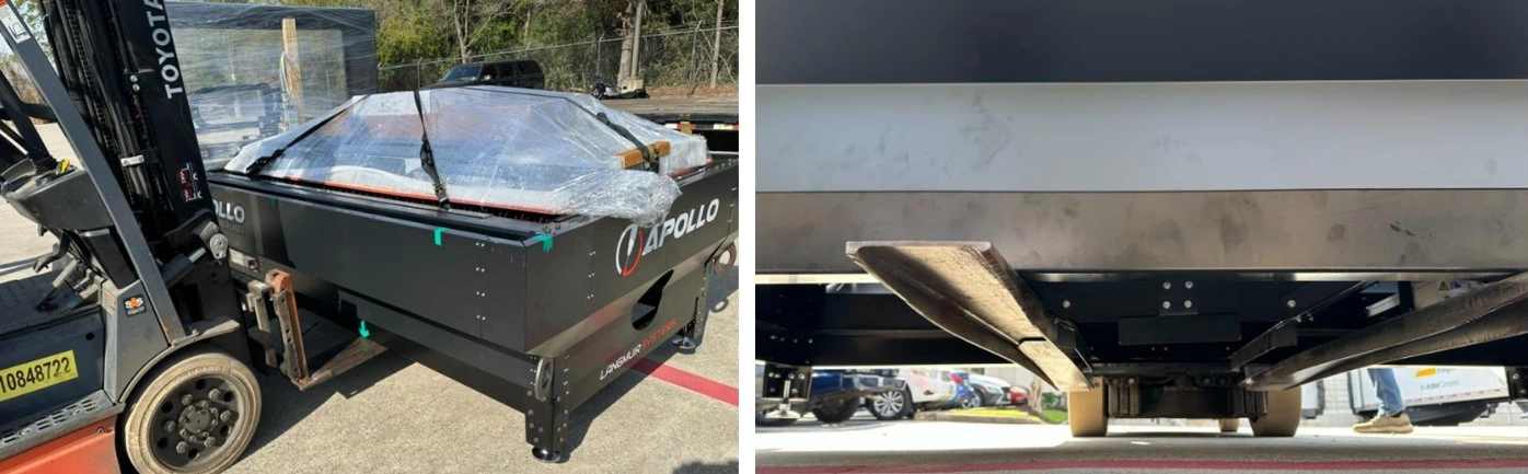
The Apollo CNC Fiber Laser is delivered on a Flatbed, with all user assembled components and add ons shipped inside the cut bed. The water chiller is secured to the bed separately from the laser table.
Materials
Parts
- None
Hardware
- None
Tools
- 4,400 pound forklift
- 6 foot (72 inch) forks or extensions
Instructions
NOTE
The center of gravity is located towards the hoop end (garage) of the machine. When lifting the Apollo the forks must be placed so the fork farthest from the garage end is just on the outside of the cart guide.
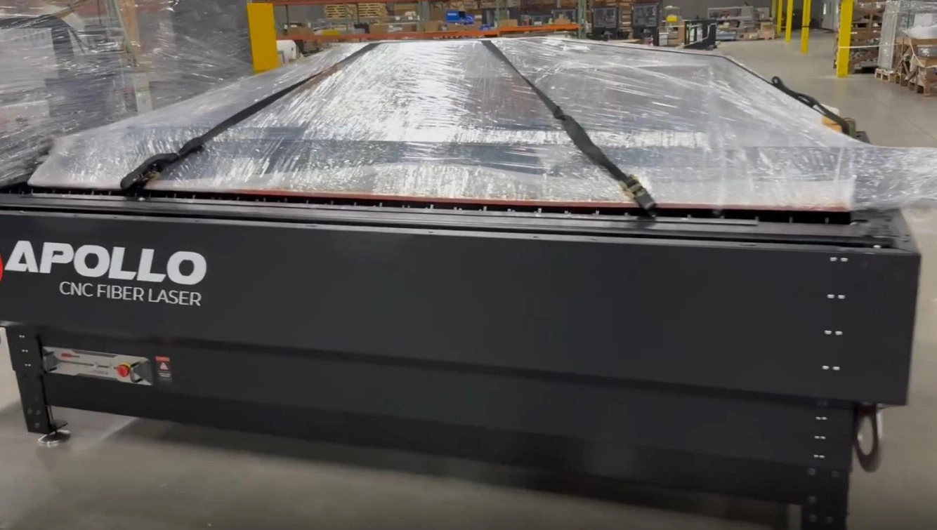
- Unloading should be performed from the operators side. This can be identified by the large Apollo CNC Fiber Laser decal.
- Locate the cart guide farthest from the garage.
- Carefully drive forks under the Apollo making sure the fork carriage is clear of the lower enclosure body and fully passes through the stringers for the legs. Care should be taken when lifting that the Apollo is not damaged by the fork carriage or is unbalanced on the forks.
- Lift the Apollo and drive to desired location and set gently in the shop.
Materials
Parts
- None
Hardware
- None
Tools
- 4mm Allen key
- #2 Phillips screwdriver
- Utility knife
Instructions
- Release and remove the ratchet straps. Using the utility knife, remove the plastic wrapping around the hoop (garage) and the parts bundle.
- Using the screwdriver and allen key, remove the wood blocking in the garage. Care should be taken not to damage the fiber optic cable. Replace the M6 button head cap screws once the gantry shipping brackets are removed.
- Unpack the parts kit and check for completeness. Monitors are packed inside of the bundle and the sheet metal for the roof will need to be removed to locate them.
-
Place components into separate areas for assembly. The order should be as follows:
- Roof components
- Doors
- Computer and monitor
- Camera and lighting kit (if purchased)
- Wagon
- Hook up kit (if purchased)
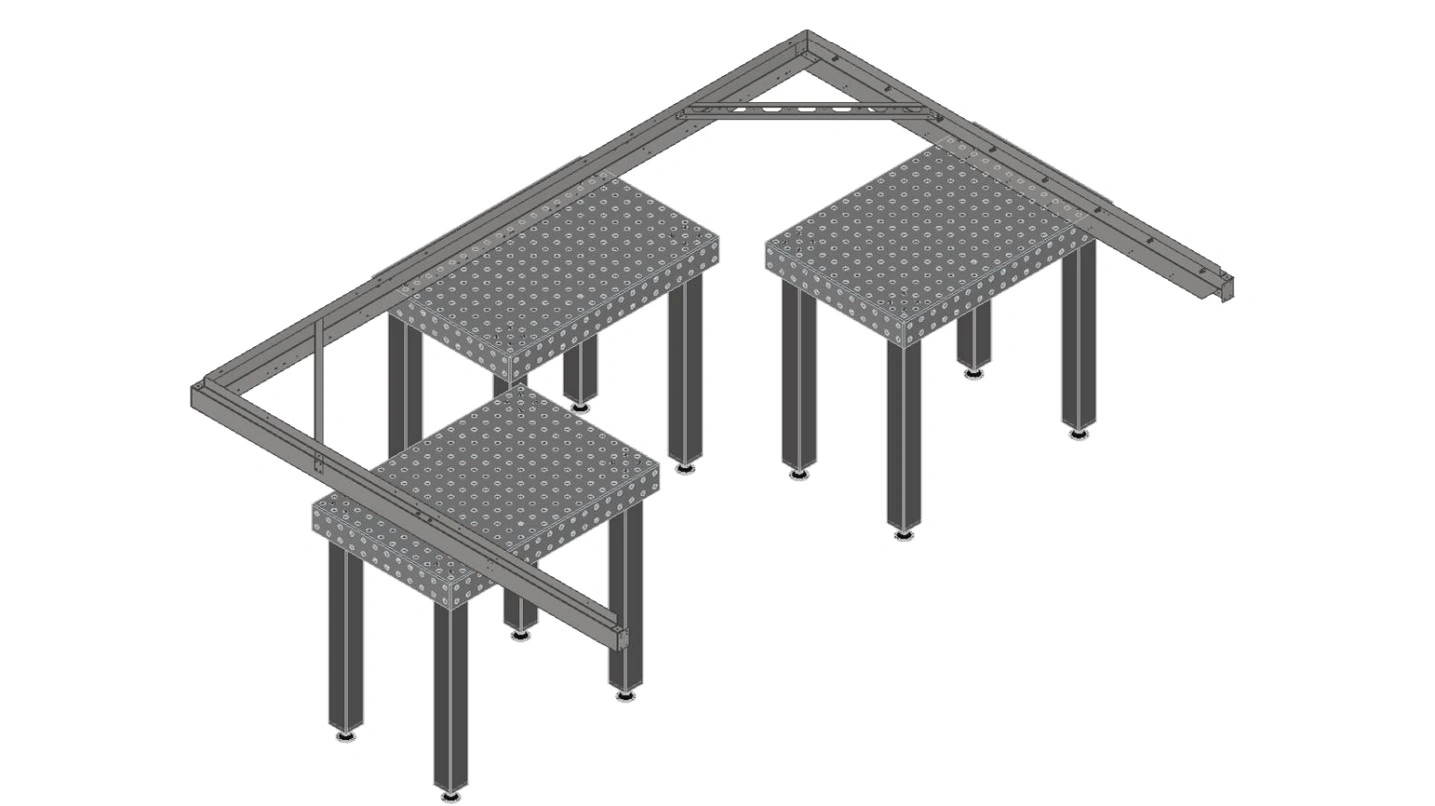
2: Roof Assembly
The second step in the assembly process is to assemble the enclosure roof.
Materials
Parts
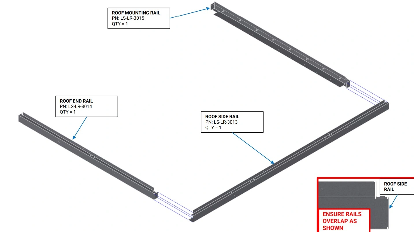
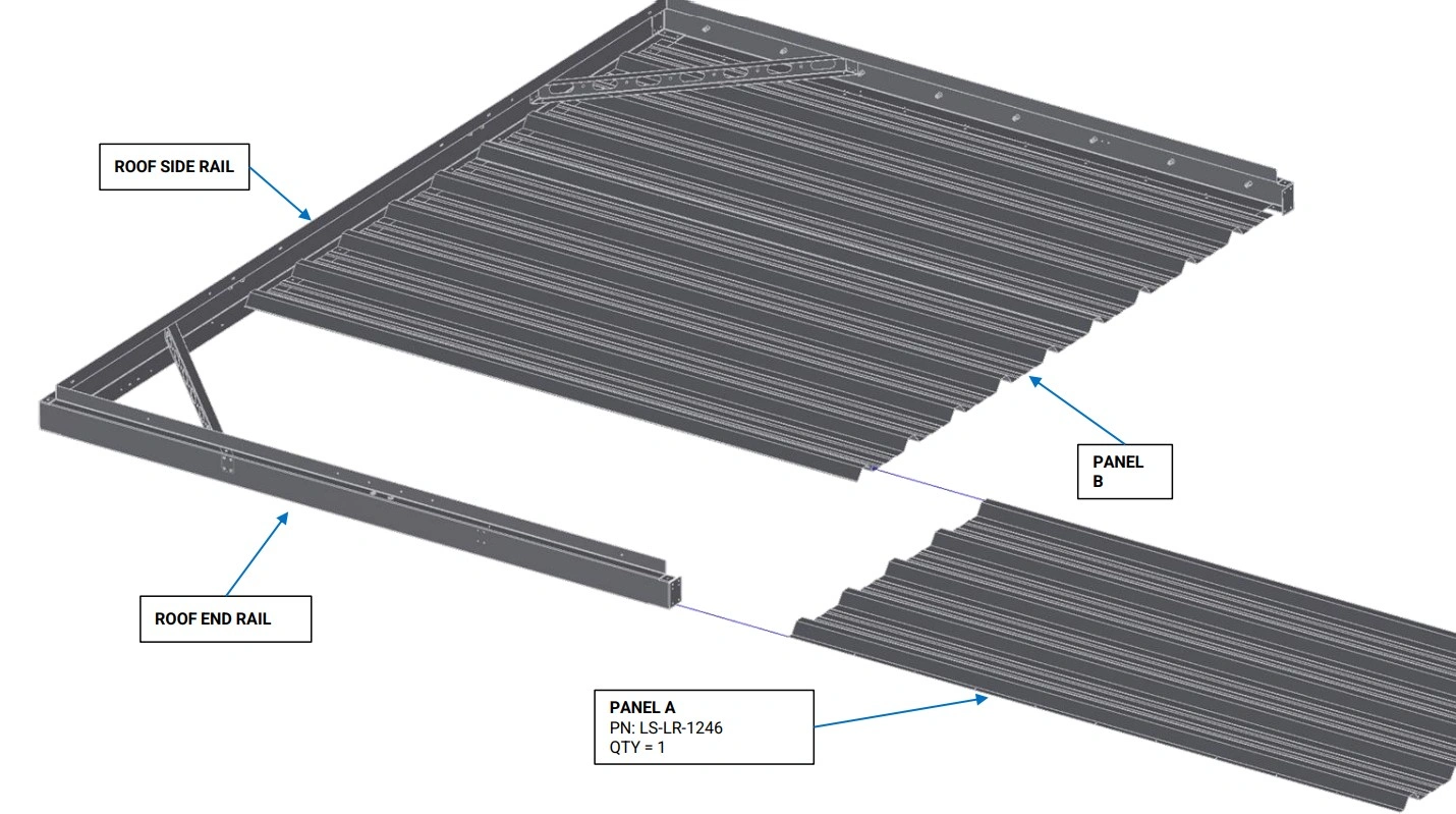
- (1) Roof End Rail
- (1) Roof Mounting Rail
- (1) Roof Side Rail
Hardware
- None
Tools
- Mallet (Optional)
Instructions
- With the vertical flange of the Roof Rails oriented upwards, slide the ends of the Roof End Rail and the Roof Mounting Rail into the C channel of the Roof Side Rail as shown. If the fitment between the Roof Rails is tight, a mallet can be used to gently tap the rails together.
- Adjust the Roof End Rail and the Roof Mounting Rail such that they are approximately perpendicular to the Roof Side Rail.
Materials
Parts
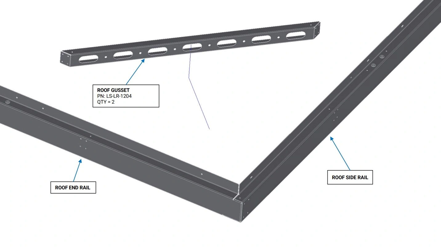
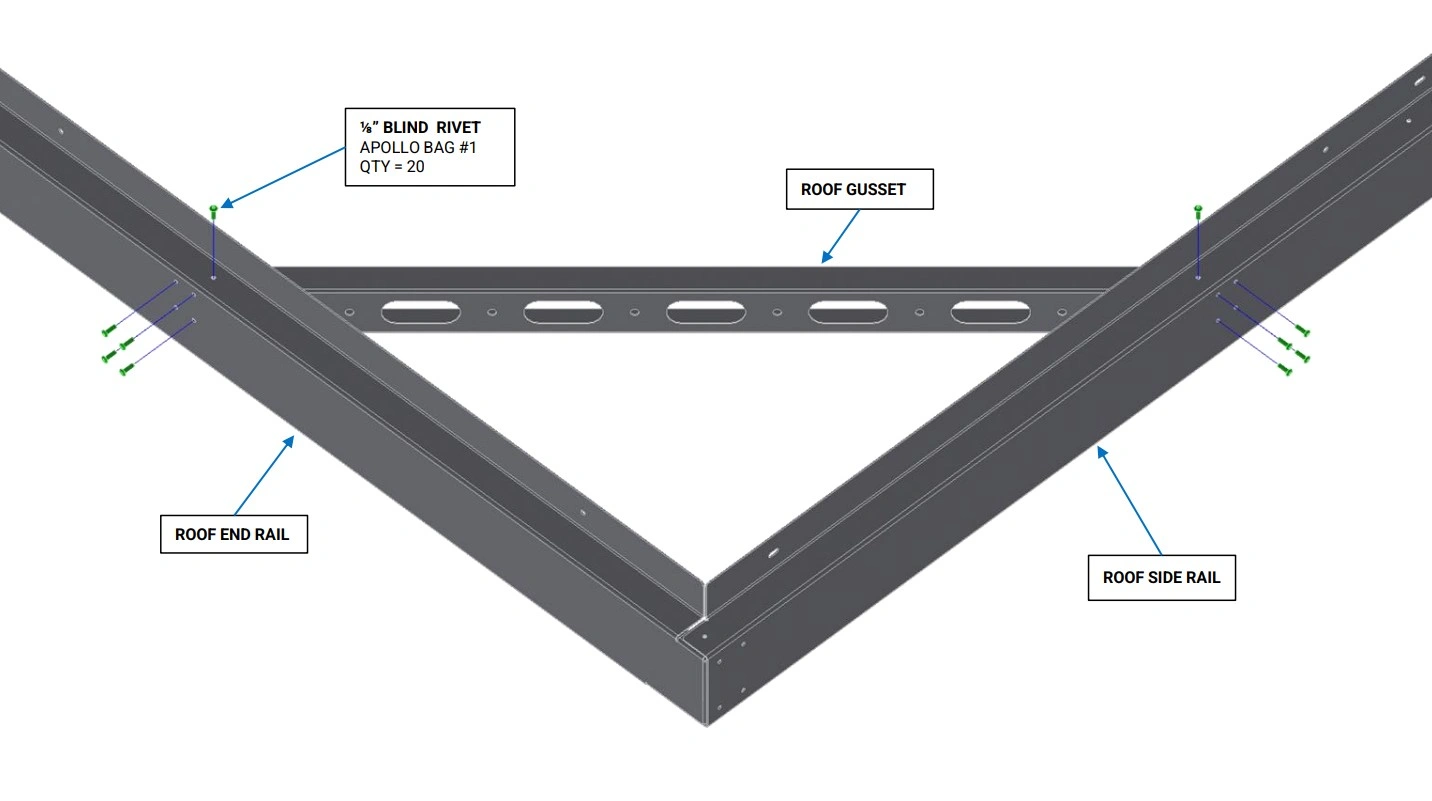
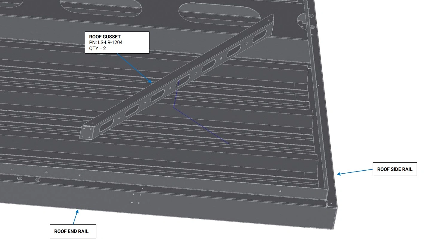
- (2) Roof Gusset
Hardware
- (20) ⅛” Blind Rivets
Tools
- (Optional) ⅛” Cleco Pins
Instructions
- Place a Roof Gusset in the corner between the Roof End Rail and Roof Side Rail as shown. Align the 8 holes on the side, and 2 holes on the top of the Roof Gusset with the corresponding holes in the Roof Rails.
- With the Roof Gusset holes aligned to the Roof Rails, Slide rivets or Cleco pins into 3-4 holes on the Roof Rails to hold the Roof Gussets in place.
- Using the another Roof Gusset, repeat step B1 and B2 for the corner between the Roof Mounting Rail and Roof Side Rail.
Materials
Parts
- None
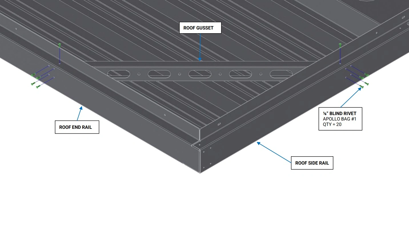
Hardware
- (20) ⅛” Blind Rivets
Tools
- Rivet Gun
Instructions
- Using the ⅛” Blind Rivets, rivet the Roof Gussets to the Roof Rails as shown.
Materials
Parts
- None
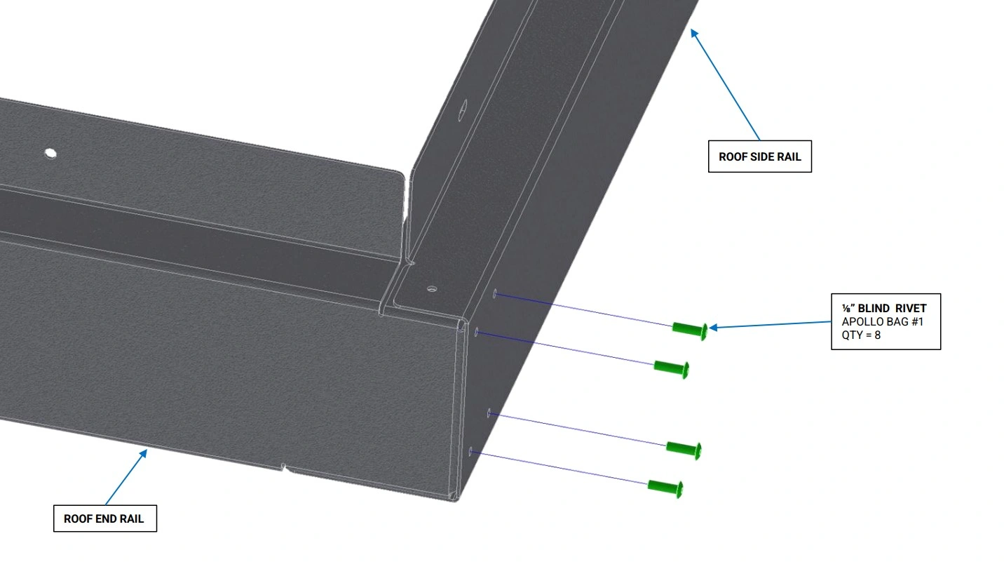
Hardware
- (8) ⅛” Blind Rivets
Tools
- Rivet Gun
Instructions
- Ensure the 8 holes on the side of the Roof Side Rail are well aligned with the 4 holes on the end of the Roof End Rail and Roof Mounting Rail.
- Using the ⅛” Blind Rivets, rivet the Roof End Rail to the Roof Side Rail as shown.
- Repeat step D2 for the Roof Mounting Rail.
Materials
Parts
- None
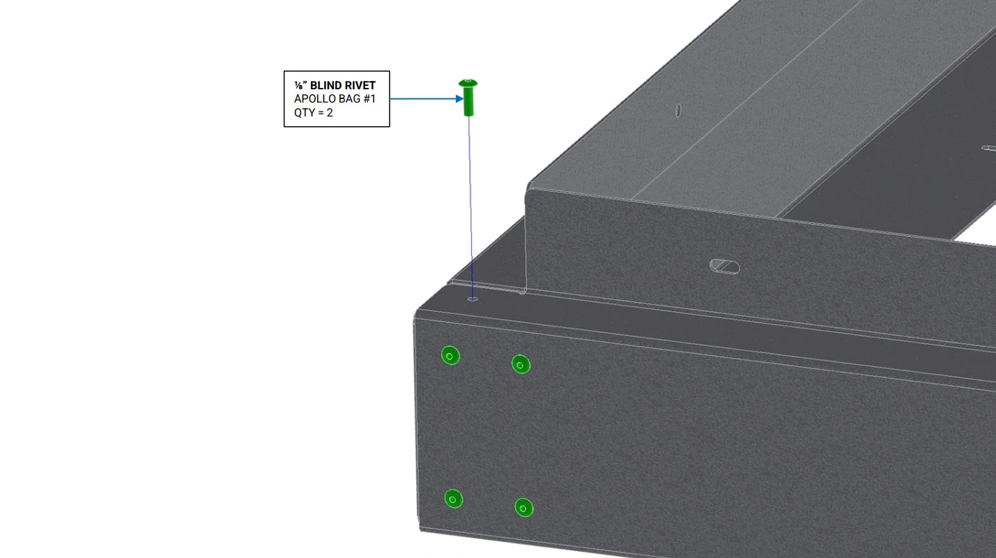
Hardware
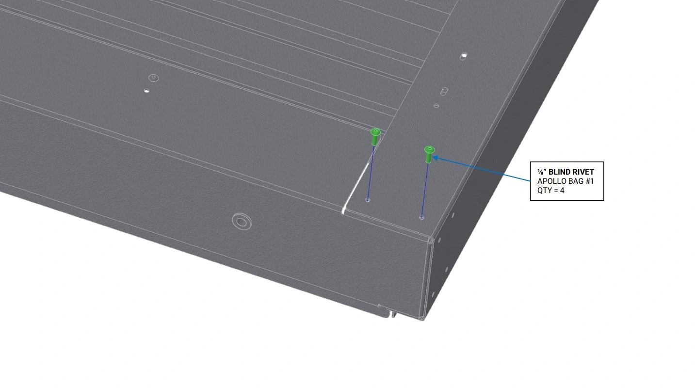
- (2) ⅛” Blind Rivets
Tools
- Rivet Gun
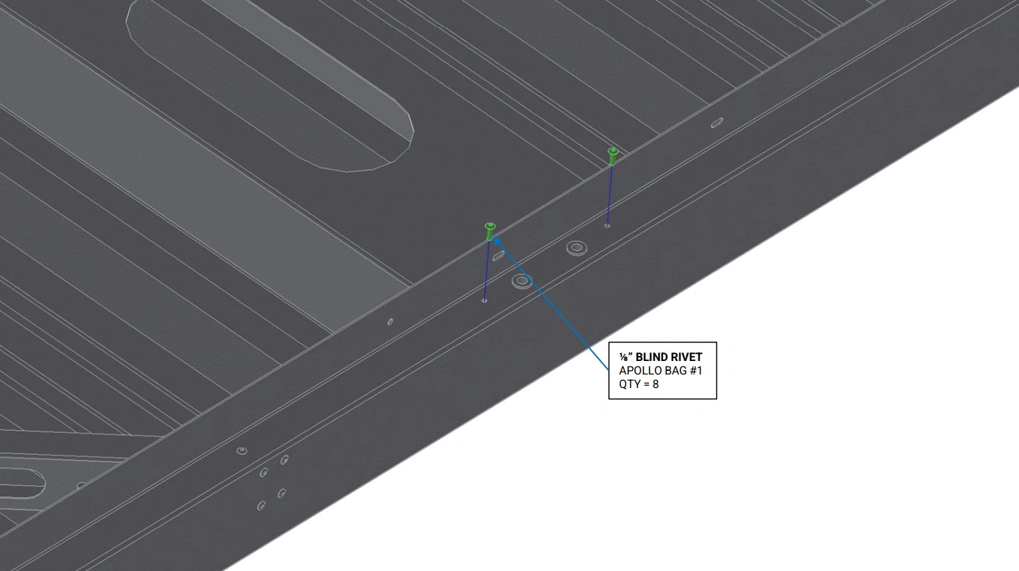
Instructions
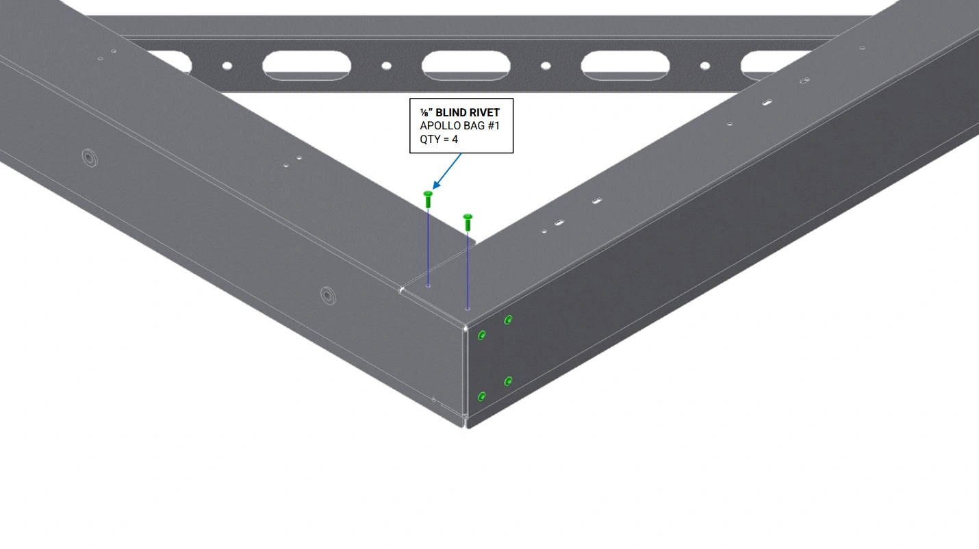
- Ensure the 2 holes on the top of the Roof Side Rail are well aligned with the holes on the top of the Roof End Rail and Roof Mounting Rail.
- Using the ⅛” Blind Rivets, rivet the Roof End Rail to the Roof Side Rail as shown.
- Repeat step E2 for the Roof Mounting Rail.
Materials
Parts
- None
Hardware
- None
Tools
- Boxes, tables or other supports
Instructions
- Place the frame with the vertical flange of the Roof Rails Facing upwards on at least 3 boxes or tables, such that there is sufficient access to the bottom of the rails for installation of rivets. It should be possible to shift the frame on its supports such that all holes in the bottom of the rails can be accessed.
Materials
Parts
- None
Hardware
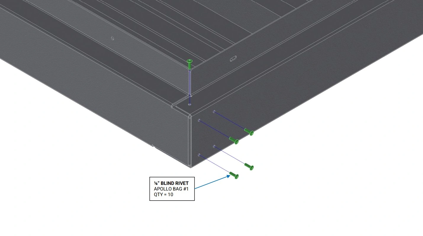
- (4) ⅛” Blind Rivets
Tools
- Rivet Gun
Instructions
- Ensure the 4 holes on the bottom of the Roof Side Rail are well aligned with the 2 holes on the bottom of the Roof End Rail and Roof Mounting Rail.
- Using the ⅛” Blind Rivets, rivet the Roof End Rail to the Roof Side Rail as shown.
- Repeat step G2 for the Roof Mounting Rail.
Materials
Parts
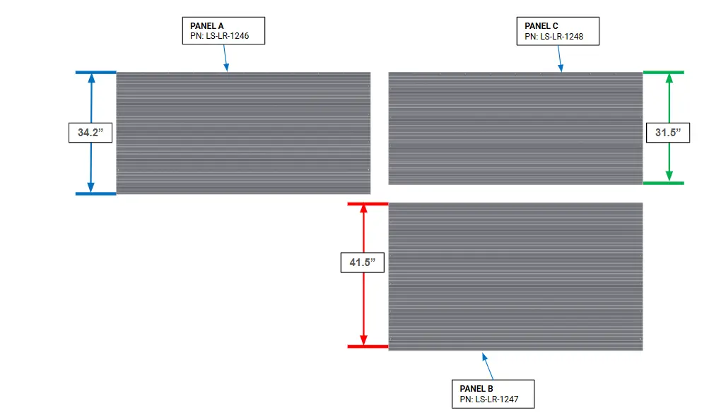
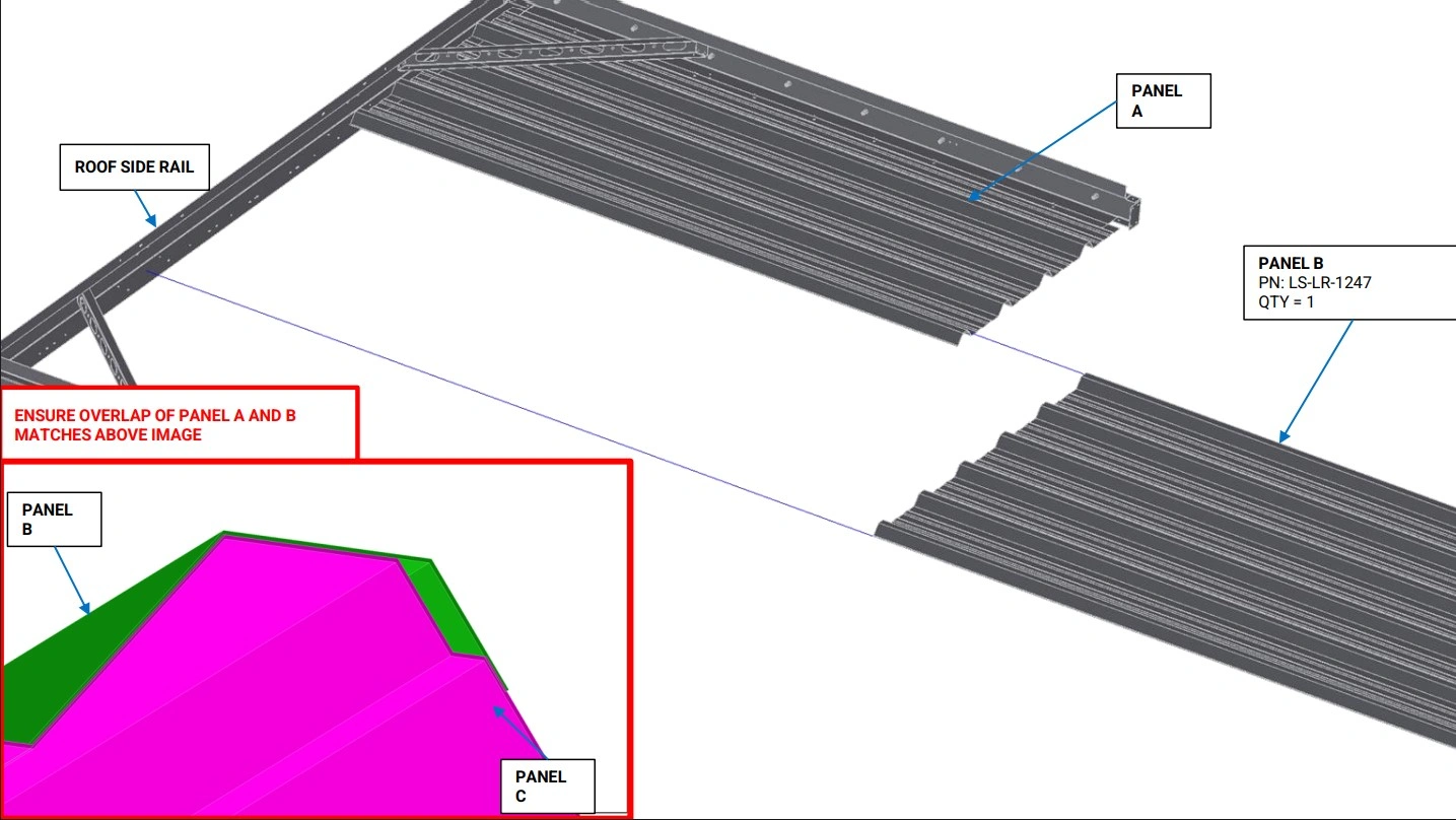
- (1) Panel A
- (1) Panel B
- (1) Panel C
Hardware
- None
Tools
- Measuring Tape or 3’+ Ruler
Instructions
- Using a measuring tape or 3’+ ruler, locate Panel A, Panel B, and Panel C with approximate lengths of 34.2”, 41.5”, and 31.5”.
Materials
Parts
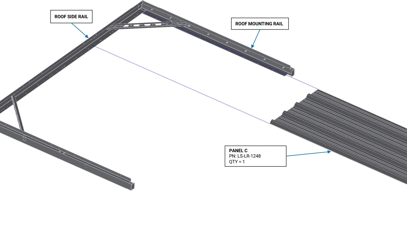
- (1) Panel C
Hardware
- None
Tools
- (Optional) Boxes, tables or other supports
Instructions
- Orient Panel C such that the rivet holes on the long side of the panel face the Roof Mounting Rail and the ribs of Panel C face upwards as shown.
- Slide Panel C along the bottom flange of the Roof Mounting Rail and onto the bottom flange of the Roof Side Rail.
- If necessary, add additional supports under Panel C to keep it in position.
Materials
Parts
- None
Hardware
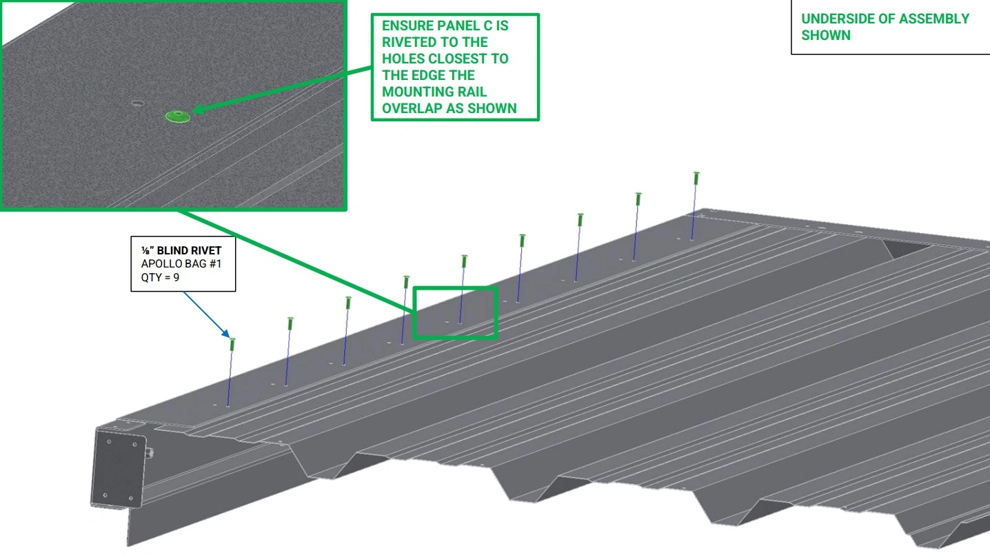
- (9) ⅛” Blind Rivet
Tools
- Rivet Gun
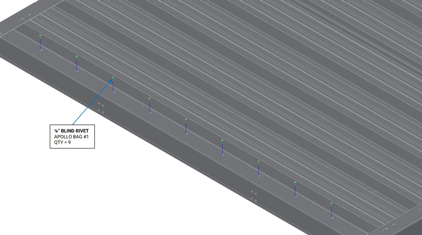
Instructions
- Ensure the rivet holes in the bottom of the Roof Mounting Rail align with the rivet holes in Panel C.
- Using the ⅛” Blind Rivets, rivet Panel C to the Roof Mounting Rail as shown.
Materials
Parts
- (1) Panel B
Hardware
- None
Tools
- (Optional) Boxes, tables or other supports
Instructions
- Orient Panel B such that the rivet holes on the short side face the Roof Side Rail and the outermost partial rib is closest to Panel C.
- Slide the outermost rib of Panel B on top of the outermost rib of Panel A. Slide Panel B onto the bottom flange of the Roof Side Rail.
- If necessary, add additional supports under Panel B to keep it in position.
Materials
Parts
- (1) Panel A
Hardware
- None
Tools
- (Optional) Boxes, tables or other supports
Instructions
- Orient Panel A such that the rivet holes on the long side face the Roof End Rail.
- Slide the outermost partial rib of Panel A on top of the partial rib of Panel B and slide Panel A along the bottom flange of the Roof End Rail and onto the bottom flange of the Roof Side Rail.
- If necessary, add additional supports under Panel A to keep it in position.
Materials
Parts
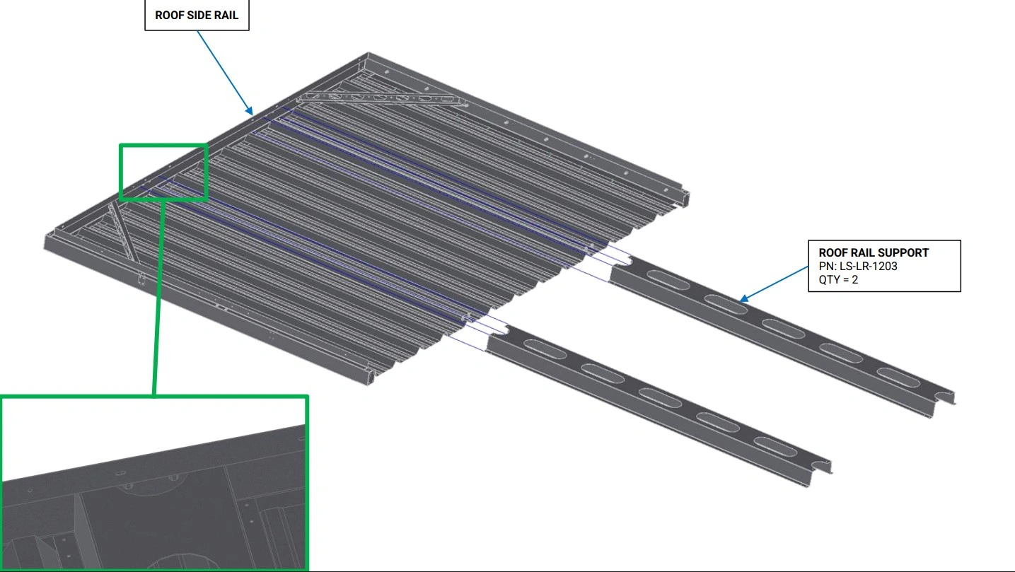
- (2) Roof Rail Support
Hardware
- None
Tools
- (Optional) Boxes, tables or other supports
Instructions
- Slide the Roof Rail Supports into the C channel of the Roof Side Rail such that the rivet nuts in the Roof Side Rail rest in the half circle cutout at the top of the Roof Rail Support and the holes on the end of the Roof Rail Support align with the corresponding holes on the Roof Side Rail.
- If necessary, add additional supports under the Roof Rail Supports to keep them in position.
Materials
Parts
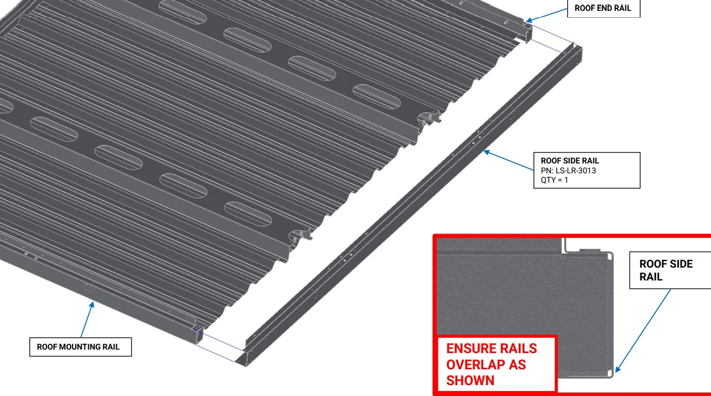
- (1) Roof Side Rail
Hardware
- None
Tools
- Mallet (Optional)
Instructions
- With the vertical flange of the Roof Rails oriented upwards, slide the end of the Roof End Rail and the Roof Mounting Rail into the C channel of the Roof Side Rail as shown. If the fitment between the Roof Rails is tight, a mallet can be used to gently tap the rails together.
Materials
Parts
- (2) Roof Gusset
Hardware
- (20) ⅛” Blind Rivets
Tools
- (Optional) ⅛” Cleco Pins
Instructions
- Place a Roof Gusset in the corner between the Roof End Rail and Roof Side Rail as shown. Align the 8 holes on the side, and 2 holes on the top of the Roof Gusset with the corresponding holes in the Roof Rails.
- With the Roof Gusset holes aligned to the Roof Rails, Slide rivets or Cleco pins into 3-4 holes on the Roof Rails to hold the Roof Gussets in place.
- Using the another Roof Gusset, repeat step O1 and O2 for the corner between the Roof Mounting Rail and Roof Side Rail.
Materials
Parts
- None
Hardware
- (20) ⅛” Blind Rivets
Tools
- Rivet Gun
Instructions
- Using the ⅛” Blind Rivets, rivet the Roof Gussets to the Roof Rails as shown.
Materials
Parts
- None
Hardware
- (4) ⅛” Blind Rivets
Tools
- Rivet Gun
Instructions
- Ensure the 4 holes on the bottom of the Roof Side Rail are well aligned with the 2 holes on the bottom of the Roof End Rail and Roof Mounting Rail.
- Using the ⅛” Blind Rivets, rivet the Roof End Rail to the Roof Side Rail as shown.
- Repeat step Q2 for the Roof Mounting Rail.
Materials
Parts
- None
Hardware
- (10) ⅛” Blind Rivets
Tools
- Rivet Gun
Instructions
- Ensure the 10 holes on the side and top of the Roof Side Rail are well aligned with the holes on the top of the Roof End Rail and Roof Mounting Rail.
- Using the ⅛” Blind Rivets, rivet the Roof End Rail to the Roof Side Rail as shown.
- Repeat step R2 for the Roof Mounting Rail.
Materials
Parts
- None
Hardware
- (8) ⅛” Blind Rivets
Tools
- Rivet Gun
Instructions
- Ensure the top holes on the Roof Rail Supports are aligned with the corresponding holes in the Roof Side Rails.
- Using the ⅛” Blind Rivets, rivet both Roof Rail Supports to the Roof Side Rails as shown.
Materials
Parts
- None
Hardware
- (9) ⅛” Blind Rivet
Tools
- Rivet Gun
Instructions
- Ensure the rivet slots in the bottom of the Roof End Rail align with the rivet holes in Panel A.
- Using the ⅛” Blind Rivets, rivet Panel A to the Roof End Rail as shown.
Materials
Parts
- None
Hardware
- None
Tools
- Drill
- ⅛” Drill Bit
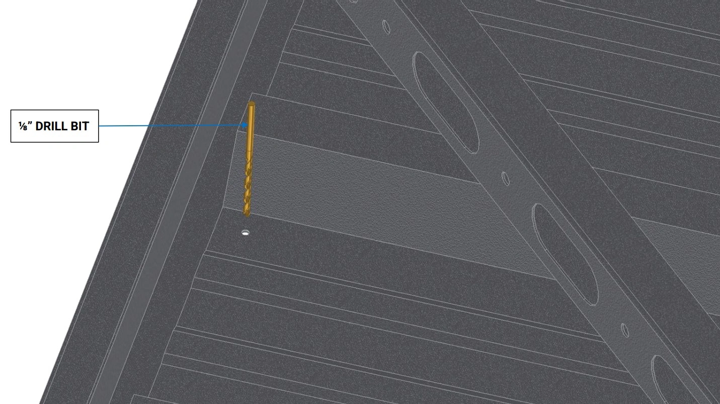
Instructions
- Starting at the top of Panel C, use a ⅛” drill bit to bore a hole through the Roof Side Rails.
- Repeat this step for the remaining 17 pilot holes in Panels A, B and C to allow the panels to be riveted to the Roof Side Rails.
Materials
Parts
- None
Hardware
- (34) ⅛” Blind Rivet
Tools
- Rivet Gun
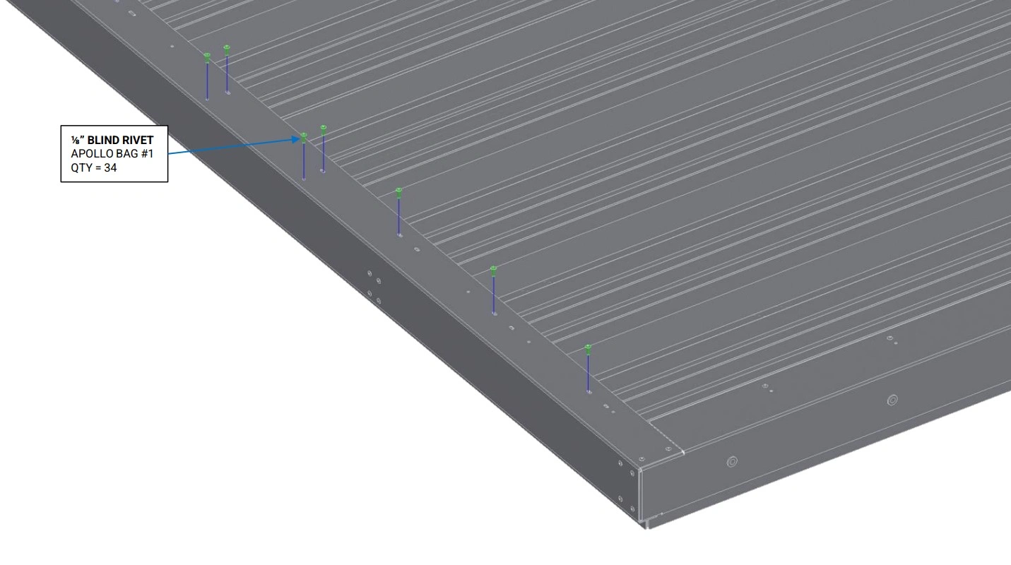
Instructions
- Ensure the rivet slots in the bottom of the Roof Side Rails align with the drilled rivet holes in Panel A, Panel B, and Panel C, and the rivet holes in the Roof Rail Supports.
- Using the ⅛” Blind Rivets, rivet Panels A, B and C to the Roof Side Rail and Roof Rail Support as shown.
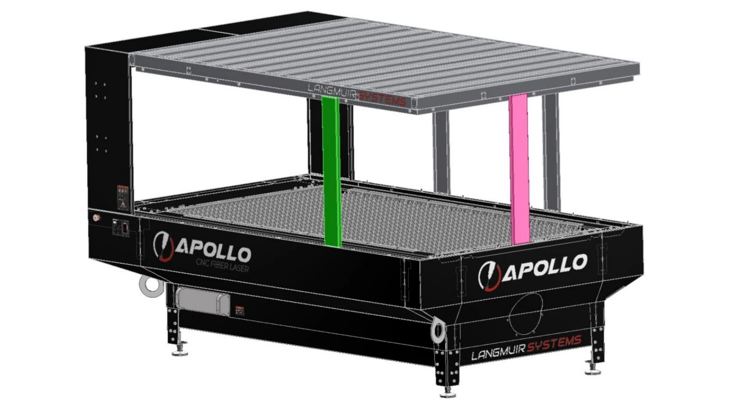
3: Roof Installation
The next step in the assembly process is to install the roof assembly.
Materials
Parts
- (4) Roof Stanchion
Hardware
- (8) BHCS, M6 X 1 X 16mm
Tools
- 4mm Hex Key
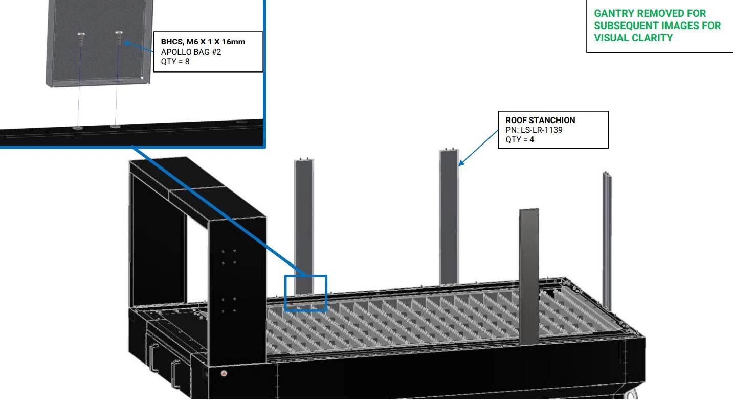
Instructions
- Using the M6 button head screws, bolt the Roof Stanchions to the rivet nuts on the lower enclosure as shown.
Materials
Parts
- (1) Roof Assembly
Hardware
- (16) BHCS, M6 X 1 X 16mm
Tools
- 4mm Hex Key
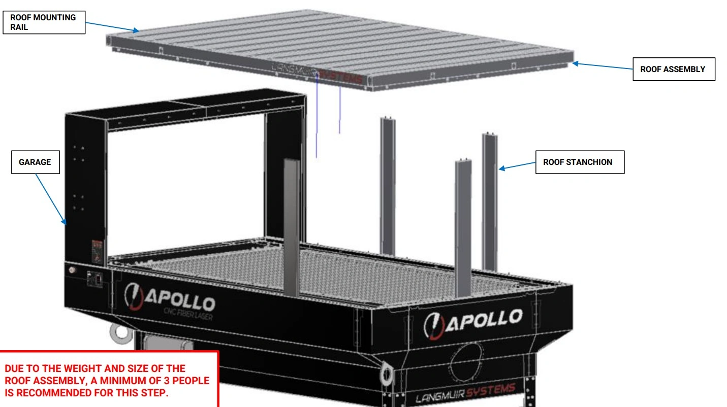
Instructions
- Before performing the following steps ensure you have a secure method of lifting, and holding the Roof Assembly for installation. To manually lift and install the Roof Assembly, a minimum of 3 people is recommended. Once the roof is in place, it will need to be bolted to the stanchions and garage while continuing to be held in place. As such, it is recommended to have the required 14x M6 screws and 4mm Hex Key set aside for immediate installation in instruction set C and D.
- Orient the Roof Assembly with the vertical flange facing down and the horizontal rivet nuts in the Roof Mounting Rail facing towards the Garage and lower the Roof Assembly onto the four Roof Stanchions as shown.
Materials
Parts
- (1) Roof Assembly
Hardware
- (6) BHCS, M6 X 1 X 16mm
Tools
- 4mm Hex Key
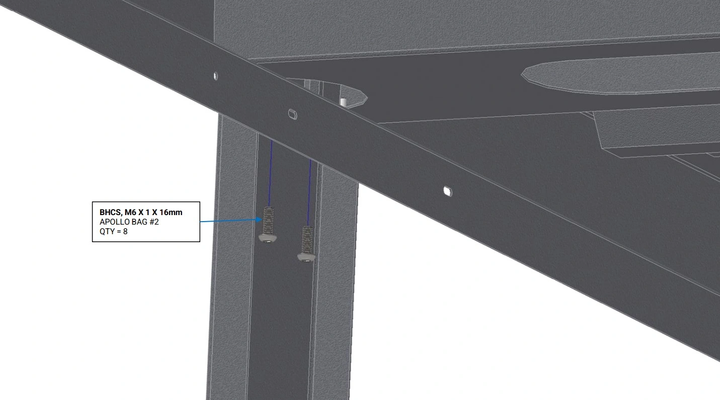
Instructions
- While continuing to support the Roof Assembly, align the slots in the top of the Roof Stanchions, with the corresponding rivet nuts in the Roof Assembly.
- Using the M6 button head screws, loosely bolt each of the four Roof Stanchions to the Roof Assembly. These bolts will be tightened later in section 6 step D3.
Materials
Parts
- (1) Roof Assembly
Hardware
- (8) BHCS, M6 X 1 X 16mm
Tools
- 4mm Hex Key
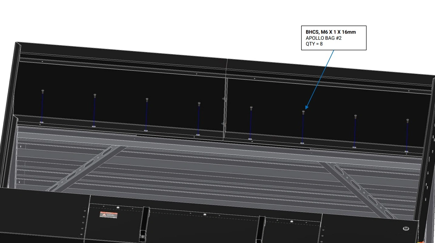
Instructions
- While continuing to support the Roof Assembly, align the slots in the top of the Garage, with the corresponding rivet nuts in the Roof Assembly.
- Using the M6 button head screws, loosely bolt Garage to the Roof Assembly. These bolts will be tightened later in section 6 step C5.
Materials
Parts
- None
Hardware
- None
Tools
- 4mm Hex Key
Instructions
NOTE
Three (3) stanchions must be used to support the roof in addition to being secured to the garage.
- Remove extra stanchion provided for assembly help.
- Remove the stanchion colored green for 8 foot loading access. The pink stanchion must be used for supporting the roof. This is the most common setup for material loading.
- If 4 foot loading is desired, least common option, remove the pink stanchion while the green stanchion will remain to support the roof.
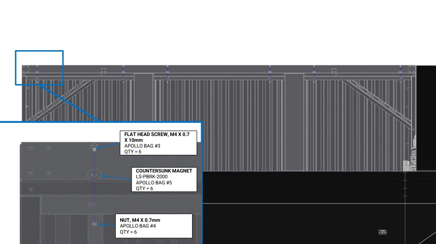
4: Door Installation
The next step in the assembly process is to install the doors.
Materials
Parts
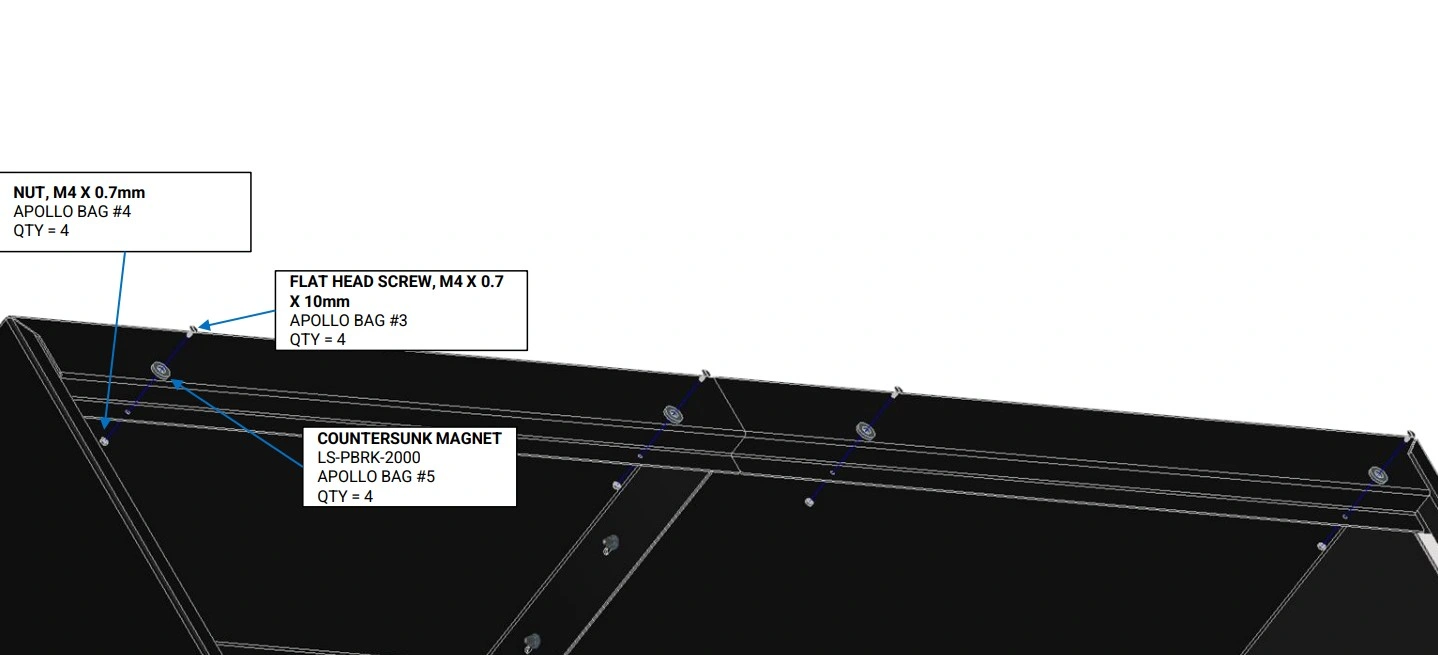
- (6) Countersunk Magnet
Hardware
- (6) FLAT HEAD SCREW, M4 X 0.7 X 10mm
- (6) NUT, M4 X 0.7mm
Tools
- 2.5mm Allen Key
- 7mm Combination Wrench
Instructions
- Bolt the Countersunk Magnets onto the rear flange of the Roof Assembly as shown. Hold the nut with one hand or 7mm combination wrench and tighten the flat head screw until the assembly is just hand tight. Excessive tightening can cause the Countersunk Magnet to crack.
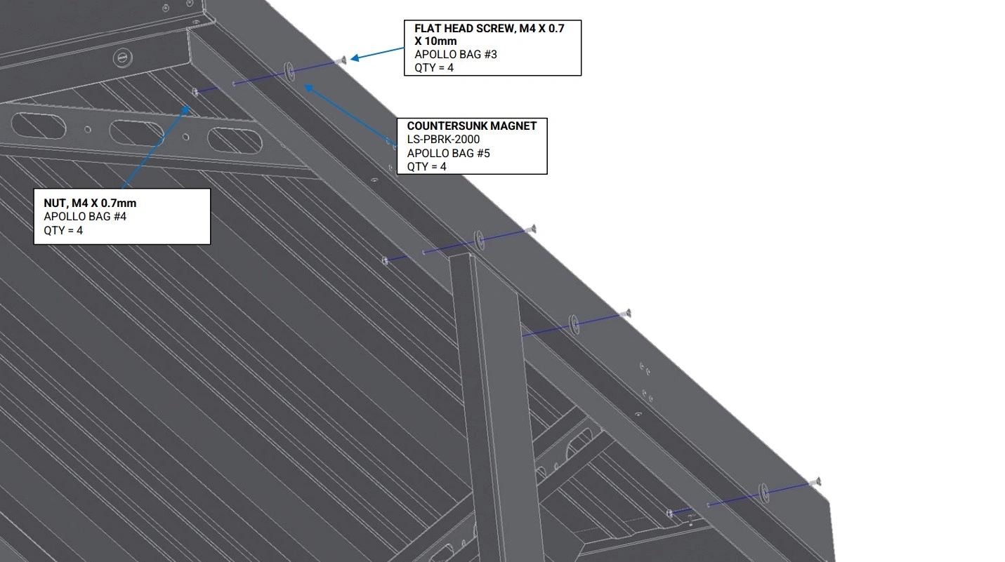
Materials
Parts
- (4) Countersunk Magnet
Hardware
- (4) FLAT HEAD SCREW, M4 X 0.7 X 10mm
- (4) NUT, M4 X 0.7mm
Tools
- 2.5mm Allen Key
- 7mm Combination Wrench
Instructions
- Bolt the Countersunk Magnets onto the side flange of the Roof Assembly as shown. Hold the nut with one hand or 7mm combination and tighten the flat head screw until the assembly is just hand tight. Excessive tightening can cause the Countersunk Magnet to crack.
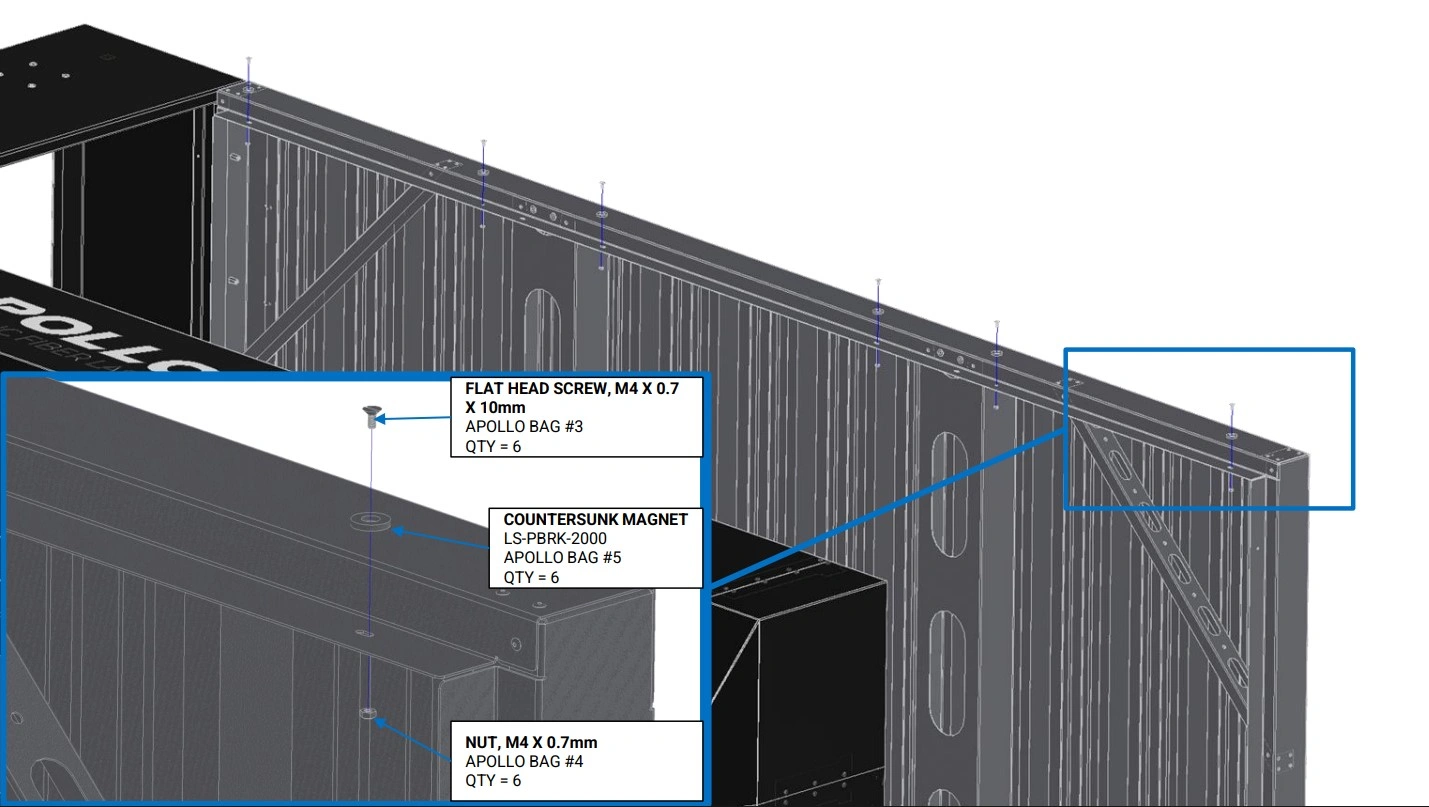
Materials
Parts
- (6) Countersunk Magnet
Hardware
- (6) FLAT HEAD SCREW, M4 X 0.7 X 10mm
- (6) NUT, M4 X 0.7mm
Tools
- 2.5mm Allen Key
- 7mm Combination Wrenchr
Instructions
- Bolt the Countersunk Magnets onto the front flange of the Roof Assembly as shown. Hold the nut with one hand or 7mm combination wrench and tighten the flat head screw until the assembly is just hand tight. Excessive tightening can cause the Countersunk Magnet to crack.
Materials
Parts
- (4) Countersunk Magnet
Hardware
- (4) FLAT HEAD SCREW, M4 X 0.7 X 10mm
- (4) NUT, M4 X 0.7mm
Tools
- 2.5mm Allen Key
- 7mm Combination Wrench
Instructions
- Bolt the Countersunk Magnets onto the front flange of the Garage as shown. Hold the nut with one hand or 7mm combination wrench and tighten the flat head screw until the assembly is just hand tight. Excessive tightening can cause the Countersunk Magnet to crack.
Materials
Parts
- None
Hardware
- None
Tools
- M4 Hex Key
Instructions
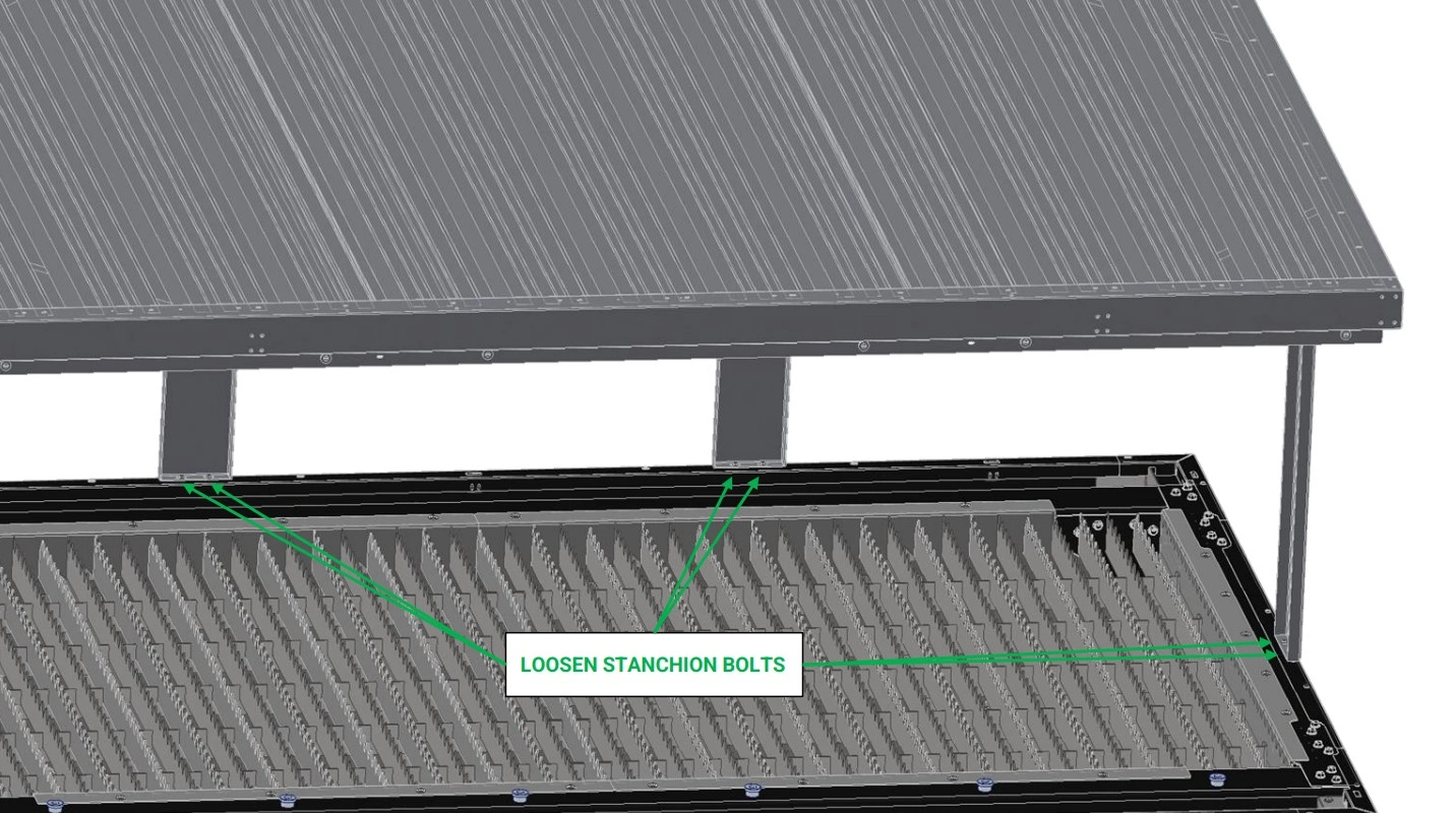
- Loosen the two M6 screws at the base of each Roof Stanchion.
- Ensure the M6 screws securing the the Roof Stanchions to the Roof Assembly and securing the Garage to the Roof Assembly are also still loose( about a quarter turn from hand tight) from Section 4.
Materials
Parts
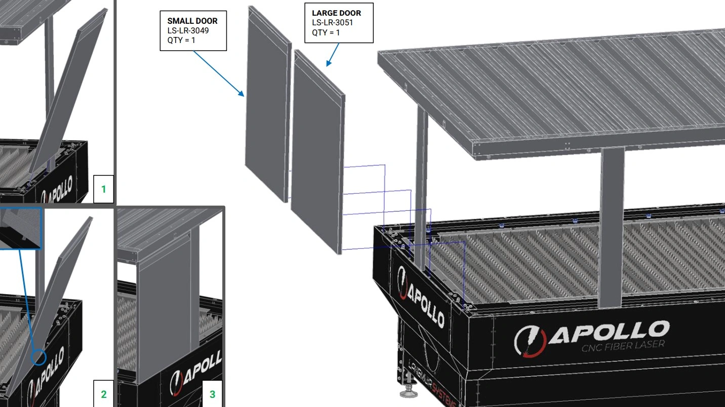
- (1) Small Door
- (1) Large Door
Hardware
- None
Tools
- Measuring Tape or 3’+ Ruler
Instructions
- Use a measuring tape or ruler to locate the Small Door, with a width of approximately 30”.
- Grip the sides of the Small Door and orient it vertically, with the rivet nuts facing down and the door handle facing towards you.
- Tilt the Small Door slightly, such that rivets nuts move away from you.
- Align the rivet nuts with the slots on the left hand side of the short side of the enclosure.
- Insert the rivet nuts into the enclosure slots, adjust your grip to hold the door by the recessed handle, and slowly tilt the door back to vertical, until the magnets snap it firmly in place.
- If necessary, slide the far side Roof Stanchion left or right to allow for installation of the Small Door with minimum gaps.
- Repeat steps F1-F6 for the Large Door, which should measure 36” in width.
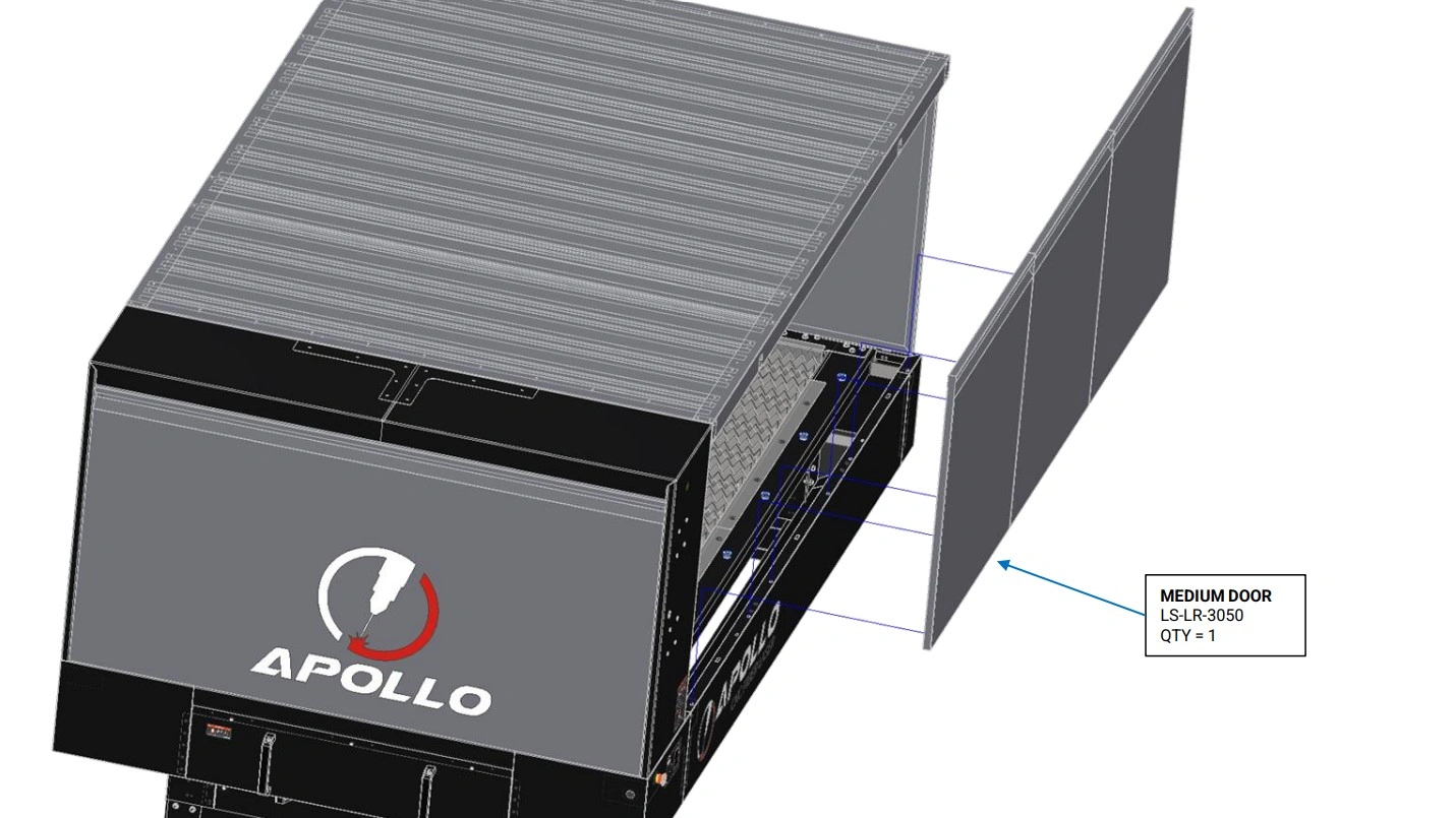
Materials
Parts
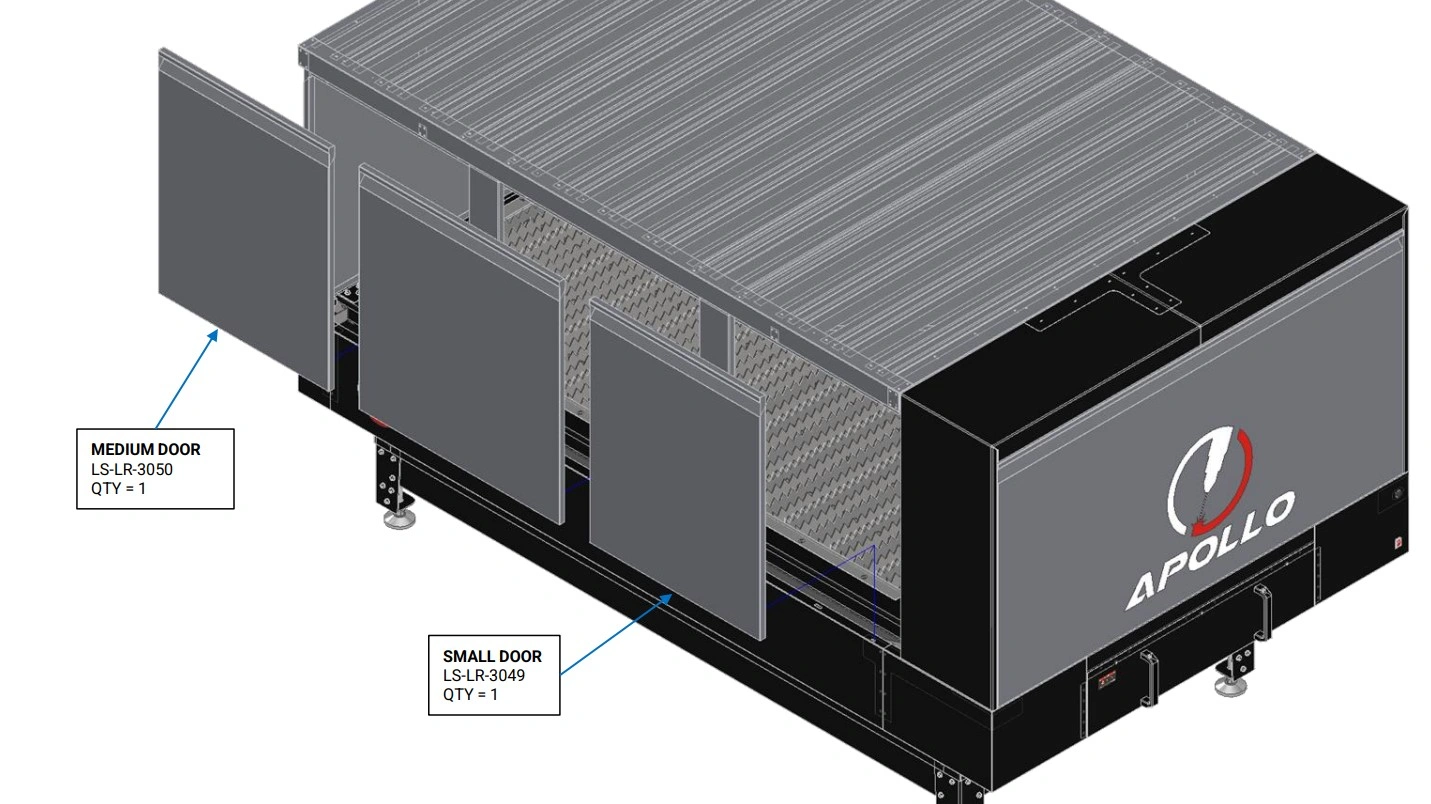
- (1) Small Door
- (2) Medium Door
Hardware
- None
Tools
- Measuring Tape or 3’+ Ruler
Instructions
- Use a measuring tape or ruler to locate one Small Door, with a width of approximately 30”, and two Medium Doors, with a width of approximately 35.25”.
- Install the Medium and Small Doors onto the rear side of the enclosure, aligning the enclosure slots and door positioning rivet nuts as shown in Steps F1-F5.
- Adjust the Roof Stanchions left and right as necessary to ensure all doors fit with minimum gaps.
Materials
Parts
- (3) Medium Door
Hardware
- None
Tools
- Measuring Tape or 3’+ Ruler
Instructions
- Use a measuring tape or ruler to locate three Medium Doors, with a width of approximately 35.25”.
- Install the Medium Doors onto the front side of the enclosure, aligning the enclosure slots and door positioning rivet nuts as shown in Steps F1-F5.
- Adjust the Roof Stanchions as necessary to ensure all doors fit with minimum gaps.
Materials
Parts
- (1) Garage Door
Hardware
- None
Tools
- None
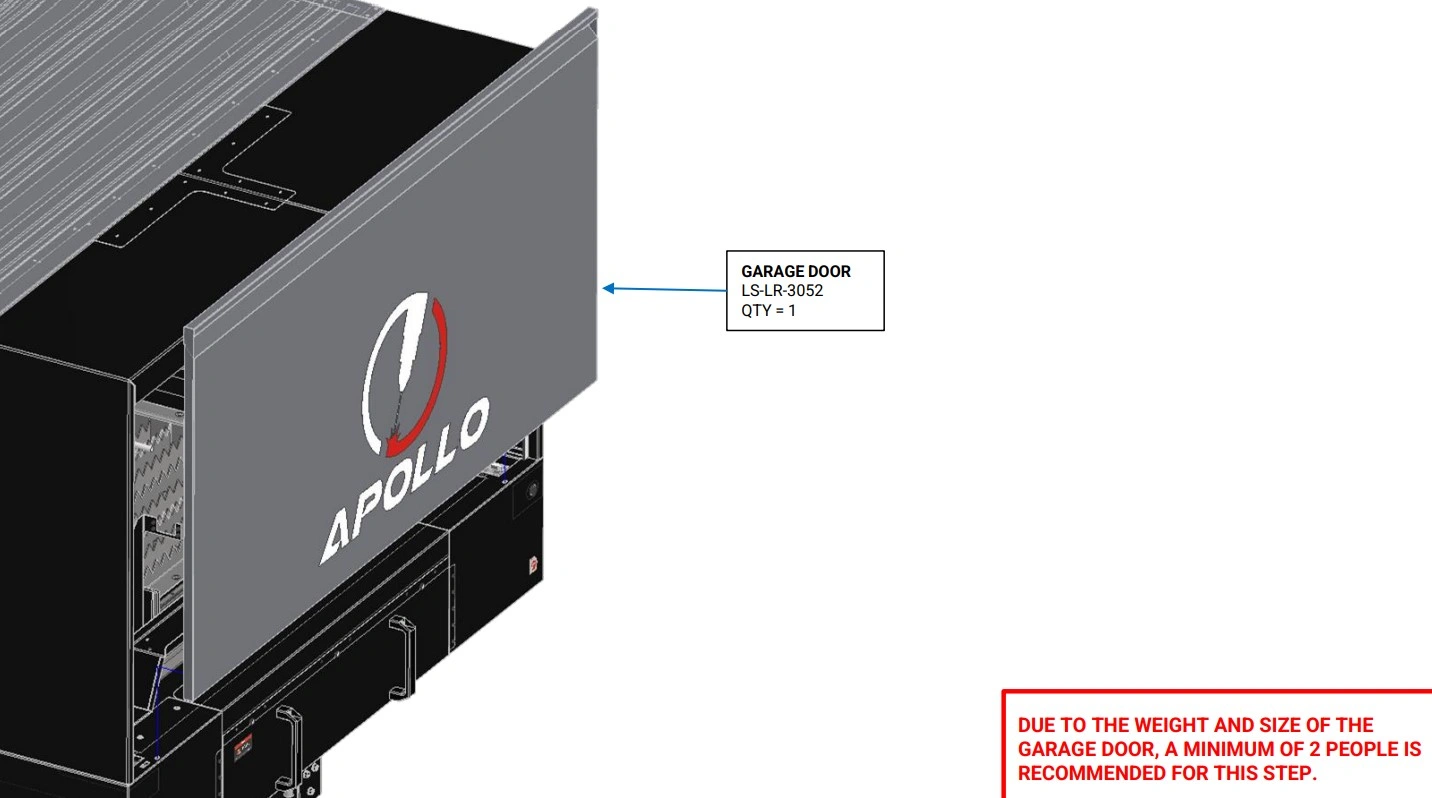
Instructions
- With the help of a second person, install the Garage doors onto the side of the enclosure, aligning the enclosure slots and door positioning rivet nuts as shown in Steps F1-F5.
5: Square Enclosure
The next step in the assembly process is to adjust the square of the enclosure and remove any large panel gaps.
Materials
Parts
- None
Hardware
- None
Tools
- 4mm Hex Key
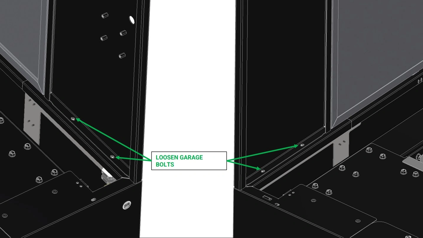
Instructions
- Loosen the 4 bolts securing the Garage to the Lower Enclosure.
Materials
Parts
- None
Hardware
- None
Tools
- 4mm Hex Key
- 3’+ Ruler, Level, or Straight Edge
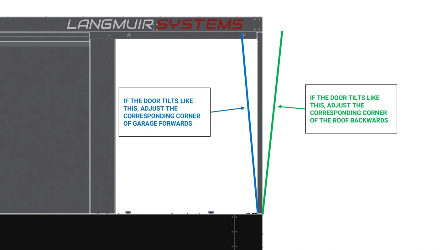
Instructions
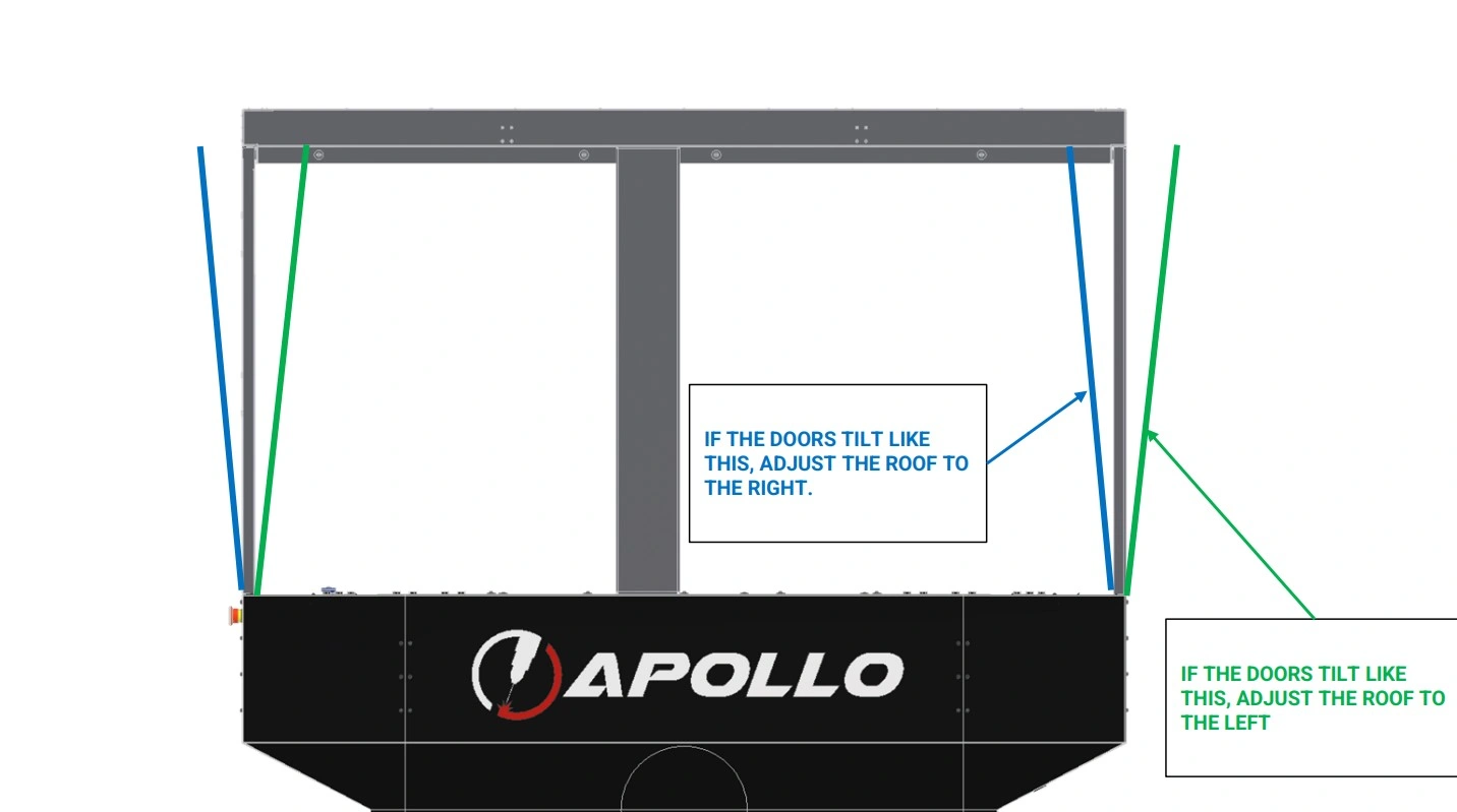
- With the Small and Large Doors installed at the end of the enclosure, rest the lower third of the straight edge against the side of the Lower Enclosure. Observe how the gap between the straight edge and the Small Door changes as you move from the base of the door upwards and use this to determine if the door is tilted outwards or inwards.
- Correct any tilt in the Small Door by shifting the closest corner of the roof forward or backward as shown above.
- Re-check the angle of the Small Door and repeat step B2 until the near edge of the door is satisfactorily square.
- Repeat steps B1-B3 for the Large Door and it’s closest roof corner.
- Tighten the 4 M6 screws securing the Garage to the Lower Enclosure.
Materials
Parts
- None
Hardware
- None
Tools
- 4mm Hex Key
- 3’+ Ruler, Level, or Straight Edge
Instructions
- With the Medium Doors installed in the front and back of the enclosure, rest the lower third of the straight edge against the front of the Lower Enclosure. Observe how the gap between the straight edge and the Medium Door changes as you move from the base of the door upwards and use this to determine if the door is tilted outwards or inwards.
- Repeat step C1 with the Medium Doors installed in the back of the enclosure.
- Correct any tilt in the Medium Doors by shifting the roof as shown above.
- Re-check the angle of the Medium Doors and repeat step C3 until the doors are satisfactorily square.
- Tighten the eight M6 screws securing the Roof Assembly to the Garage.
Materials
Parts
- None
Hardware
- None
Tools
- 4mm Hex Key
Instructions
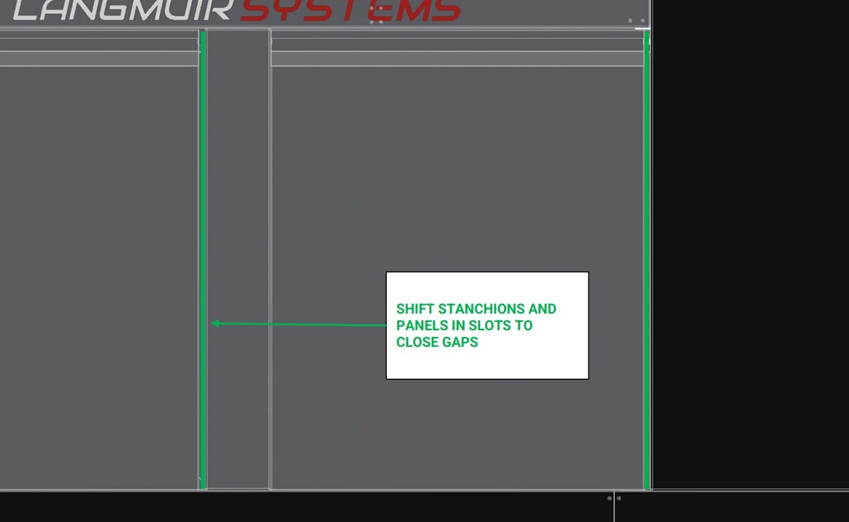
- With all Doors installed, walk around the enclosure and observe any significant gaps between the Doors, Roof Stanchions and Garage.
- Shift the Doors and Roof Stanchions as necessary to close any gaps.
- Tighten the twelve M6 screws securing the Roof Stanchions to the Lower Enclosure and Roof Assembly.
- Verify all doors have minimal to no gap and make any final, necessary adjustments. This completes the enclosure installation.
6: Mount The Monitor
The next step in the assembly process is to mount the monitor.
Materials
Parts
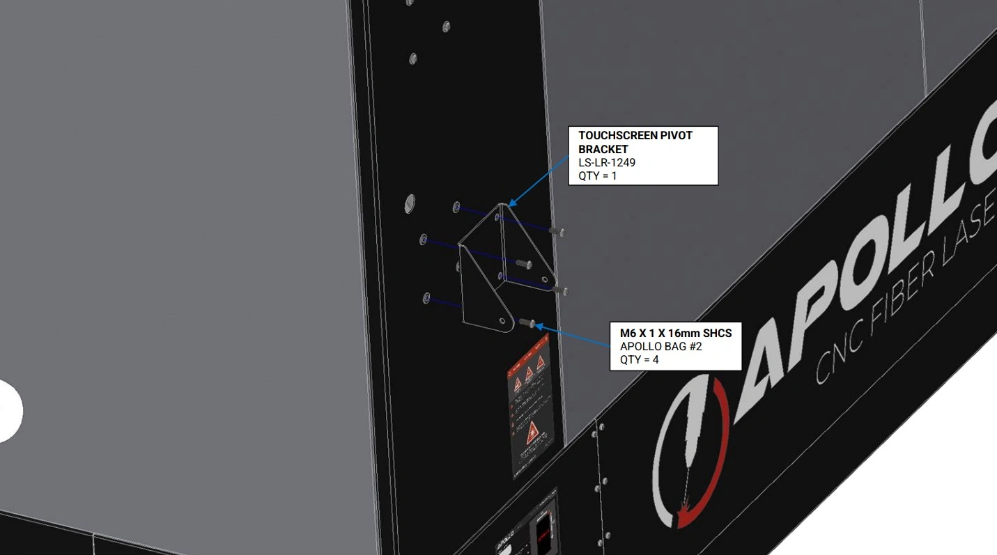
- (1) Touchscreen Pivot Bracket
Hardware
- (8) M6 x 1 x 16mm SHCS
Tools
- 4mm Hex Key
Instructions
- Locate the Touchscreen Pivot Bracket that came with your machine.
- Using the hardware shown, secure the pivot bracket to the enclosure’s rivet nuts located above the monitor that came standard with your Apollo.
- Using 4 button head cap screws, install into the unused rivet nuts to cover the enclosure holes.
Materials
Parts
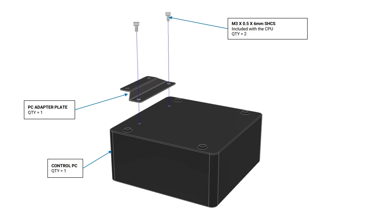
- (1) PC Adapter Plate
- (1) Control PC
Hardware
- (2) M3 x 0.5 x 6mm SHCS
Tools
- 2.5 mm Hex Key
Instructions
- Locate the PC Adapter Plate and the Control PC that came with your machine.
- Using the M3 Socket Head Cap Screws, attach the Control PC to the PC Adapter Plate as shown.
Materials
Parts
- (1) Touchscreen Vesa Mount
- (1) Control PC
Hardware
- (2) M3 x 0.5 x 6mm SHCS
- (2) M3 x 0.5 Hex Nut
Tools
- 2.5mm Hex Key
- 5.5mm Combination Wrench or Nut Driver
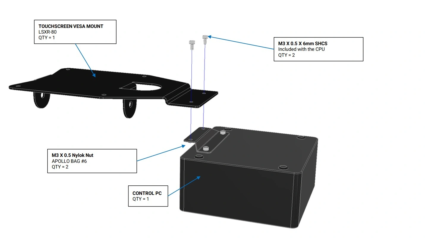
Instructions
- Using the M3 Socket Head Cap Screws and nuts , attach the Control PC to the Touchscreen Vesa Mount as shown.
Materials
Parts
- (1) 21.5” Touchscreen
Hardware
- (4) M4 x 0.7 x 6mm SHCS
Tools
- 3 mm Hex Key
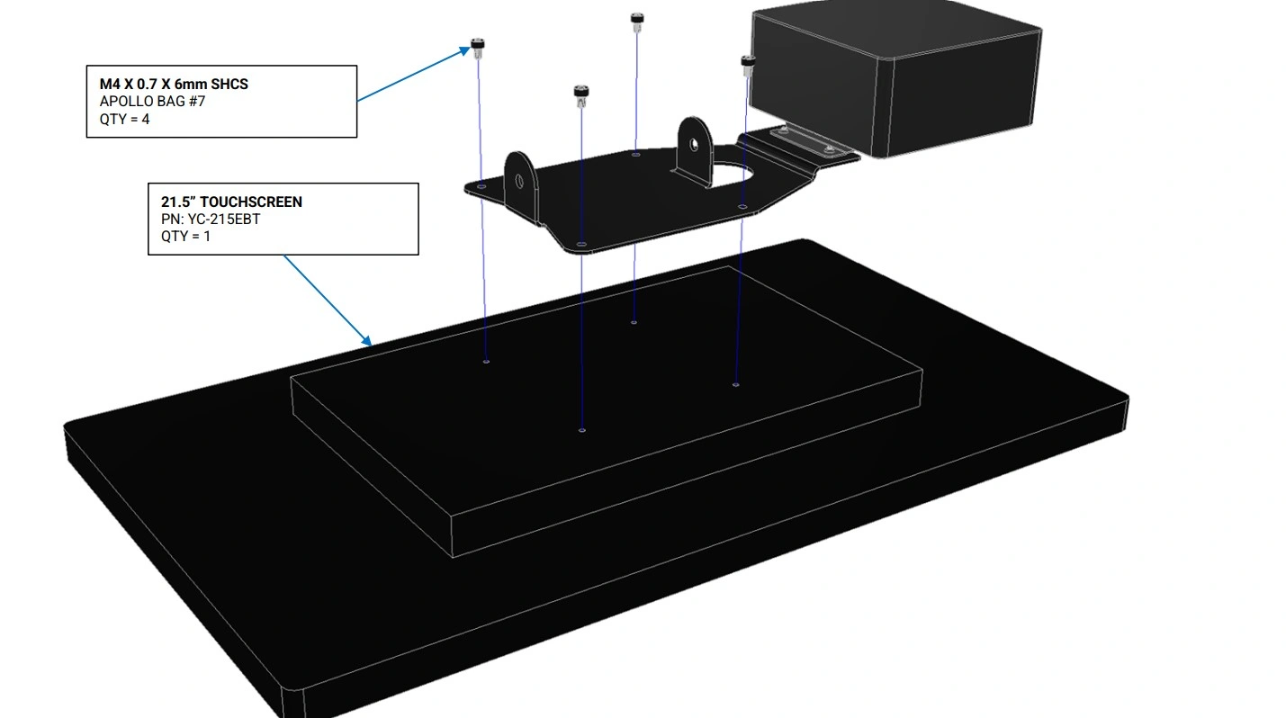
Instructions
- Locate the 21.5” Touchscreen and the Control PC that came with your machine.
- Using the hardware shown, attach the 21.5” Touchscreen to the Touchscreen Vesa Mount as shown.
Materials
Parts
- None
Hardware
- (2) M6 x 1 x 16mm SHCS
- (2) M6 Washer
- (2) M6 x 1 Serrated Flange Nut
Tools
- 4 mm Hex Key
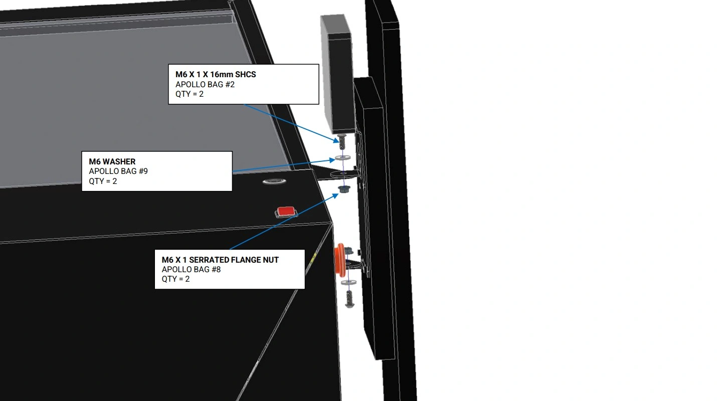
Instructions
- Using the hardware shown, attach the Touchscreen Assembly to the Touchscreen Pivot Bracket as shown. Leave the bolts only hand tight to allow for adjustment of the Touchscreen Assembly.
- Adjust the Touchscreen Assembly to its desired angle and tighten the bolts to lock it in place.
Materials
Parts
- (1) USB-A to USB-A Cable
- (1) HDMI to HDMI Cable
Hardware
- None
Tools
- None
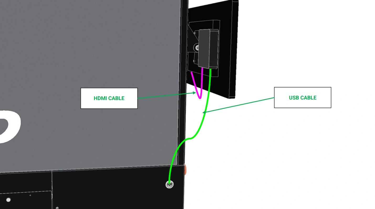
Instructions
- Using the panel mount interconnect shown, plug in one side of the USB-A to USB-A cable (GREEN) into the interconnect and the other side into the Control PC attached to the lower monitor bracket.
- Using the provided HDMI to HDMI cord (PINK), connect the Control PC to the second monitor above.
7: Assemble the Part Retrieval Cart
The next step in the assembly process is to assemble the cart.
Materials
Parts
- (2) Cart, End
- (2) Cart, Base
Hardware
- (6) ⅛” Blind Rivets
Tools
- Rivet Gun
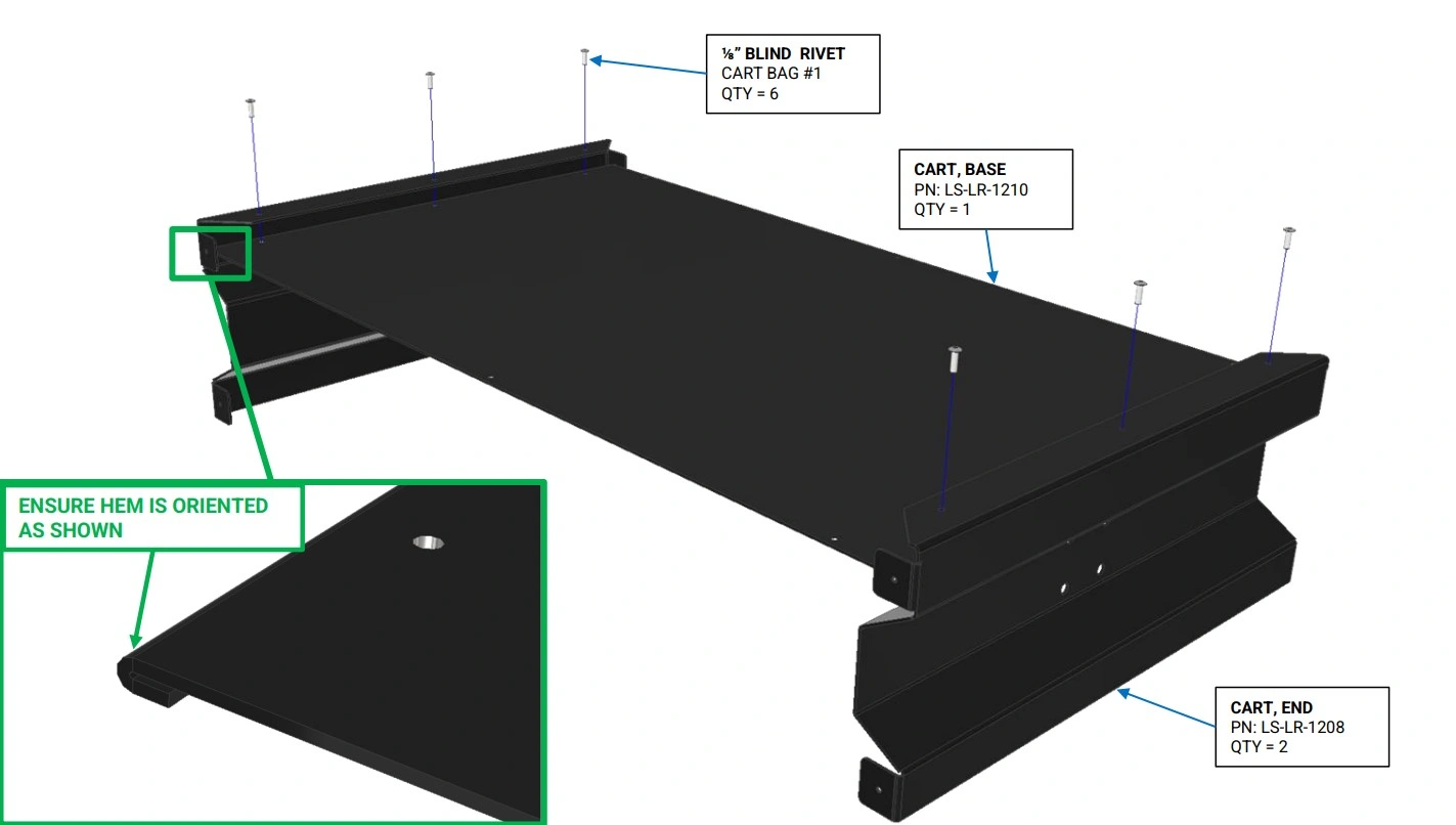
Instructions
- Locate the Cart, Base and Cart, End panels.
- Using the ⅛” Blind Rivets, rivet the Cart, Base to the Cart, End panels as shown. Ensure the hem of the Cart, Base is correctly oriented.
Materials
Parts
- (2) Cart, Side
Hardware
- (10) ⅛” Blind Rivets
Tools
- Rivet Gun
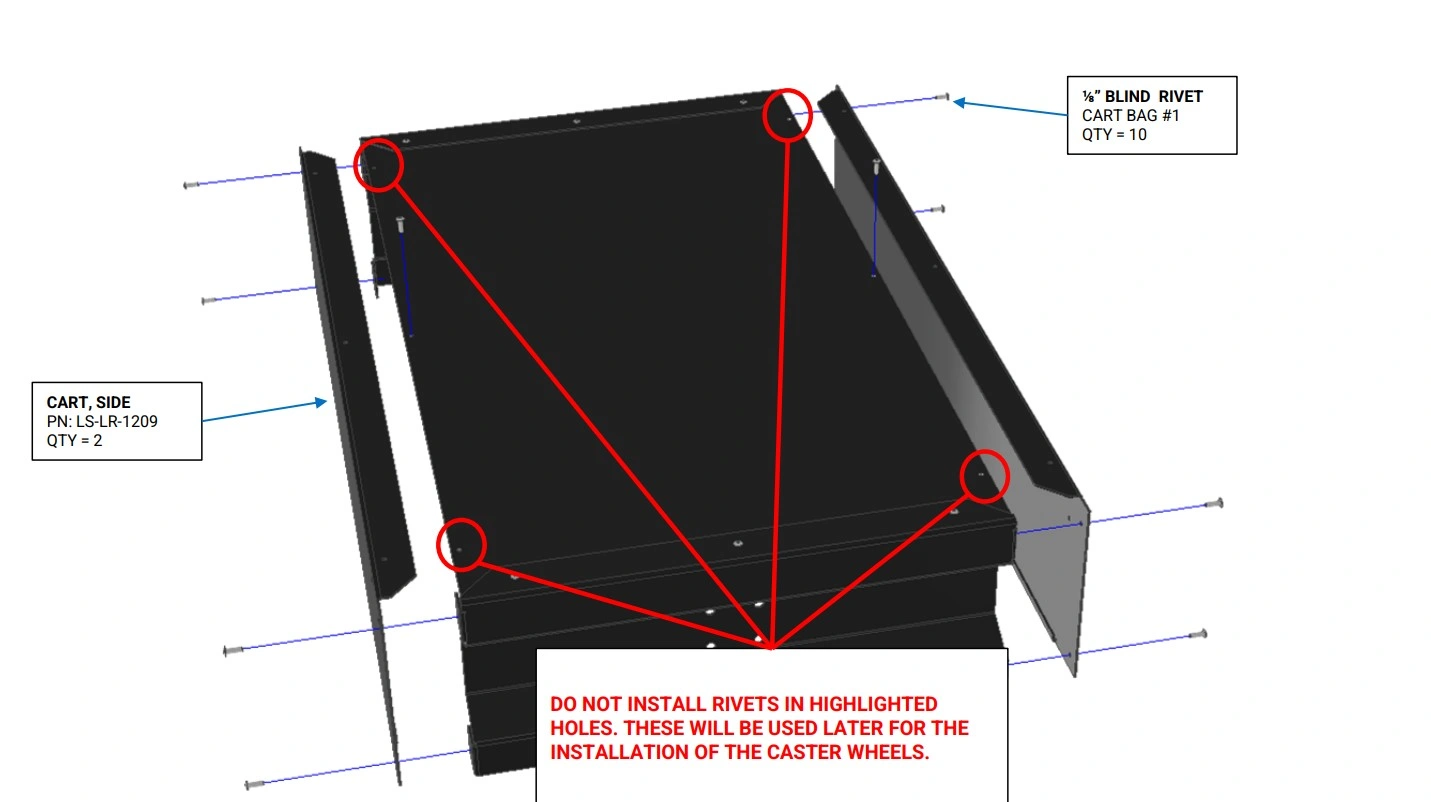
Instructions
- Locate the Cart, Side panels.
- Using the ⅛” Blind Rivets, rivet the Cart, Side panels to the Cart, Base as shown.
Materials
Parts
- (4) Edge Mount Bracket Caster
Hardware
- (12) ⅛” Blind Rivets
Tools
- Rivet Gun
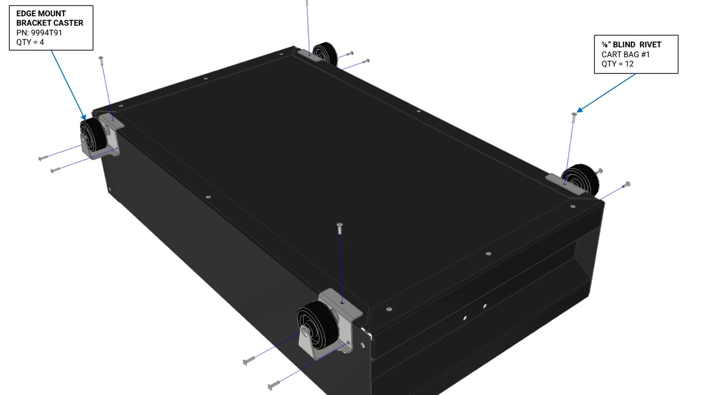
Instructions
- Locate the Edge Mount Bracket Casters.
- Using the ⅛” Blind Rivets, rivet the Edge Mount Bracket Casters panels to the Cart, Sides as shown.
Materials
Parts
- (1) Cushioned Round Grip
- (1) Assembly, Cart Handle
Hardware
- None
Tools
- None
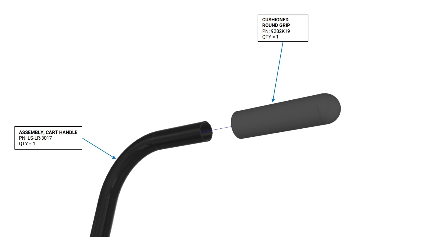
Instructions
- Locate the Assembly, Cart Handle, and the Cushioned Round Grip.
- Slide the Cushioned Round Grip on to the Assembly, Cart Handle as shown.
Materials
Parts
- (1) Assembly Cart Handle
Hardware
- (4) BHCS, M5 x 0.8 x 12mm
- (4) M5 Flange Nut
Tools
- 3mm Hex Key
- 8mm Wrench
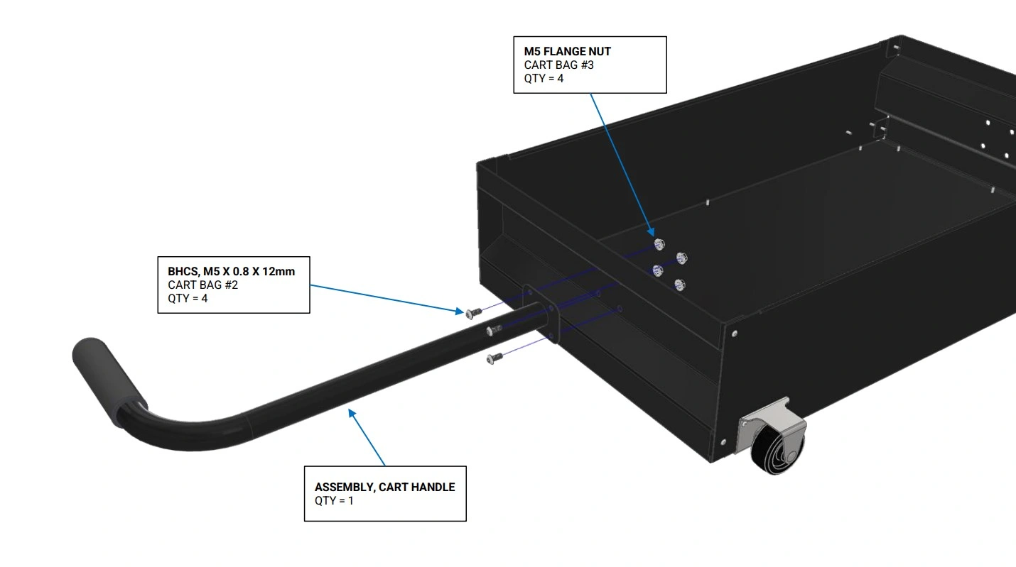
Instructions
- Bolt the Assembly, Cart Handle to the cart as shown
Materials
Parts
- None
Hardware
- None
Tools
- None
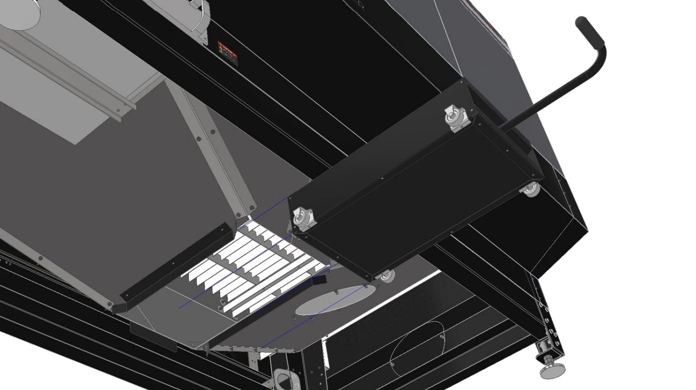
Instructions
- Slide the Cart Assembly between the guiding flanges at the bottom of the cut bed until it makes contact with the stop plate mounted to the back of the cut bed.
- This concludes the Part Retrieval Cart assembly guide.
8: Fill and Hook Up Chiller
The next step is to hook up and fill the chiller for operation.
Materials
Parts
- (1) NEMA 6-50 Straight Plug (Not Included)
Hardware
- None
Tools
- Screwdriver
- Wire Strippers
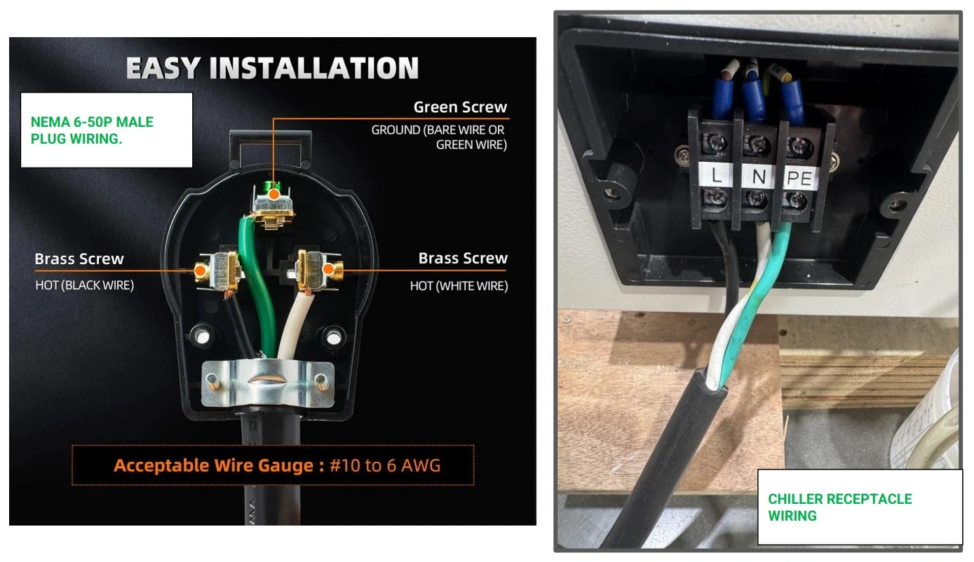
Instructions
-
In order to plug in the water chiller, you will need to purchase a NEMA 6-50 Plug from a local hardware store and wire it correctly.
ELECTRICAL SHOCKWARNINGInstall and maintain all electrical components in accordance with the National Electrical Code (NEC). If you have limited electrical knowledge/experience, hire a certified electrician to perform any and all electrical work.
- Next, locate the power input on the chiller and remove the plastic cover.
- Wire the black wire to L, the white wire to N, and the Green wire to PE.
- Re-install the plastic cover over the power input.
- Once wired, leave the machine unplugged until ready to operate the Apollo.
Materials
Parts
- (1) Water Chiller
Hardware
- None
Tools
- Distilled Water (6 Gallons)
- (Optional) Funnel
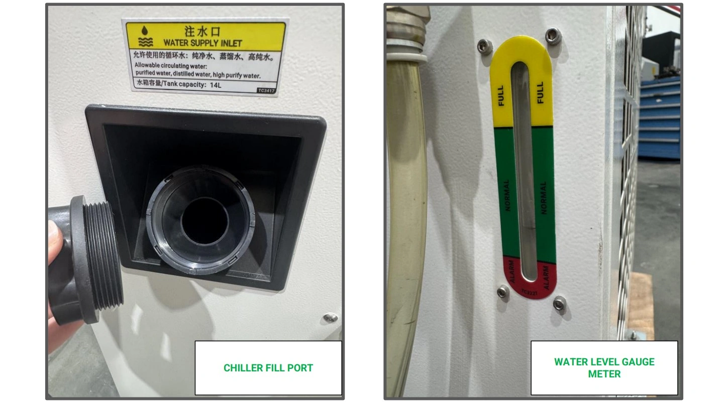
Instructions
- Locate the fill port on the back of the chiller and remove the cap.
-
Using distilled water, fill the water chiller’s reservoir until the water level of the tank reads full as indicated by the meter.
NOTEThe use of any water besides distilled water or highly purified water can/will damage your water chiller. Langmuir Systems is not responsible for improper use of the water chiller and any damage as a result is not covered by your Apollo’s warranty.
- Replace the fill cap on the unit.
Materials
Parts
- (1) Water Chiller
- (1) Apollo CNC Fiber Laser
- (1) Apollo Hook-up Kir
- (1) 25ft -10mm OD x 6.5mm ID Silicone Tubing (if Hook-up Kit not Purchased)
- (1) 25ft -12mm OD x 10mm ID Silicone Tubing (if Hook-up Kit not Purchased)
- (2) ½” - 12mm OD Tube Push-to-connect (if Hook-up Kit not Purchased)
- (2) ½” - 10mm OD Tube Push-to-connect (if Hook-up Kit not Purchased)
Hardware
- None
Tools
- (Optional) Tube cutters
- Teflon Tape/ Thread Sealant
Instructions
- Locate the Apollo Hook-up Kit or the separately purchased tubing and fittings required to connect the water chiller to the Apollo CNC Fiber Laser.
-
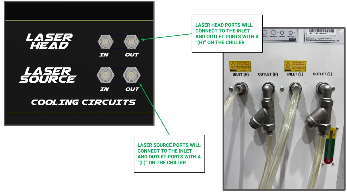
Using the ½” - 12mm OD Tube Push-to-connect fittings, secure the fitting to the ports of the water chiller labeled “Inlet (L)” and “Outlet (L).” Apply thread sealant/teflon tape to the threads.
NOTEFor application of thread sealant, we recommend 2-3 revolutions around the threading to provide a good seal.
- Repeat step C2 for the ½” - 10mm fitting on the ports labeled “Inlet (H)” and Outlet (H).”
-
Using the provided images, connect the chiller to Apollo. The inlet ports of the chiller will connect to the “in” ports of the Apollo and vice versa for the outlet and “out” ports.
NOTEAs a rule of thumb, we recommend keeping the chiller and gas bottles a minimum of 3 feet away from the Apollo. If desired, you may cut away unused tubing. Be sure to make a single square cut to ensure a secure seal once the tubing is installed in the push-to-connect fittings.
Materials
Parts
- None
Hardware
- None
Tools
- None
Instructions
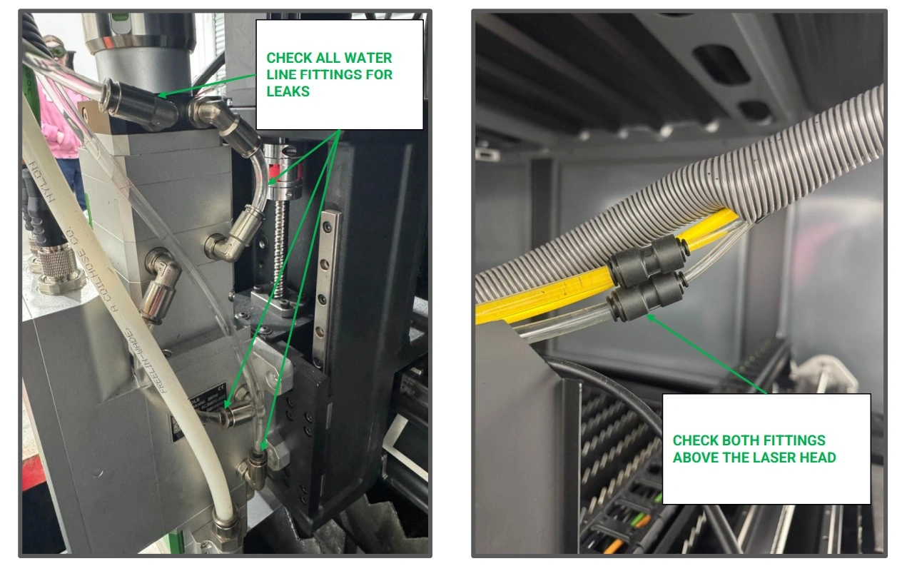
- Before turning on the chiller, it is important to check that all chiller line fittings are seated and well sealed.
-
Locate the fittings shown and ensure the tubing is fully seated in the push-to-connect fittings.
NOTEIt is recommended to have a second person present for the following step.
- Position yourself or another individual at the push-to-connect fittings around the laser head with a towel or cup to prevent water spillage in the event the fittings do not have a proper seal.
- Turn on the water chiller and allow the water to push through the lines up to your laser head. If any water begins to leak, especially around the laser head, turn the chiller off and check the seals/tubing of your water lines.
- If no leaks are present, your water chiller is successfully installed.
9: Connect Gas Bottles
The next step is to hook up gas bottles to the machine.
Materials
Parts
- (1) Oxygen bottle
- (1) Nitrogen Bottle (if needed)
- (1) Bottle Rack/Storage Solution
Hardware
- None
Tools
- Dolly(Optional)
Instructions
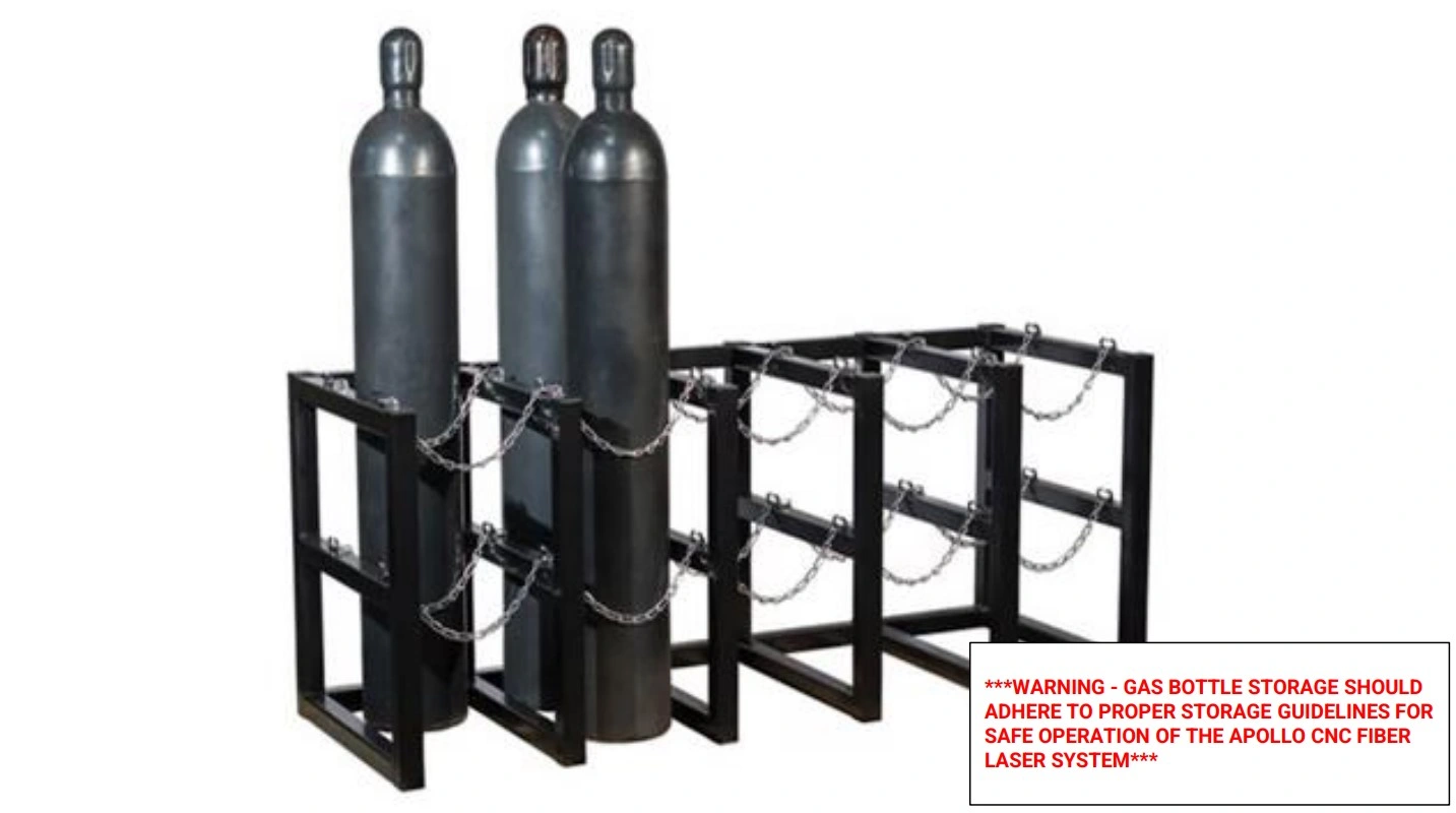
- Before connecting any cutting gas to the Apollo, gas cylinders should and must be stored in a safe position and secured to an upright structure for proper storage. Determine where Apollo will be in your shop, and place the gas cylinders accordingly, accounting for 3 feet of clearance between the cylinders and the machine.
GAS BOTTLE
WARNING
Gas cylinders are safe and reliable provided the proper safety precautions are taken. Whether empty or full, and regardless of size, gas cylinders MUST be secured with a strong chain or strap to prevent tipping and falls and potentially fatal situations. Even vibrations from the Apollo’s moving gantry can be a hazard for unsecured bottles. Ensure you are familiar with proper and safe techniques for transporting and handling gas cylinders before undertaking the machine setup.
FIRE HAZARD
WARNING
NEVER store gas cylinders near an open flame, hot elements, or in an environment which spontaneous combustion can occur. Failure to properly secure gas cylinders can result in serious injury and death.
Materials
Parts
- (1) Oxygen bottle
- (1) Apollo Hook-up Kit
- (1) Oxygen Regulator (if Hook-up Kit not purchased)
- (1) Oxygen Flashback Arrestor (if Hook-up Kit not purchased)
- (1) 37 Degree Flared Fitting (if Hook-up Kit not purchased)
- (1) ¼” - 10mm Straight Push-to-connect (if Hook-up Kit not purchased)
Hardware
- None
Tools
- 1-1/8th Open End Wrench
- 17mm Open End Wrench
- ¾” Open End Wrench
- 11/16” Open End Wrench
- Teflon Tape
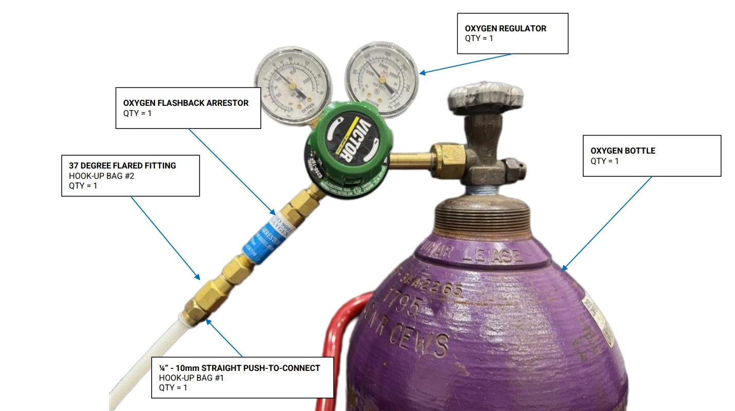
Instructions
NOTE
We recommend applying thread sealant to all joints in the Gas Cylinder regulator assembly. For application of thread sealant, we recommend 2-3 revolutions around any and all threading to provide a good seal.
- Locate the Apollo Hook-up Kit or the components you sourced yourself.
- Connect the Oxygen Flashback Arrestor to the outlet port of the oxygen regulator.
- Next, connect the 37 Degree flared fitting to the end of the flashback arrestor.
- Lastly, connect one of the ¼” - 10mm Straight Push-to-connect fittings to the previously installed flared fitting.
- With the Oxygen cylinder valve closed, connect the regulator assembly to the bottle.
Materials
Parts
- (1) Nitrogen Bottle
- (1) Apollo Hook-up Kit
- (1) Nitrogen Regulator (if Hook-up Kit not purchased)
- (1) ¼” - 10mm Straight Push-to-connect (if Hook-up Kit not purchased)
Hardware
- None
Tools
- 27mm Open End Wrench
- 19mm Open End Wrench
- 16mm Open End Wrench
- Teflon Tape
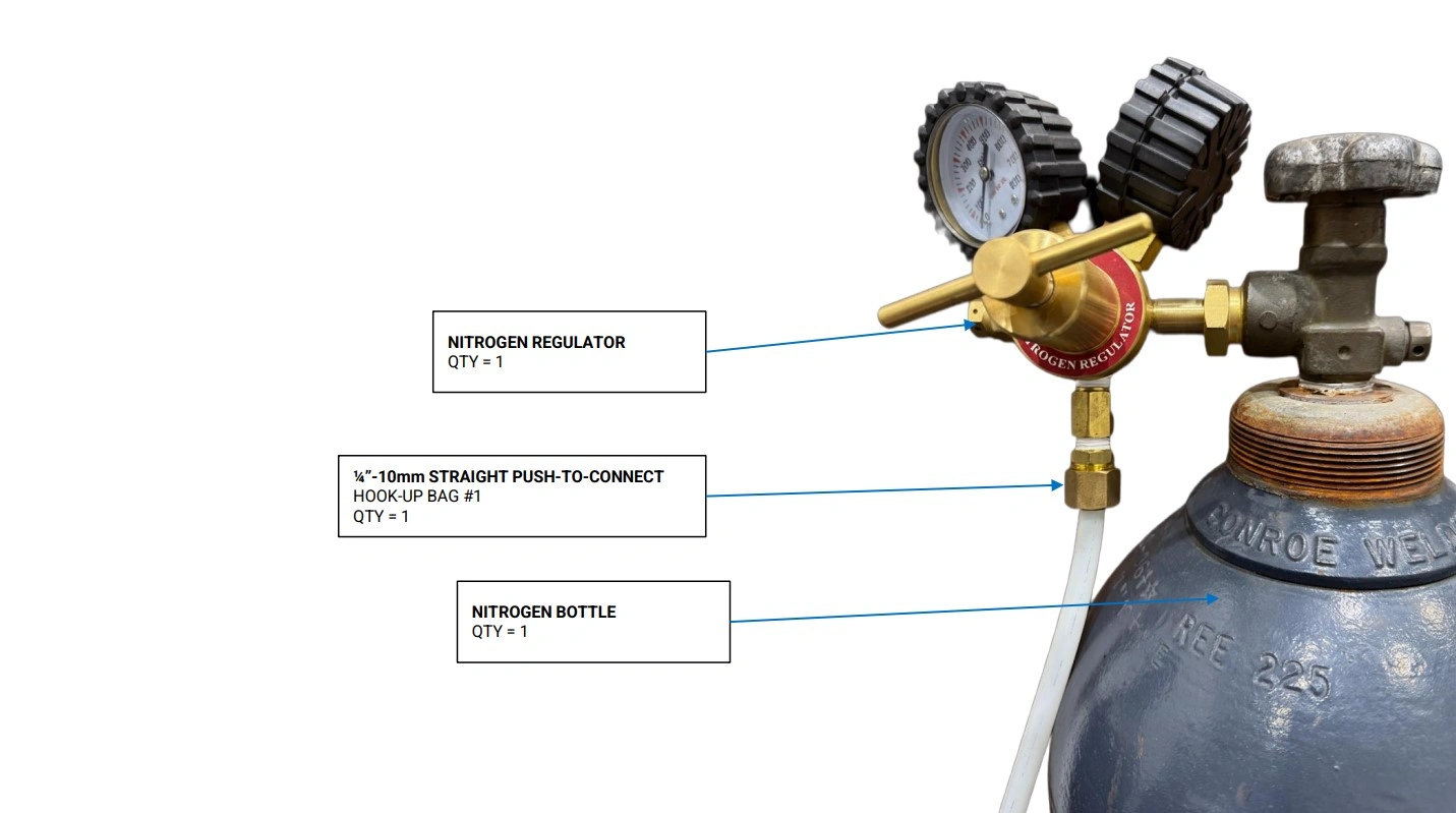
Instructions
- Locate the Apollo Hook-up Kit or the components you sourced yourself.
- Connect the ¼” - 10mm straight push-to-connect to the outlet port of the Nitrogen regulator.
- With the nitrogen cylinder valve closed, connect the Nitrogen regulator assembly to the Nitrogen Cylinders
Materials
Parts
- (1) Oxygen Bottle w/ regulator
- (1) Nitrogen Bottle w/ regulator
- (1) Apollo Hook-Up Kit
- (1) 50ft - 10mm OD x 8mm ID Hard Nylon Tubing (if Hook-up Kit not Purchased)
Hardware
- None
Tools
- Pipe/Tube Cutters

Instructions
- Locate the 50ft - 10mm OD x 8mm ID Hard Nylon Tubing that came with your Hook-up kit or that you purchased separately.
- Connect one end of the tubing to the push-to-connect fitting located on the oxygen bottle. If necessary, you may need to cut the tubing square for a proper seal.
-
NOTEAs a rule of thumb, we recommend keeping the chiller and gas bottles a minimum of 3 feet away from the Apollo. If desired, you may cut away unused tubing. Be sure to make a single square cut to ensure a secure seal once the tubing is installed in the push-to-connect fittings.
- If not done already, ensure the oxygen bottle is located safely away from the Apollo and where you plan to store the bottle during machine operation.
- Determine the appropriate length of tubing necessary to reach the port labeled “O2” on the Apollo without adding any sharp bends or unnecessary tension to the tubing. Cut the end of the tube square to ensure a proper seal.
- Connect the end of the tube to the oxygen port.
- With the remaining length of tube, repeat steps D1-D5 for your nitrogen gas if needed, being sure to use the port on Apollo labeled “N2”
Materials
Parts
- (1) Oxygen Cylinder (Connected)
- (1) Nitrogen Cylinder (Connected)
Hardware
- None
Tools
- None
Instructions
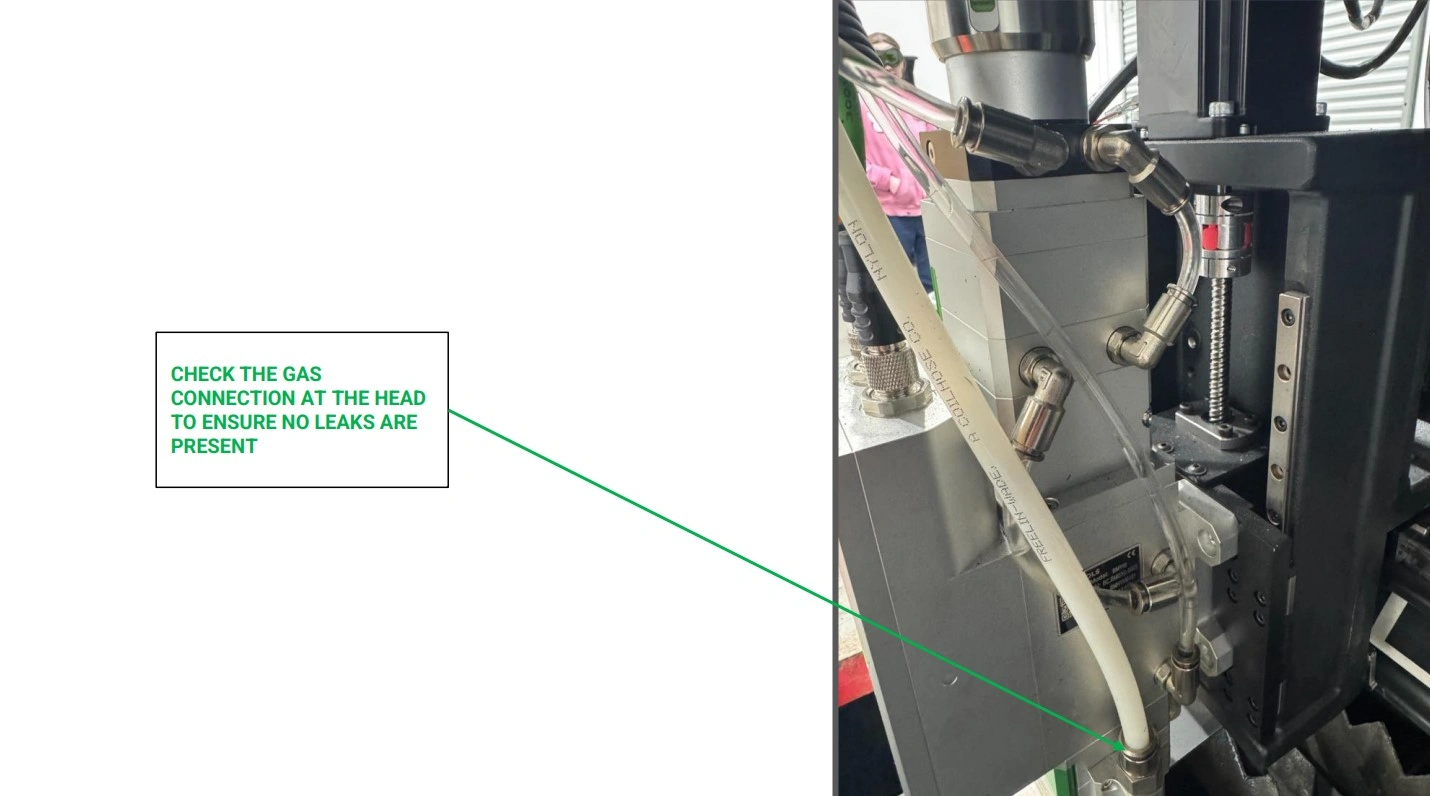
NOTE
The following steps use cutting gas to check for leaks. If you wish to save cutting gas, you may use compressed air if you have the proper connections.
- Using the oxygen cylinder, open the valve on the top of the bottle until the regulator dial reads 100 psi.
- Listen carefully around the Apollo for any signs of a gas leak. If a leak is present, return to the cylinder and close the valve, turning off the oxygen supply.
-
Check any and all oxygen fittings starting from the regulator and working your way to the Apollo’s gas management system.
NOTETo easily locate a gas leak in the gas system, you may mix soap and water together in a spray bottle and spray down the tubing connection points. If any bubbles arise from the soapy water, this indicates a leak that needs to be addressed.
- Once all oxygen connections are secured and verified to not be leaking, repeat steps E1-E3 for the high pressure/ Nitrogen side of the gas system.
10: PC Setup
The next step is to set up the Apollo Control PC.
Materials
Parts
- (1) Apollo Power Cord
Hardware
- None
Tools
- None
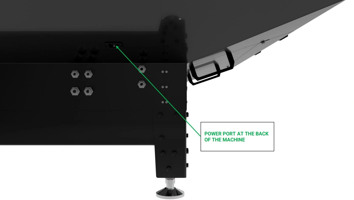
Instructions
- Locate the Apollo Power Cord that came with your unit.
- Using the power receptacle on the back of the machine, plug the power cord into unit.
- Plug the cord into your available 240V Outlet.
11: Limit Switch Checks
The next step is to check that all limit switches trigger appropriately before homing.
Materials
Parts
- None
Hardware
- None
Tools
- None
Instructions
- With the E-stop deactivated and the power on, navigate to the screen of your apollo unit and open LaserControl.
- If needed, update the LaserControl Software and any necessary drivers by following on screen prompts as needed.
- At this point in the setup, we recommend becoming familiar with LaserControl for best results with your cutting. See our software overview guide Here →
Materials
Parts
- None
Hardware
- None
Tools
- None
Instructions
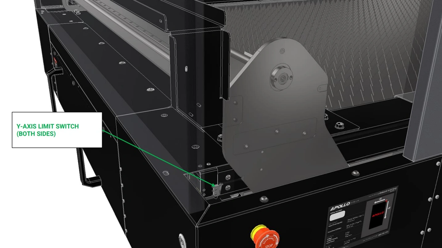
- Locate the Y-axis limit switches located on the garage side of the unit.
- When actuated, LaserControl will indicate the switches have been triggered by indicating green in the limit switch area.
- With the assistance of a second person, have one individual actuate the switches while the other monitors LaserControl.
- Verify that both Y-Axis switches indicate properly inside laser control.
- Using LaserControl, slowly jog the gantry back towards the Y-axis limit switches until the limit switch stop screws in the gantry uprights are almost touching the arms of the Y-Axis limit switches.
- Step the gantry into the limit switches using 0.001” increments until one or both limit switches trigger.
- If only one limit switch triggers, adjust the limit switch stop screw and jam nut on the un-triggered limit switch such that it is just barely triggered, and jog the gantry away from the Y-Axis limit switches.
- Repeat steps B5-B7 until both limit switches trigger at the same time. Tighten the jam nuts securing both limit switch stop screws to ensure they remain in place.
Materials
Parts
- None
Hardware
- None
Tools
- None
Instructions
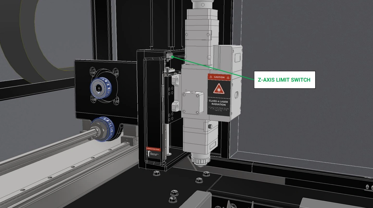
- Locate the Z-Axis limit switch on thtel:8335264797e Apollo’s Gantry.
- Repeat Steps B2-B4 for the Ztel:8335264797-Axis Limit Switch
Materials
Parts
- None
Hardware
- None
Tools
- None
Instructions
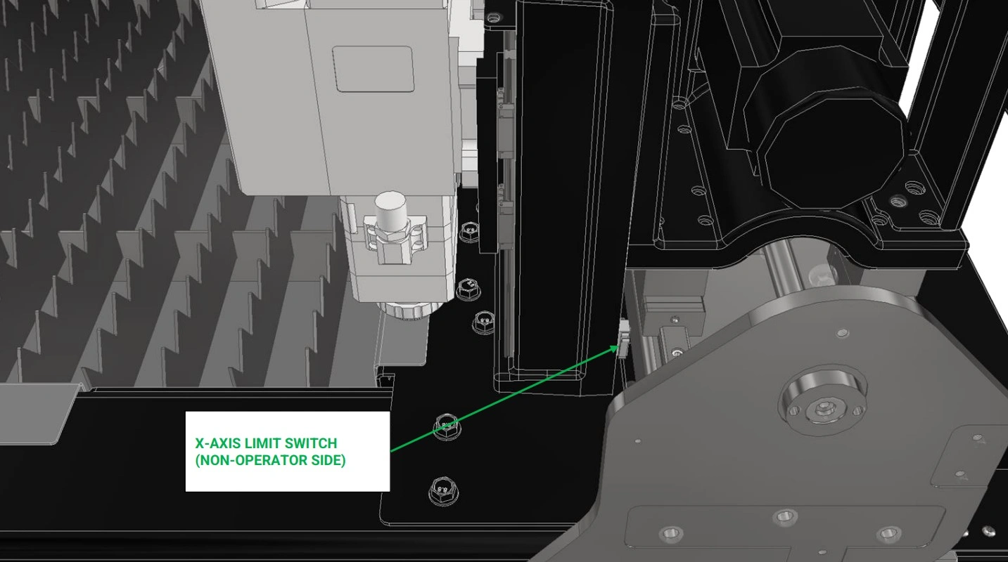
- Locate the X-Axis limit switch on thtel:8335264797e Apollo’s Gantry.
- Repeat Steps B2-B4 for the Xtel:8335264797-Axis Limit Switch
Materials
Parts
- None
Hardware
- None
Tools
- N/A
Instructions
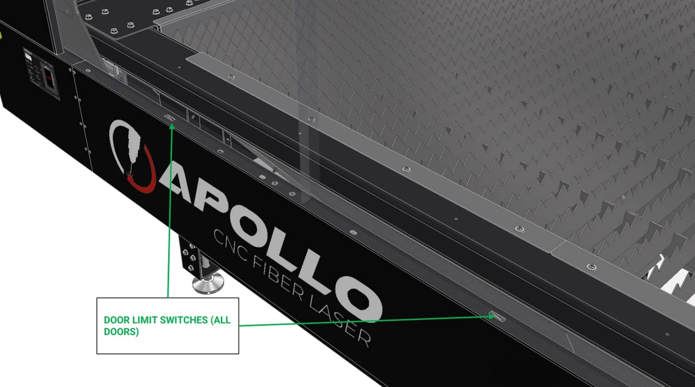
- The last limit switches to test are the door limit switches.
- Locate the limit switch under each door panel of the Apollo’s Enclosure.
- Install each door into the enclosure such that each limit switch is actuated.
- Once every switch is actuated, verify that LaserControl has indicated green, verifying that the switches are performing as expected.
- If LaserControl does not indicate green, check each switch to ensure they are properly activated. If issues still occur, contact our technical support hotline at (833) 526 - 4797
12: Home Machine
The final step is to home the machine using Laser Control.
Materials
Parts
- N/A
Hardware
- N/A
Tools
- N/A
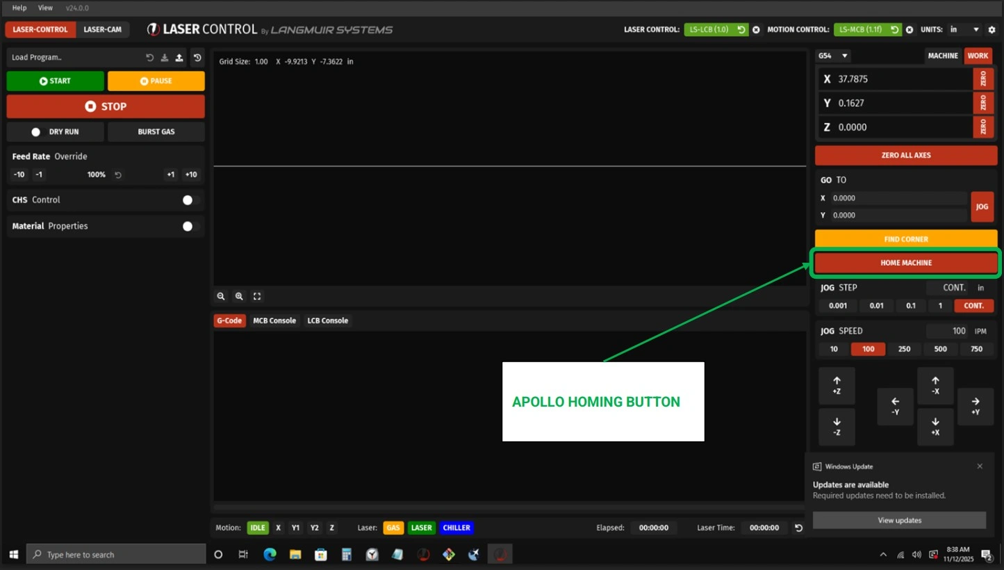
Instructions
NOTE
Your Apollo was squared in-house on the assembly line and validated by an assembly technician, However, we highly recommend ensuring the Y-axis limit switches are appropriately adjusted before running the first homing sequence on your machine. Referencing the procedure given in Section 12 steps B5-B8.
- With the limit switches properly adjusted and validated to be working, run the homing sequence to ensure the gantry is square.
13: First-Time User Setup & Operation
This guide outlines the recommended steps for first-time operation of your Apollo system. Followingthese instructions will help ensure safe operation, proper machine setup, and optimal cuttingperformance.
IMPORTANT – Zero Position Requirement
If LaserControl resets or the system is powered down, you MUST re-establish the zero position before continuing operation.
Failure to reset the zero potions can result in the following: Incorrect machine movement, Loss of positional accuracy, and Damage to the machine or cutting material. Always perform a "Zero All Axes" command after restarting LaserControl or powering the machine on. This step ensures the system has a correct reference point for all movement and cutting operations.
Failure to reset the zero potions can result in the following: Incorrect machine movement, Loss of positional accuracy, and Damage to the machine or cutting material. Always perform a "Zero All Axes" command after restarting LaserControl or powering the machine on. This step ensures the system has a correct reference point for all movement and cutting operations.
1. Initial System Setup
Before beginning operation, ensure the machine and software environment are properly initialized.This step prepares the system for safe and accurate operation.
- Power on the Apollo system and verify all components initialize correctly
- Launch the LaserControl software and confirm communication with the machine
- Load your material securely onto the cutting bed, ensuring it is flat and stable
- Visually inspect the work area for obstructions or loose items
2. Set the Zero Position
Establishing a zero position provides the machine with a reference point for all motion and cuttingoperations. This is one of the most critical steps in the setup process.
- Verify the Z-axis (laser head) has sufficient clearance before moving
- Position the laser head directly at the material surface
- Select “Zero All Axis” in LaserControl to define the reference position
- Repeat this process any time the machine position is changed or reset
3. Prepare Personal Protective Equipment (PPE)
Proper safety equipment is required at all times when operating the Apollo system to protect againsthazards associated with laser cutting.
- Wear approved safety goggles designed for laser operation
- Use a respirator or gas mask when cutting materials that produce fumes
- Wear appropriate work gloves when handling materials
- Ensure all PPE is properly fitted and in good condition before use
4. Verify Air and Cooling Systems
The Apollo system relies on proper gas flow and cooling to maintain cutting performance andprevent damage to components.
- Turn on your selected gas supply (On, Nn, or air compressor)
- Confirm the chiller is powered on and functioning (if equipped)
- Use the “Burst Gas” function in LaserControl to verify airflow through the laser head
- Listen and visually confirm consistent airflow before proceeding
5. Load and Position Your Program
Accurate positioning and program setup ensure your cuts are placed correctly on the material andwithin machine limits.
- Use the X and Y directional controls to move the torch head
- Operate at a controlled speed (recommended approximately 250 IPM) for safe positioning
- Load your desired cut program into LaserControl
- Select “Zero All Axis” after loading the program
- Confirm the torch head remains within machine travel limits
- Re-zero the machine after any manual adjustments to positioning
6. Set Cutting Parameters
Before cutting, the system must be configured to match the selected material and cuttingconditions.
- Run CHS Control (this process may take several minutes to complete)
- Run AF Control to calibrate the system
- Load appropriate Material Properties to match your material type and thickness
- Verify all parameters before proceeding to cutting
7. Begin Cutting Operation
Once all setup steps are complete, you may begin the cutting process.
- Put on all required PPE before starting the laser
- Notify all personnel in the area that cutting is about to begin
- Turn on the laser source using the provided key
- Press the control button to arm the laser and begin operation
8. Monitor the Cutting Process
Continuous monitoring ensures proper operation and allows you to identify any issues early.
- Observe cutting speed and adjust if necessary
- Listen for consistent and uninterrupted gas flow
- Monitor LaserControl for progress and estimated completion time
- Be prepared to stop the machine if any irregularities occur
Apollo camera + light add-on
Images in this Guide
The assembly drawings and pictures included in this guide can be expanded to
full-screen and zoomed to provide more detail on a given step.
1: Install the Camera
The first step in the assembly process is to mount the camera.
CAMERA AND LIGHTING KIT : If you are installing the Camera and Lighting Kit, follow the guide below. Otherwise, SKIP IT→
Materials
Parts
- (1) Camera with Mount
Hardware
- (1) ¼-20 SHCS
Tools
- 3/16” Hex Key
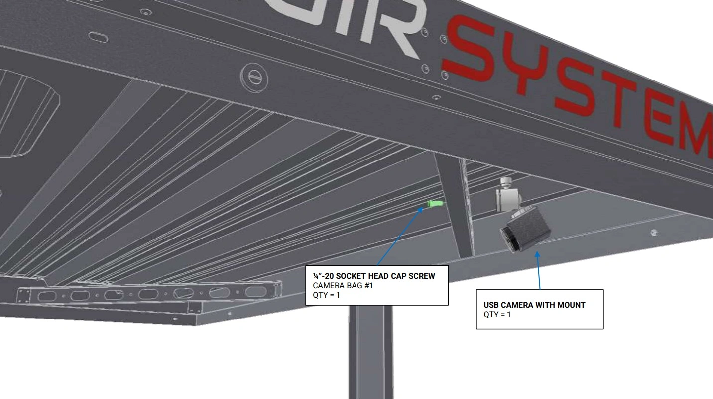
Instructions
- Locate the Camera with Mount that came with your add-on kit
- Select one of the 4 corner braces located on the roof of the Apollo enclosure to mount the camera to. We recommend mounting the camera on the operator side at the far end of the enclosure for best viewing results.
- Mount the camera to the desired clearance hole using the fastener provided.
2: Install the Light
The second step in the assembly process is to mount the Light.
Materials
Parts
- (1) Camera with Mount
Hardware
- (1) ¼-20 SHCS
Tools
- 3/16” Hex Key
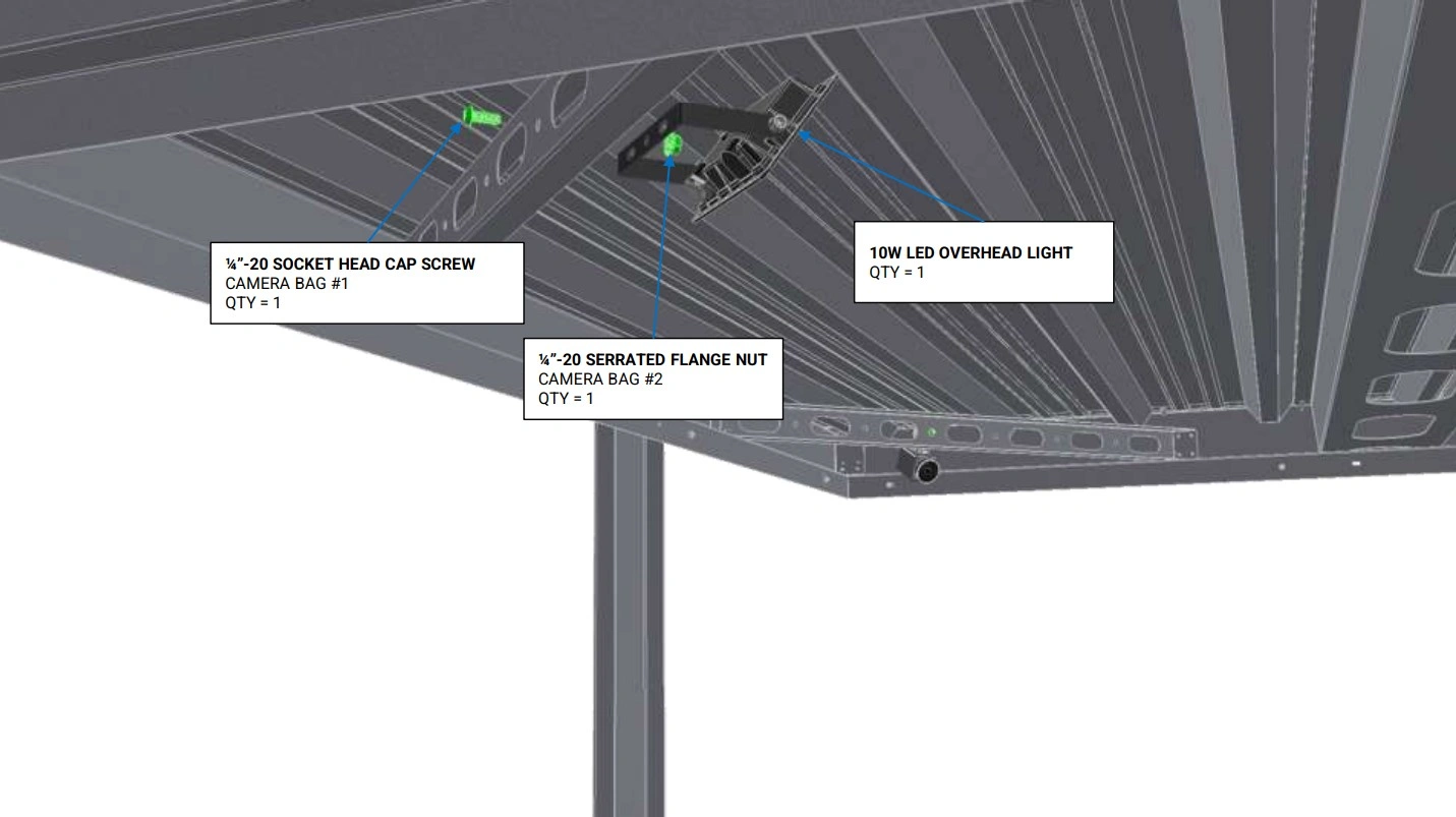
Instructions
- Locate the Camera with Mount that came with your add-on kit
- Select one of the 4 corner braces located on the roof of the Apollo enclosure to mount the camera to. We recommend mounting the camera on the operator side at the far end of the enclosure for best viewing results.
- Mount the camera to the desired clearance hole using the fastener provided.
3: Cable Management
The third step in the assembly process is layout the cable management
Materials
Parts
- None
Hardware
- None
Tools
- None
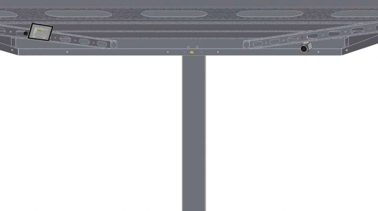
Instructions
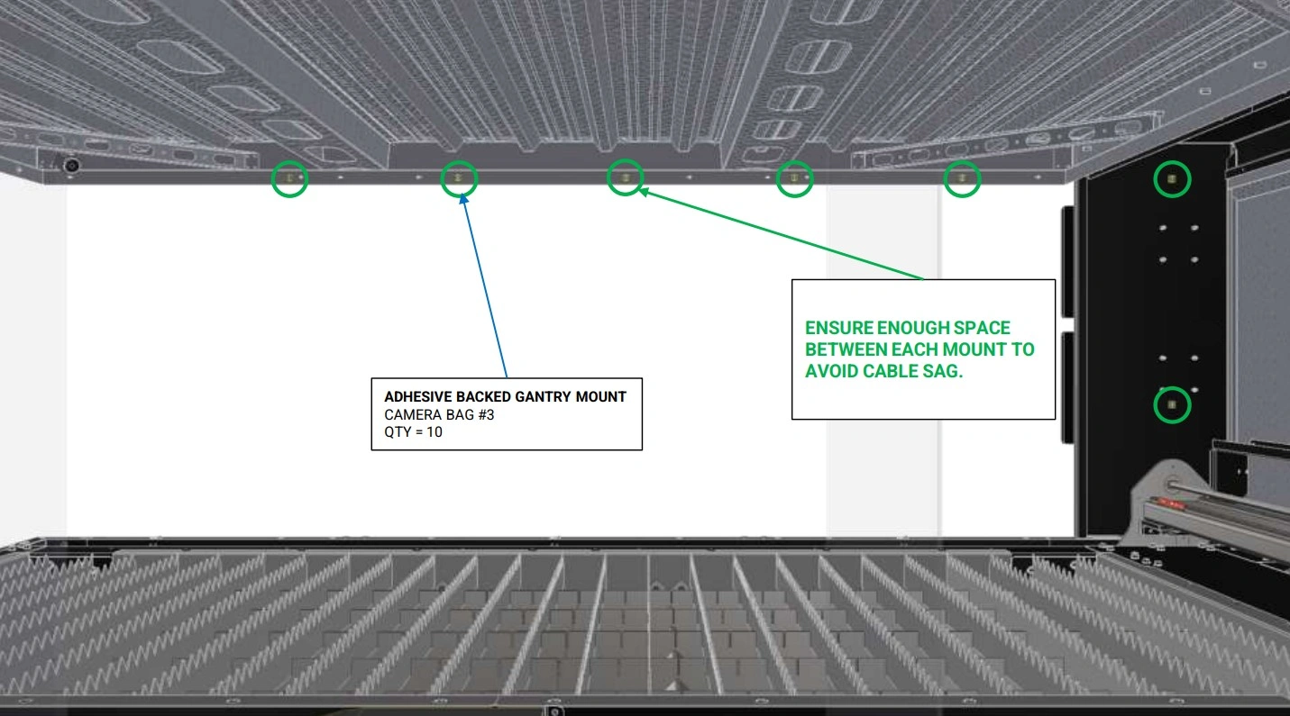
NOTE
This is the approximate camera and light mounting locations. To utilize other locations, modifications to the cable lengths will be required.
Materials
Parts
- (1) Camera with Mount
- (1) 10W LED Overhead Light
Hardware
- (20) Adhesive Backed Cable Tie Mount
- (20) Cable Ties
Tools
- Isopropyl Alcohol
- Microfiber cloth
Instructions
NOTE
The light will get routed on the opposite side of the unit in the same manner (not shown).
- Using Isopropyl Alcohol and a microfiber cloth, wipe down the inner perimeter of the roof where you plan to run the camera’s cable.
-
Using the provided cable management, Attach the Adhesive Backed Cable Tie Mount along the inside perimeter of the enclosure roof.
NOTEWe recommend waiting a minimum of 10 minutes before securing the cables to the adhesive mounts to allow for proper adhesion.
- Secure the cable to the cable tie mounts using the provided Cable ties.
- The USB Camera should be routed on the operator side and the light should be routed on the opposite side.
Materials
Parts
- None
Hardware
- (2) Adhesive Backed Cable Tie Mount
Tools
- Isopropyl Alcohol
- Microfiber cloth
Instructions
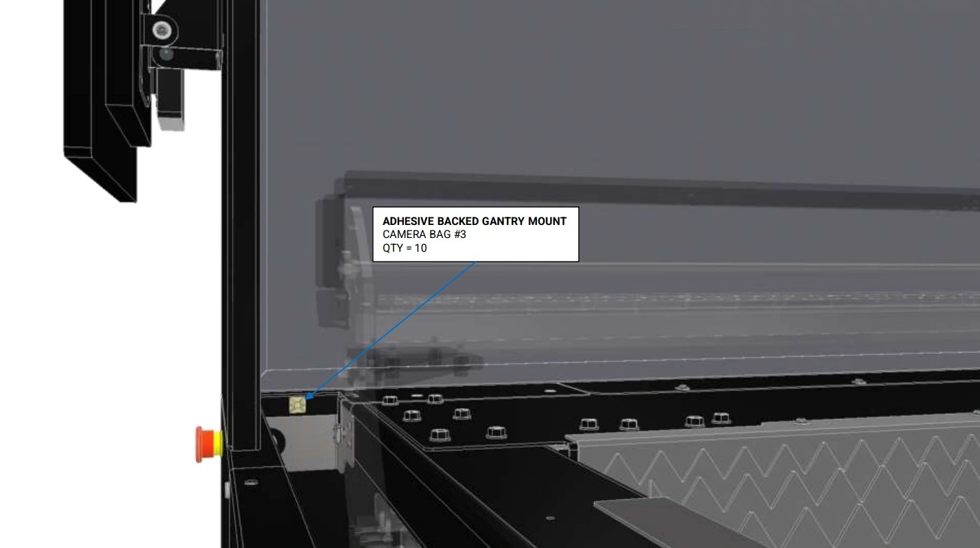
NOTE
The light will get routed on the opposite side of the unit in the same manner (not shown).
- Place the remaining Adhesive Backed Cable Tie Mount in the location shown.
- Do not secure the camera or light cables to these mounts at this time.
4: Routing the Camera
The Fourth step in the assembly process is to route the camera cable through the enclosure.
Materials
Parts
- None
Hardware
- None
Tools
- 4mm Hex Key
Instructions
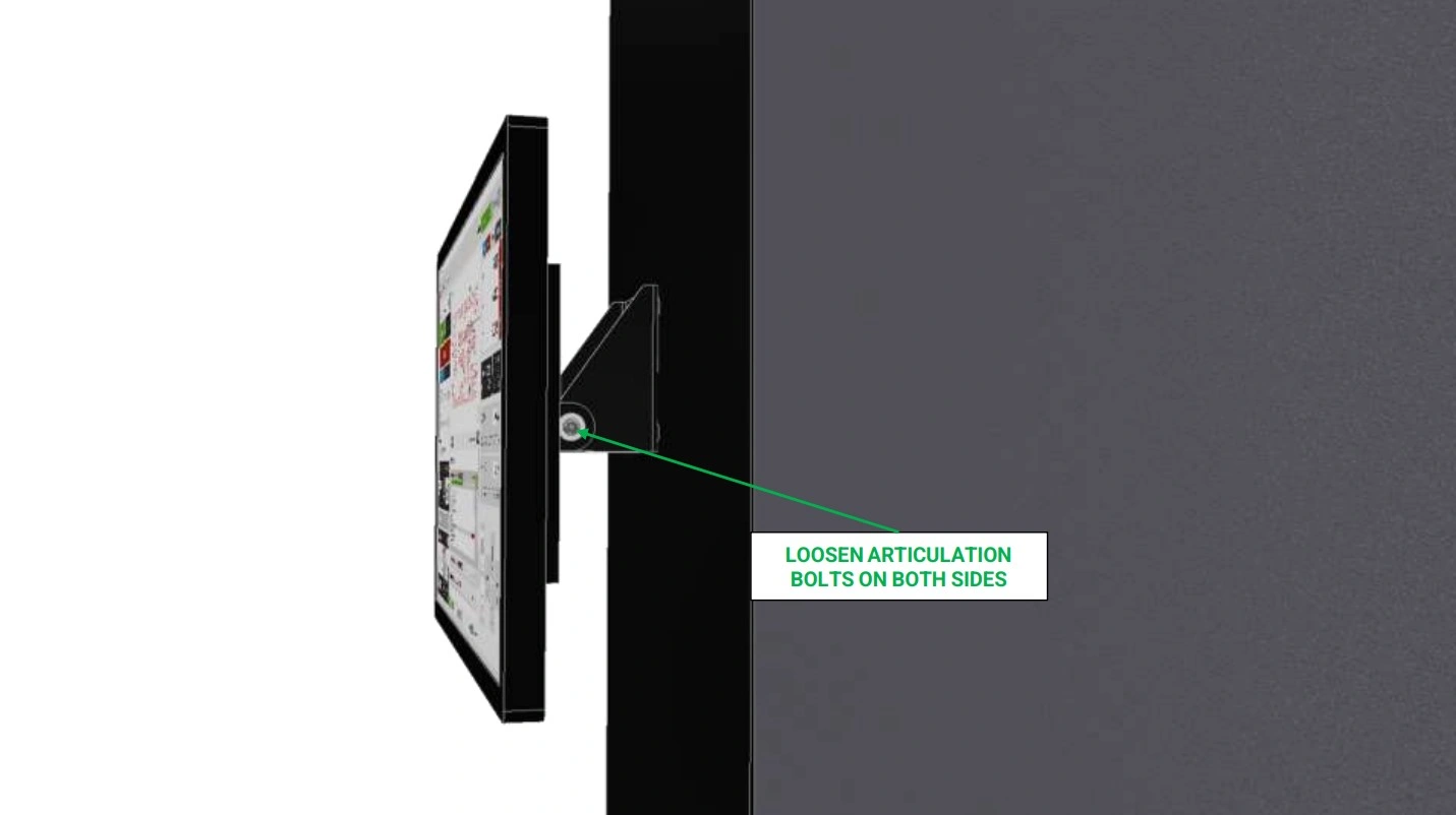
- If installed, locate the monitor that came standard with your Apollo and locate the articulation adjustment screws shown.
- Using a 4mm Hex Key, loosen the bolts such that the monitor can freely rotate into its down position.
- If needed, unplug any cables to allow for easy removal of the screen.
Materials
Parts
- None
Hardware
- None
Tools
- 4mm Hex Key
Instructions
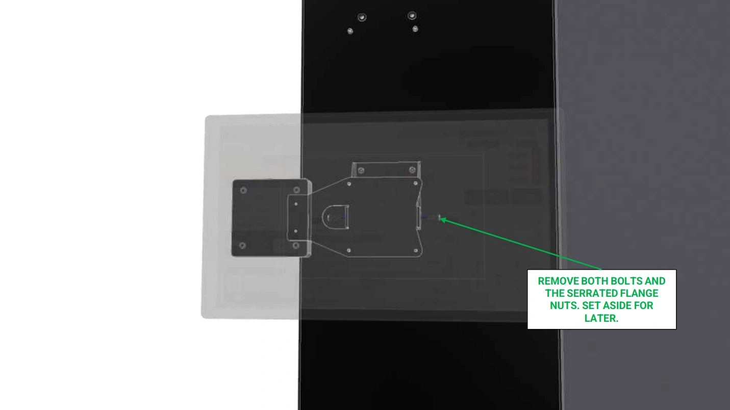
-
While being sure to support the monitor, unscrew the articulation point bolts and remove them so that you can easily pull the monitor off the enclosure.
NOTEIt may be necessary to have another person support the screen while you remove the nuts and bolts securing it in place.
- Set the monitor aside for now.
Materials
Parts
- None
Hardware
- None
Tools
- Drill
- 24mm Hole Saw bit
- Ruler
- Center Punch
Instructions
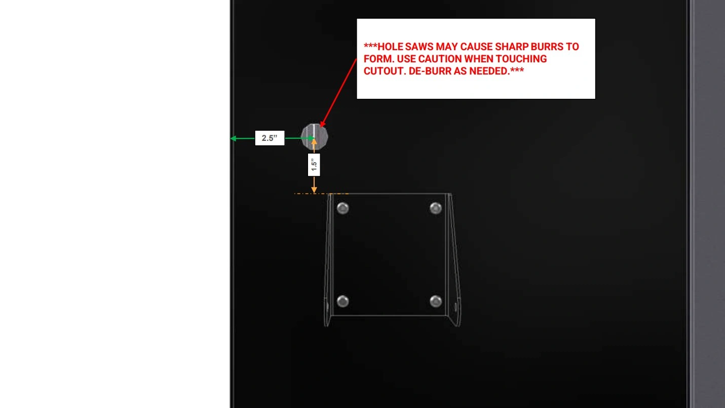
- With the monitor removed, use the existing mounting bracket and a ruler/measuring tape to mark a point approximately 1.5” above the bracket and 2.5” from the back of the enclosure.
-
Using a center punch, mark the location of the center point
Safety GlassesWARNINGIt is recommended to wear safety glasses as PPE during this step.
- With a 24mm Hole saw bit, bore a hole through the enclosure as shown at the center punch location.
- If significant burrs are present, use a deburring knife to remove them.
Materials
Parts
- (1) USB Panel Mount Interconnect
Hardware
- None
Tools
- None

Instructions
- Locate the USB Panel Mount Interconnect that came with your kit.
- Remove the securing nut on the back of the interconnect.
- Fasten the USB Panel Mount Interconnect into the hole and secure in place with the nut.
- Plug the Male-USB of the camera cable into the installed interconnect on the inside of the enclosure.
5: Mounting the Second Monitor
The fifth step in the assembly process is assemble and mount the second monitor.
Materials
Parts
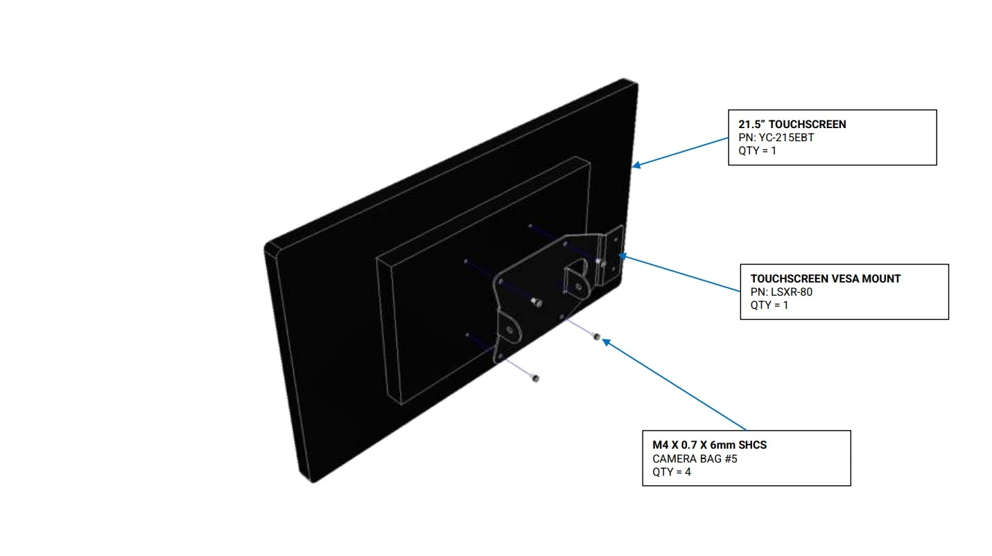
- (1) 21.5” Touchscreen
- (1) Touchscreen Vesa Mount
Hardware
- (4) M4 x 0.7 x 6mm SHCS
Tools
- 2.5mm Hex Key
Instructions
- Locate the 21.5” Touchscreen and Touchscreen Vesa Mount that arrived with your kit.
- Using the hardware provided in the touchscreen packaging, secure the Touchscreen Vesa Mount to the back of the monito as shown.
Materials
Parts
- (1) Touchscreen Pivot Bracket
Hardware
- (4) M6 x 1 x 16mm SHCS
Tools
- 4mm Hex Key
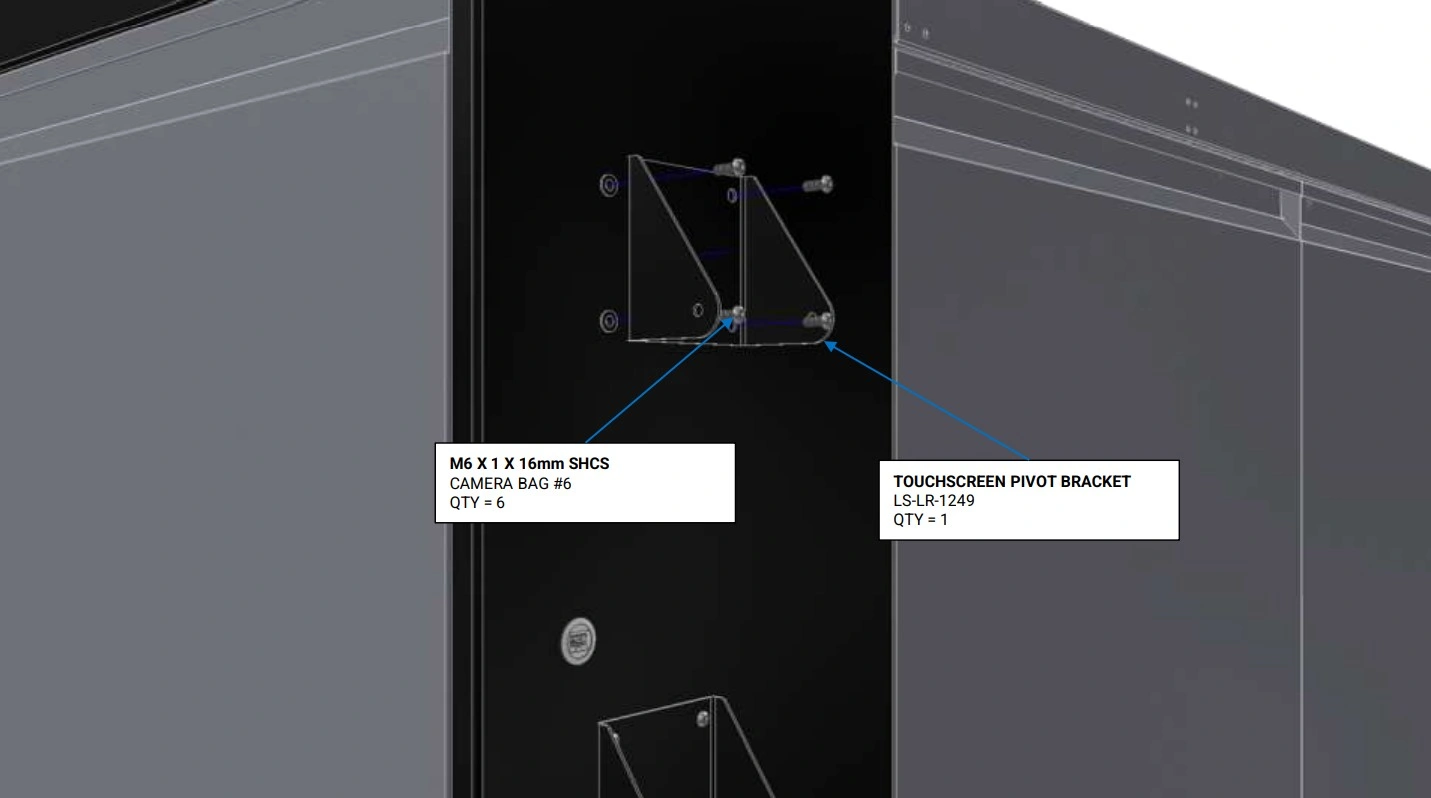
Instructions
- Locate the Touchscreen Pivot Bracket that came with your kit.
- Using the hardware shown, secure the pivot bracket to the enclosure’s rivet nuts located above the monitor that came standard with your Apollo.
Materials
Parts
- (1) Touchscreen Pivot Bracket (installed)
- (1) 21.5” Touchscreen
- (1) Touchscreen Vesa Mount
- (1) Previously Removed Monitor
Hardware
- (2) M6 x 1 x 16mm SHCS
- (2) M6 x 1 Serrated Flange Nut
- (2) M6 Washer
Tools
- 4mm Hex Key
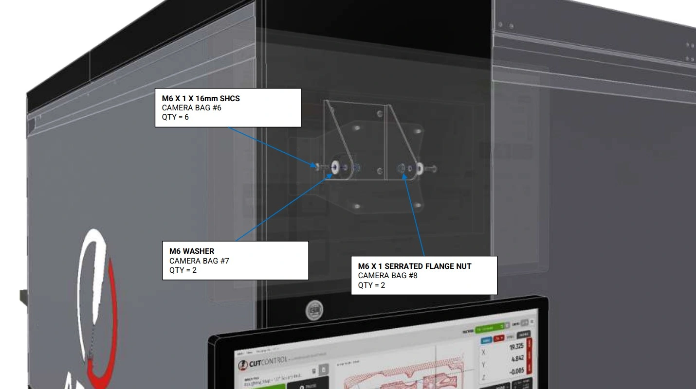
Instructions
- Using the fasteners shown, install the second monitor onto the installed pivot bracket.
- Repeat step C1 for the previously removed monitor directly below.
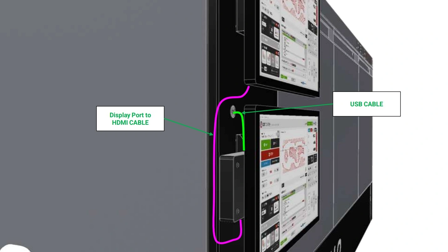
6: Connecting the Camera
The sixth step in the assembly process is to connect the camera to the PC and second monitor.
Materials
Parts
- (1) USB-A to USB-A Cable
- (1) Display Port to HDMI Cable
Hardware
- None
Tools
- None
Instructions
- Using the newly installed panel mount interconnect, plug in one side of the USB-A to USB-A cable (GREEN) into the interconnect and the other side into the PC attached to the lower monitor bracket.
- Using the provided USB C to HDMI cable (PINK), connect the PC to the second monitor above.
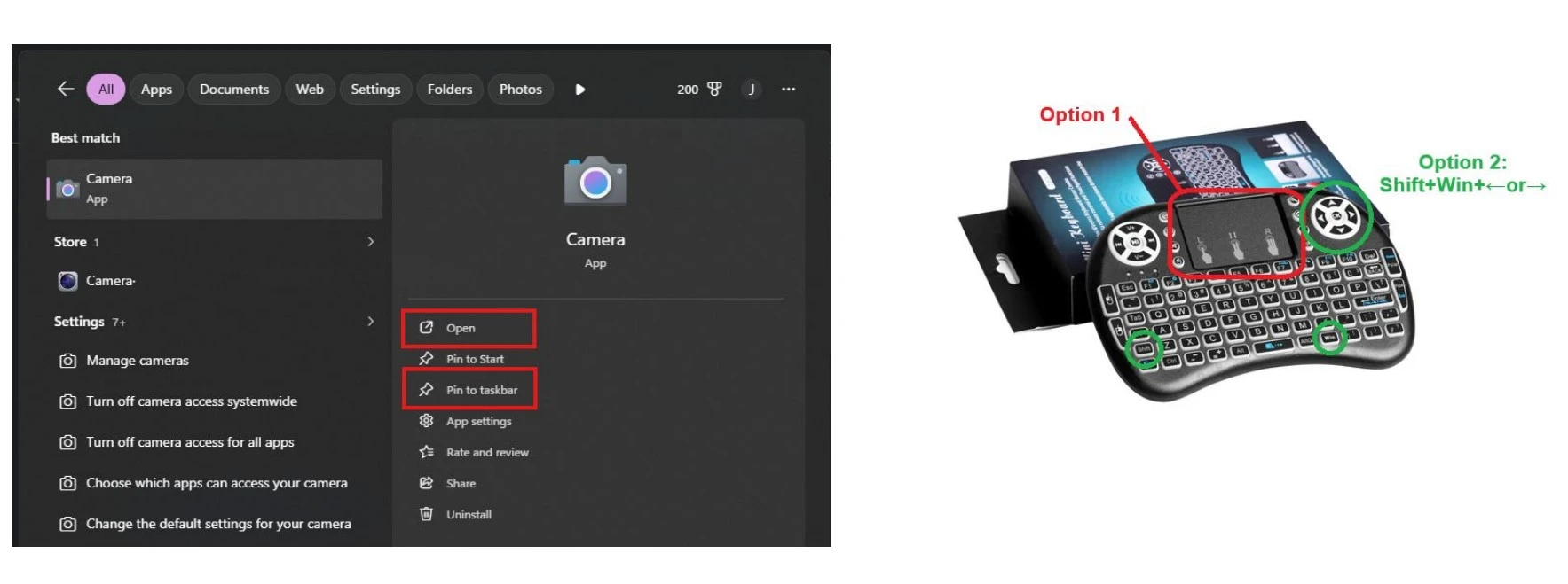
7: Open the Camera on PC
Open the Camera live feed on the second monitor
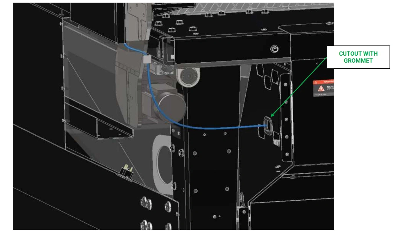
8: Routing the Light
The seventh step in the assembly process is to route the light cable through the enclosure to the electronics box.
Materials
Parts
- (1) Light Cable
Hardware
- None
Tools
- (Optional) 2.5mm Hex Key
Instructions
-
Following the mirrored cable management path as the camera USB cable, the light cable will branch down into the electrical cabinet for final installation.
NOTEIt is recommended to jog the Apollo’s gantry to the home position to visualize potential hook points for unmanaged wires. Once familiar with these points, you may move the gantry away to continue routing your light cable, being sure to avoid any hook points.
-
Route the remaining light cable down the wall in which your monitors are mounted into the corner panel of your Apollo’s lower enclosure.
WARNINGELECTRICAL SHOCK
-
Using the final cable tie mount from step 3, route the remaining cable towards the electrical cabinet, passing through the grommeted cutout.
NOTEIt may be necessary to remove the electrical cabinet’s cover to assist in routing the light cable.
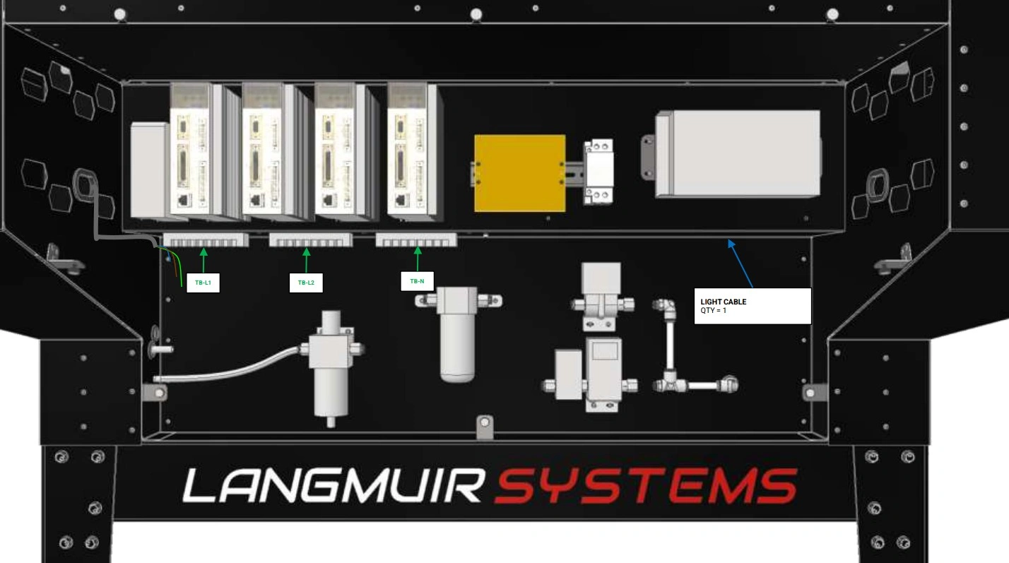
9: Wiring the Light
The eighth step in the assembly process is to route the light cable through the enclosure to the electronics box.
Materials
Parts
- (1) Light Cable
Hardware
- None
Tools
- #2 Phillips Head Screwdriver
- 2.5mm Hex Key
Instructions
- If not removed already, remove both panels covering the electrical cabinet of your Apollo.
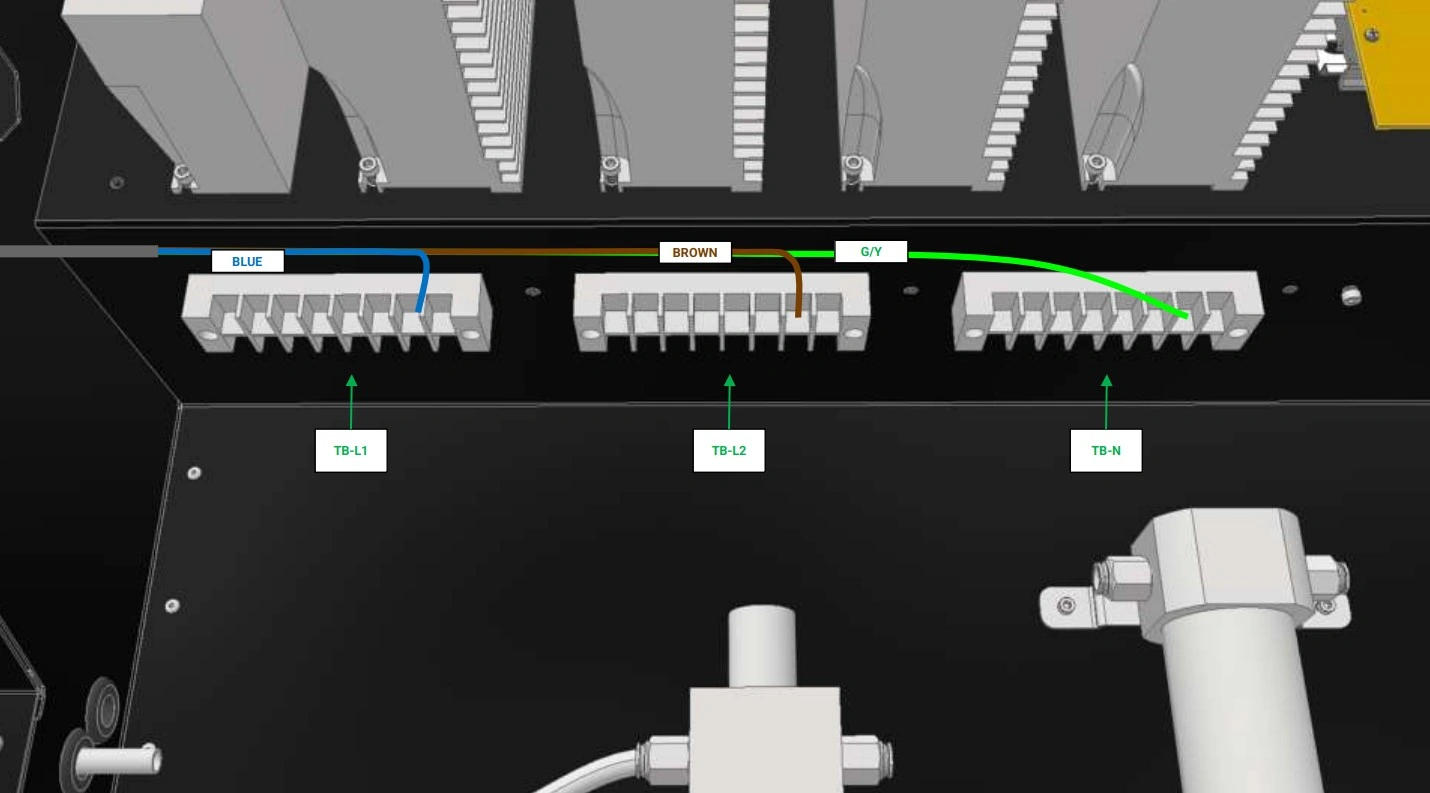
- Locate the three terminal blocks on the left hand side of the cabinet. From left to right, the terminal blocks are TB-L1, TB-L2, and Neutral (TB-N).
- Following the cable path shown, route the light cable across the enclosure to the terminal blocks.
- The outer sheath of the light cable may need to be stripped back further to allow enough wire length to connect the light to the terminal blocks.
Materials
Parts
- (1) Light Cable
Hardware
- None
Tools
- #2 Phillips Head Screwdriver
Instructions
- Remove the plastic covers from the terminal blocks.
- On each terminal Block, locate an open terminal and back out the screw.
- Wire the 10W Light cable as shown ensuring the proper wire is connected to the proper terminal block.
- Return the plastic covers back to the terminal blocks and re-install the cover for the electrical cabinet.
- Power on the machine and verify that the light is operational by flipping the switch located along the wire’s cable.
- You have completed the installation of the Light and Camera Kit.
Apollo laser glass door add-on
Images in this Guide
The assembly drawings and pictures included in this guide can be expanded to
full-screen and zoomed to provide more detail on a given step.
1: Install the Laser Safety Glass
The first step in the installation process is to fasten the safety glass to the door panel.
LASER SAFETY GLASS KIT : If you are installing the Laser Safety Glass Kit, follow the guide below. Otherwise, SKIP IT→
Materials
Parts
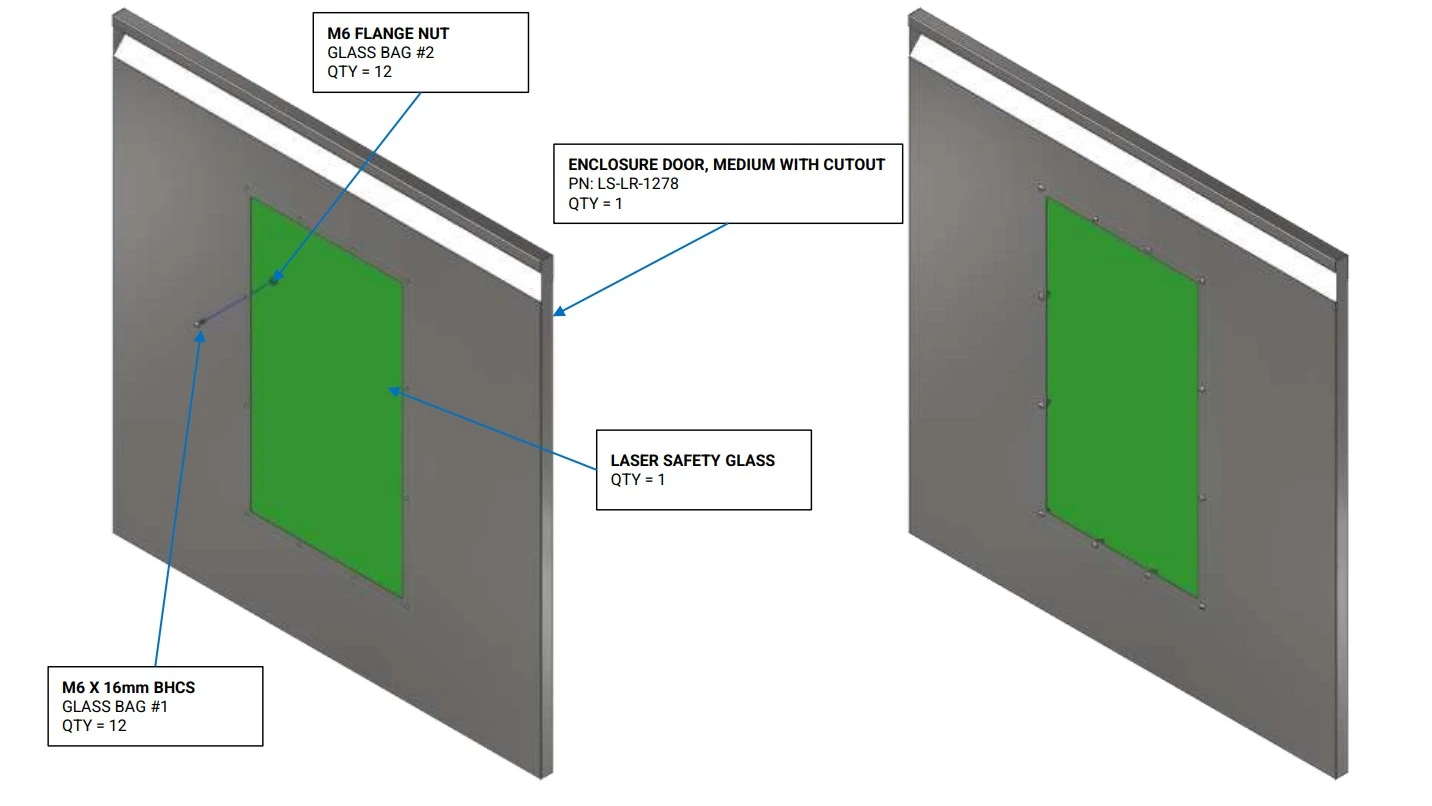
- (1) Enclosure Door, Medium with Cutout
- (1) Laser Safety Glass
Hardware
- (12) M6 Button Head Cap Screw
- (12) M6 Flange Nut
Tools
- 4mm Hex Key
Instructions
- Locate the Enclosure Door, Medium with Cutout and the Laser Safety Glass.
- Using the hardware shown, secure the laser safety glass to the door.
- Repeat step A2 for all bolts and nuts.
- Install the completed door onto your enclosure, replacing the Enclosure Door, Large that came with the standard upper enclosure.
- Repeat steps A1-A4 for all doors purchased with laser safety glass.
Apollo material transfer installation
Images in this Guide
The assembly drawings and pictures included in this guide can be expanded to
full-screen and zoomed to provide more detail on a given step.
1: Install the Transfer Balls
The first and only step is to install the transfer balls.
MATERIAL TRANSFER BALL KIT : If you are installing the Material Transfer Ball Kit, follow the guide below. Otherwise, SKIP IT→
Materials
Parts
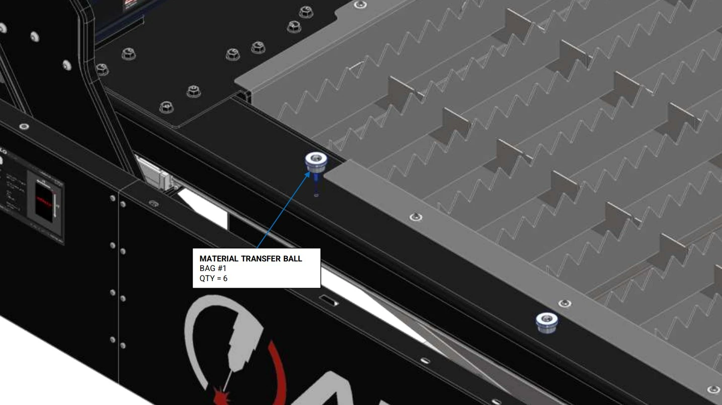
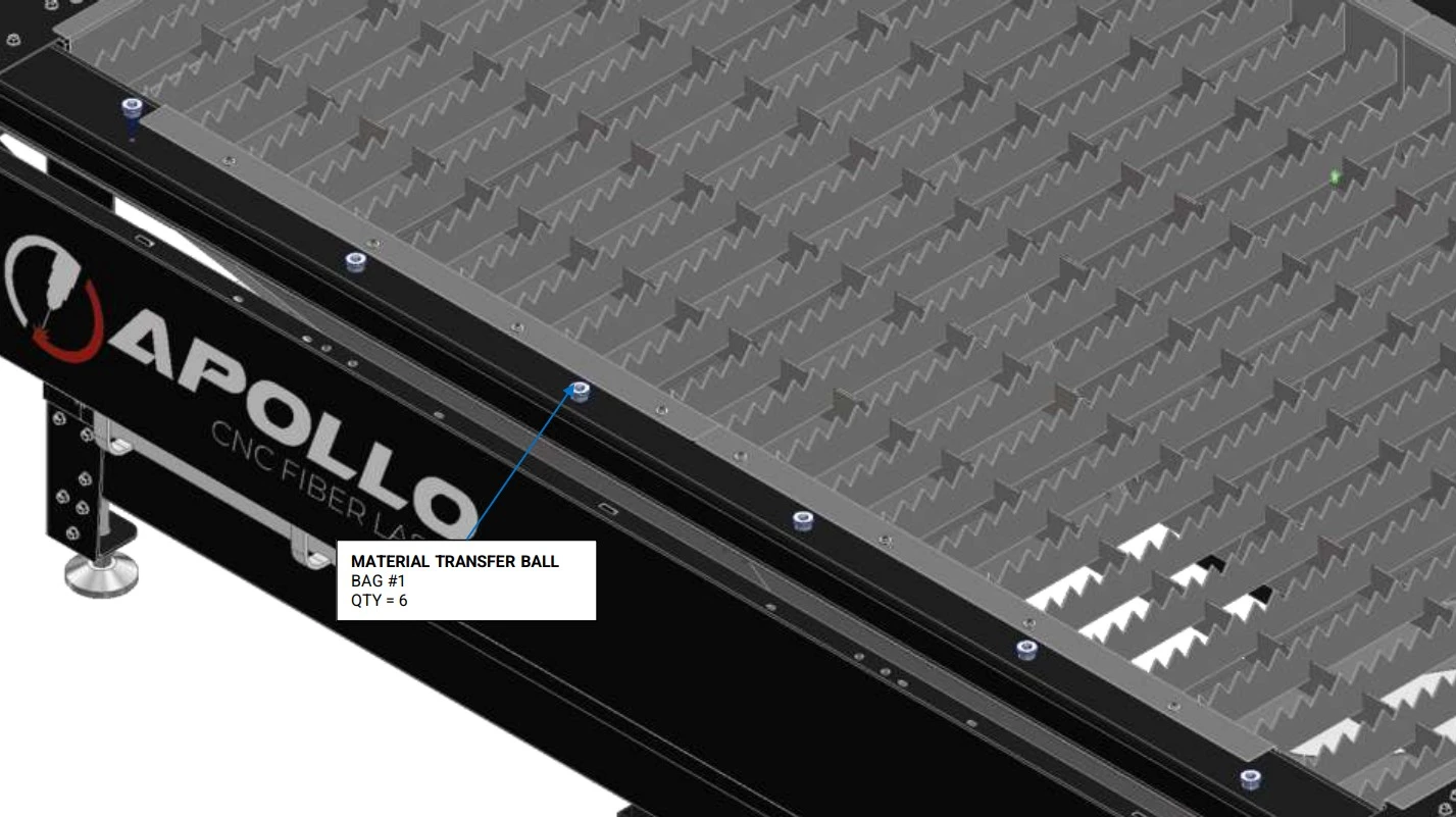
- (6) Material Transfer Ball
Hardware
- None
Tools
- None
Instructions
- Locate the Material Transfer Balls that came with your add-on kit.
- On the operator side of the machine, locate the threaded holes the run down the length of the curbed.
- Install the transfer balls into the threaded holes until hand tight.
Materials
Parts
- (6) Material Transfer Ball
Hardware
- None
Tools
- None
Instructions
- Repeat the installation process outlined in A1-A3 for all remaining transfer balls.
Quick Start Operation Guide
Images in this Guide
The assembly drawings and pictures included in this guide can be expanded to
full-screen and zoomed to provide more detail on a given step.
1: Preparing a Program
The first step is to process a cut file to load into Laser Control.
Materials
Parts
- None
Hardware
- None
Tools
- CAD Software
Instructions
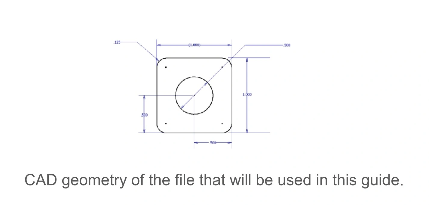
- It is recommended to create a simple small part to use as a trial cut to dial in the cut parameters on the Apollo CNC Fiber Laser.
- The file being used in this example is a simple 1 inch by 1 inch square with ⅛ inch corner rounds and a ½ inch hole in the center of the part.
- Once your trial part is modeled, a .dxf file needs to be created.
Materials
Parts
- None
Hardware
- None
Tools
- SheetCam Software
- SheetCam Laser processing tool
Instructions
NOTE
Langmuir Systems recommends the use of SheetCAM for processing g-code files. For information on how to navigate through and fully utilize SheetCAM, check out some resources HERE→
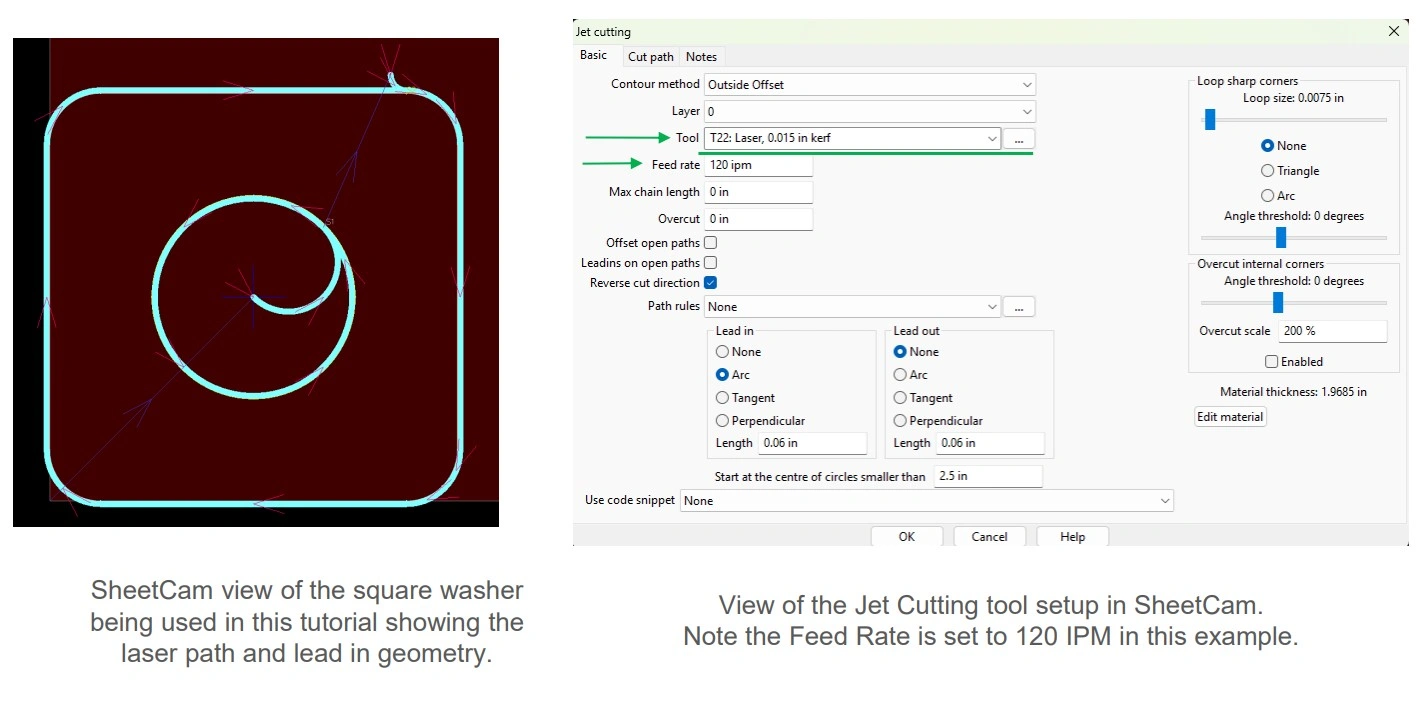
- Import part to be cut into SheetCam.
- Create a new Jet Cutting operation. Be sure to select the laser tool from the Tool drop down to process the file so the Apollo CNC Fiber Laser can execute the g-code properly.
NOTEIn this example, an outside offset with an arc lead in and no lead out was selected. Note the material thickness to be cut and enter the speed in the Jet Cutting Operation as Laser Control can use the speed from the SheetCam file or the material table in Laser Control.
- Run the post processor and save the .tap file in a location that can be accessed by Laser Control.
Materials
Parts
- None
Hardware
- None
Tools
- LaserControl
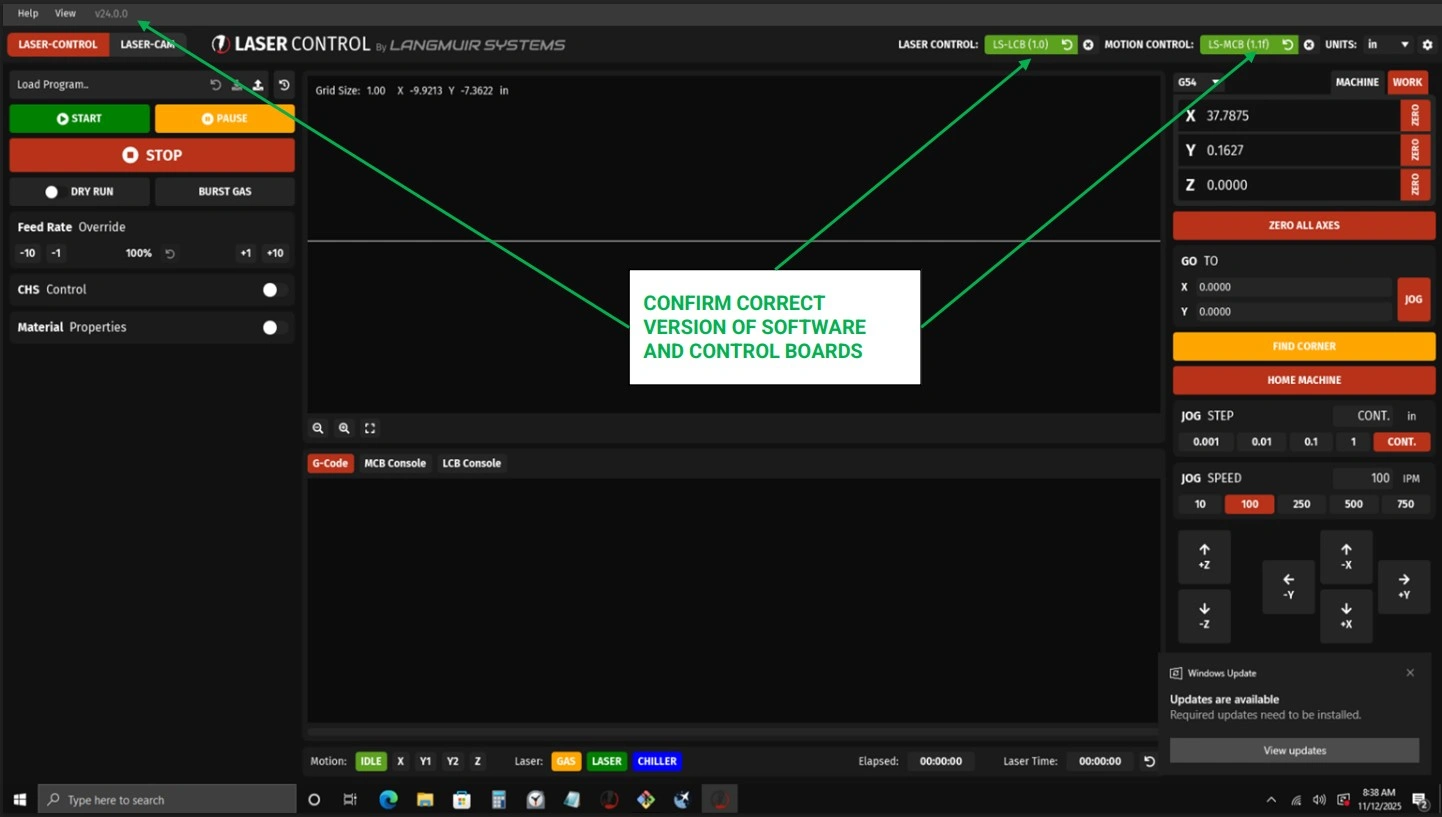
Instructions
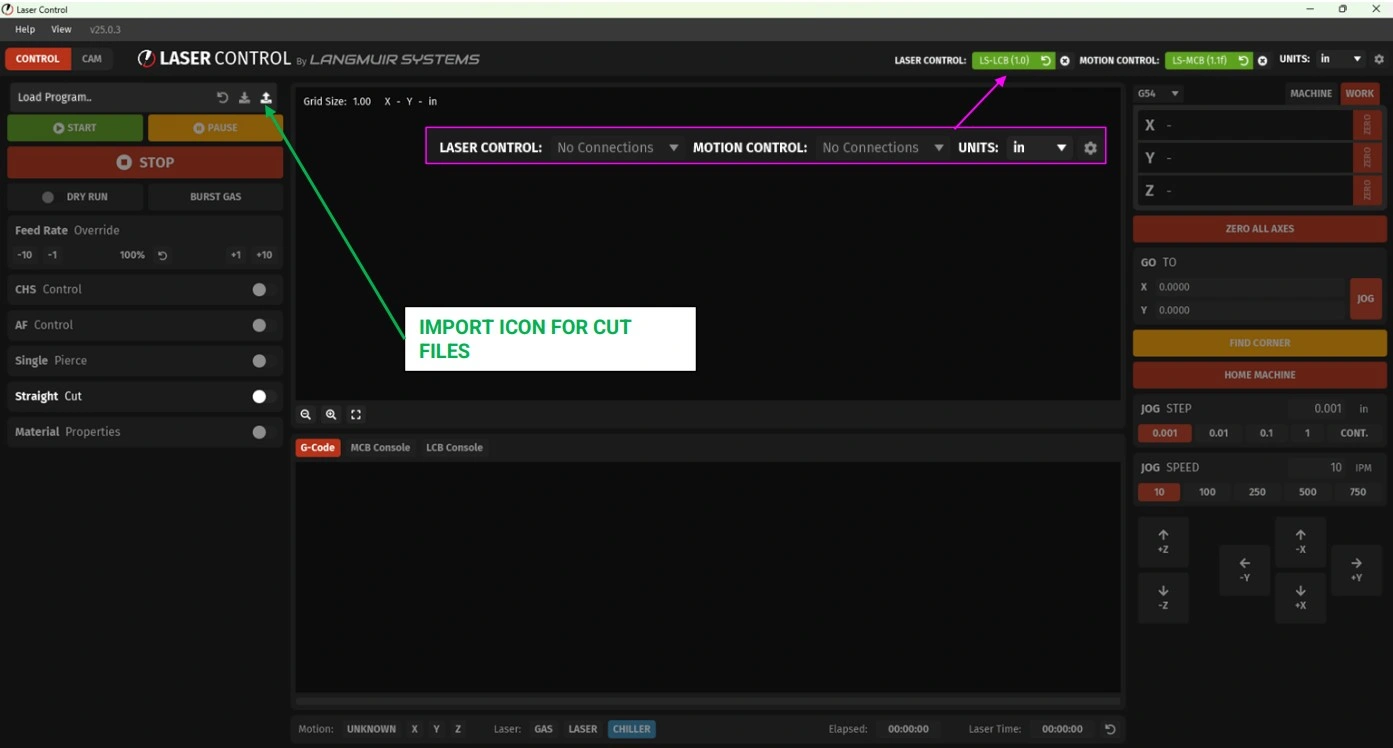
- In the upper right hand corner of Laser Control, ensure that Laser Control and Motion Control are connected. If they are not connected, choose the boards in the drop down menus.
- Using the icon highlighted with the green arrow, load the .tap file. Once loaded, an image of the cut file will be loaded in the upper window of Laser Control.
Materials
Parts
- None
Hardware
- None
Tools
- LaserControl
Instructions
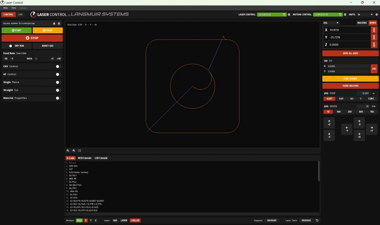
- If following these instructions your Laser Control screen should look like the image above at this point. If you are using your own file, your Laser Control screen should look similar but with your geometry loaded in the viewer window.
2: Preparing Apollo
The second step is to prepare the Apollo to make your first cut.
Materials
Parts
- None
Hardware
- None
Tools
- None
Instructions
- Load a sheet of material onto the Apollo CNC Fiber Laser ensuring that it sits across the slata and does not tip or fall through. Note the material type and thickness as it will change the speed of cut, focal point, nozzle, gas type and gas pressure to be used.
- Jog the laser head over the material to be cut ensuring the laser is not over any hole in the material, if applicable.
Materials
Parts
- None
Hardware
- None
Tools
- None
Instructions
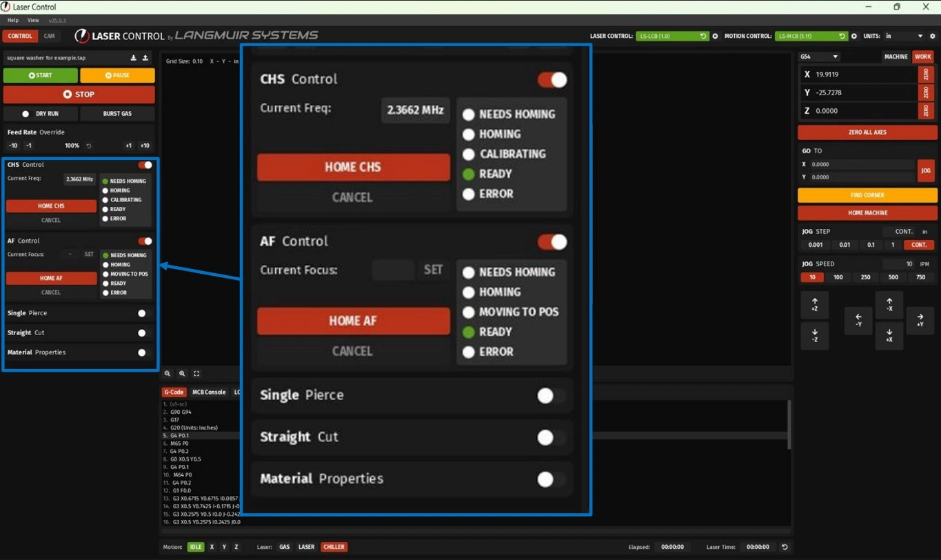
- Open the CHS Control tab by touching the slider widget to the right of the CHS Control text.
-
Home the CHS by clicking the Home CHS button. A status bar will appear showing the progress of CHS homing. CHS homing must be completed before proceeding to the next step.
NOTEIf using a manual focus head, skip Steps B3 & B4. Proceed to step B5.
If using an autofocus head, proceed to step B3. - Open the AF Control tab by touching the slider widget to the right of the AF Control text.
- Home the AF by clicking the Home AF button and wait for homing to be completed.
- Close both the CHS Control and AF Control tab(s).
3: Set Cut Parameters
The third step is to set your cut parameters on Laser Control.
Materials
Parts
- None
Hardware
- None
Tools
- None
Instructions
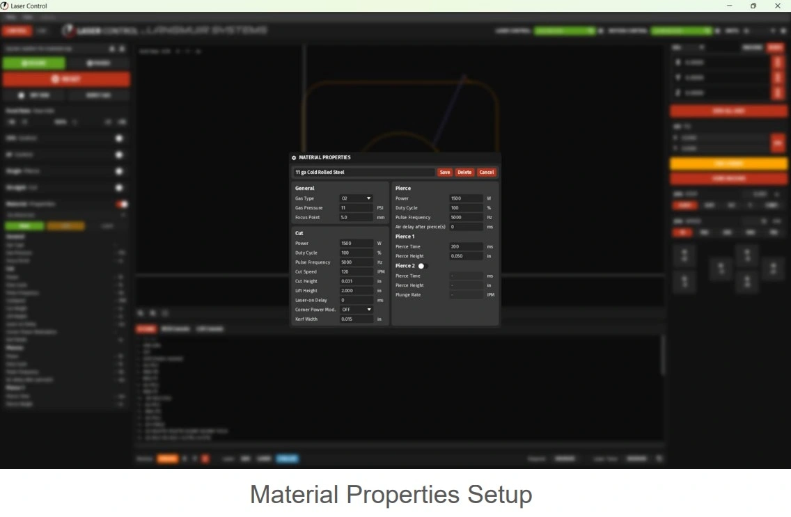
- Open the Material Properties tab by touching the slider widget to the right of the Material Property text.
- Click on the green “new” button. A material properties pop up window will appear.
-
Fill out the material properties window. In this example, 11 gauge carbon steel is being used and the default material properties are below:
Section Parameter Value General Gas Type O2 Gas Pressure 11 PSI Focus Point 5.0 mm Power 1500 W Pierce Duty Cycle 100 % Pulse Frequency 5000 Hz Air Delay After Pierce 0 ms Cut Power 1500 W Duty Cycle 100 % Pulse Frequency 5000 Hz Cut Speed 120 IPM Cut Height 0.031 in Lift Height 2.000 in Laser-on Delay 0 ms Corner Power Mod. OFF Pierce 1 Pierce Time 200 ms Pierce Height 0.050 in Kerf Width 0.015 in Pierce 2 Status OFF - Name the material property and click the save button
- Click the blue “load” button
- Ensure the proper nozzle is installed. If a nozzle change is needed, unscrew the nozzle by turning the nozzle counterclockwise to remove it from the laser head. Locate the desired nozzle and install by turning the nozzle clockwise.
NOTEThe Apollo CNC Fiber Laser shipps with a Double 1.5mm from the factory. If this nozzle is going to be used, please remove the blue protective tape from the bottom of the nozzle. Future nozzle changes need to be performed with caution as the nozzle will become hot with use. Ensure that the nozzle has had proper time to cool off prior to touching or removing the nozzle.
- If using a manual focus head Proceed to Step B. If using an autofocus head proceed to Step C.
Materials
Parts
- None
Hardware
- None
Tools
- Size ? Wrench
- Size ? Wrench
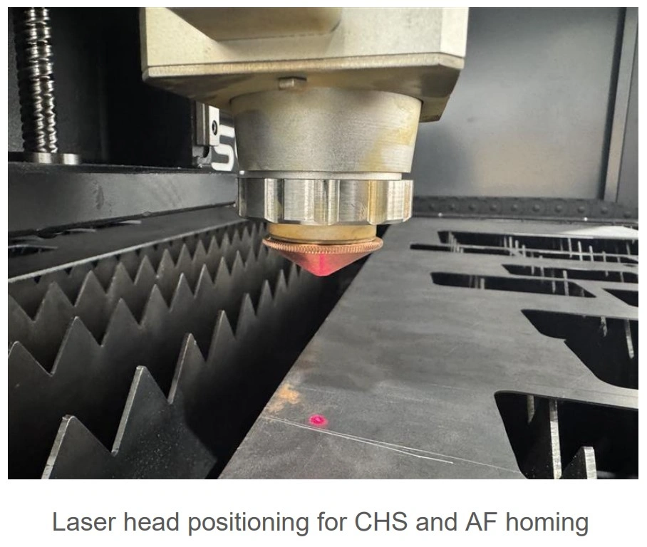
Instructions
NOTE
If using an autofocus head, skip this step and proceed to step C.
CAUTION: DO NOT loosen the scale (outer ring) of the focal adjustment assembly.
- Loosen the locknut labeled B1 by rotating it counterclockwise.
- Adjust the focal distance by rotating the knob (inner disk) labeled B2 so the indicator line aligns with the desired marking on the scale.
- Once the focus position is properly set, tighten the locknut labeled B1 by rotating it clockwise.
Materials
Parts
- None
Hardware
- None
Tools
- None
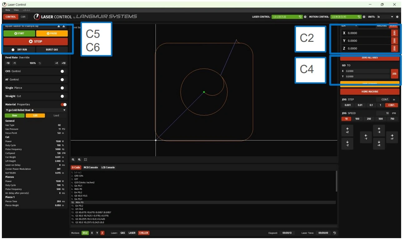
Instructions
- Confirm the position of the laser is over the material to be cut.
- Zero both the X and Y axis by clicking the zero buttons by the X and Y axis position in the upper right hand corner of the Laser Control window. The crosshairs will now be the X 0.000 and Y 0.000 work location.
- Jog the machine in both the X direction and Y direction noting the laser location over the sheet and the graphical display to ensure the profile will be cut from a solid piece of material.
- Once the profile has been confirmed, under the Go To box, ensure that X and Y are both set to 0.000, click the Jog button to return back to the work zero location.
- In the upper left hand corner of Laser Control, select the Dry run button. This will run the program without firing the laser.
- Click the start button to run the program and note the laser position and speed while performing the dry run. This is done to ensure that the machine moves as intended in the area intended to be cut.
- Repeat the above steps to adjust the cut location or speeds as needed.
- Once the desired location and speed has been achieved, click the Dry Run button again to deactivate.
WARNING
If LaserControl resets or the system is powered down, you MUST re-establish the zero position before continuing operation.
Failure to reset the zero potions can result in the following: Incorrect machine movement, Loss of positional accuracy, and Damage to the machine or cutting material. Always perform a "Zero All Axes" command after restarting LaserControl or powering the machine on. This step ensures the system has a correct reference point for all movement and cutting operations.
4: Prepare The Laser System
The fourth step is to prepare the laser head and source for cutting.
Materials
Parts
- Laser Ignition Key
Hardware
- None
Tools
- None
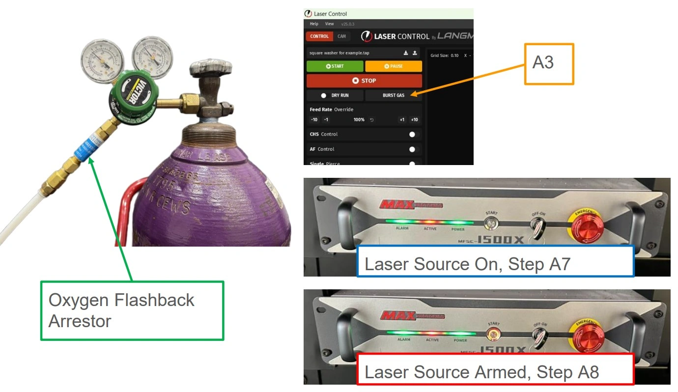
Instructions
WARNING
When using compressed oxygen cylinders, an oxygen flashback arrestor must be used to prevent flames from traveling into the cylinder in the event of accidental ignition of the gas line.
-
Turn on the appropriate gas source and set the pressure at the regulator on the gas bottle. In this example, Oxygen is required and will be turned on.
- The Oxygen system, if used, should be set between 50 psi and 75 psi. The final pressure is set by a valve in the Apollo gas system.
- The Nitrogen system, if used, needs to be set at the regulator per the cut chart.
- If shop air is being used, it is connected through the Nitrogen port and the air pressure needs to be set by a regulator in your air system.
- Turn on the chiller and let the temperature stabilize. While performing the next steps this should be completed.
- On Laser Control, Click the Burst Gas button in the upper left hand corner. You should hear and feel the gas being pushed through the nozzle. This is a purge step to ensure the assist gas is present when making the first cut.
- Replace any doors that were removed to load material, change nozzle or to set part placement.
- If Installed, ensure ventilation equipment is powered on and actively cycling air.
- Locate the Laser Ignition Key provided in the hardware box.
- Turn the key on the Apollo CNC Fiber Laser to the ON position.
WARNINGPERSONAL PROTECTIVE EQUIPMENTNOTEClass 4 lasers produce radiation at a level that can cause blindness without proper protective equipment. Before continuing, make sure that correct PPE is available and being worn at all times.
- Ensuring that proper PPE is being utilized, press the START button on the laser source. A red ring LED will light up around the START button. This arms the laser system and is the last step to be performed before firing the laser.
5: Cutting The Part
The fifth step in the quick start guide is to make your first cut.
Materials
Parts
- None
Hardware
- None
Tools
- None
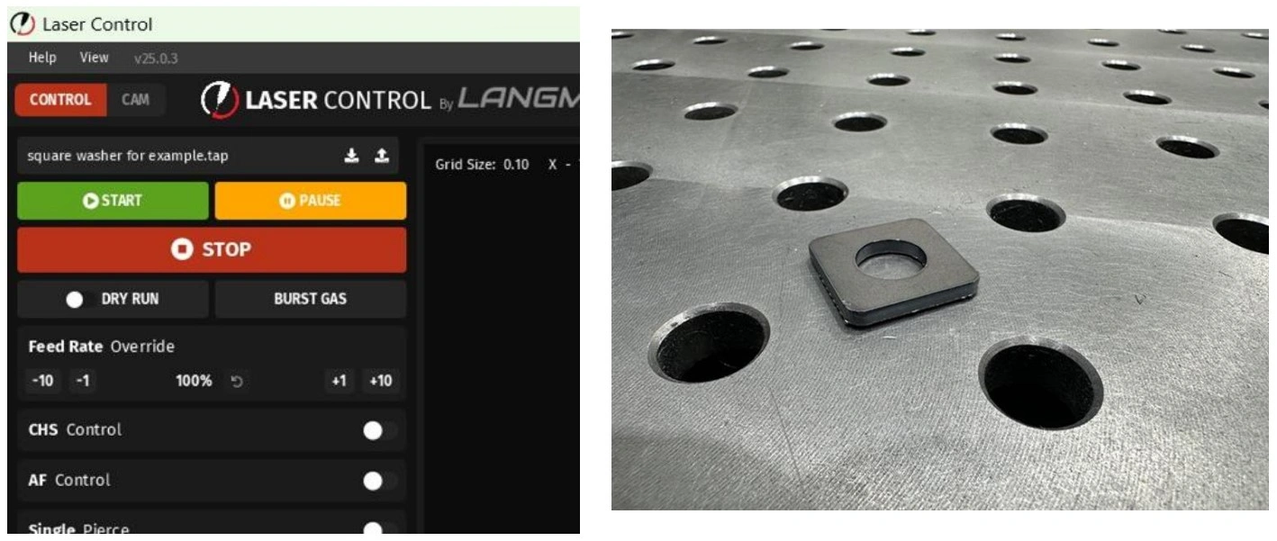
Instructions
WARNING
PERSONAL PROTECTIVE EQUIPMENT
NOTE
Class 4 lasers produce radiation at a level that can cause blindness without proper protective equipment. Before continuing, make sure that correct PPE is available and being worn at all times.
Parts cut from the laser are hot. Use appropriate part retrieval tool to avoid burns.
- In Laser Control press the green START button.
- Once the part is cut, if smaller than the slats can support, retrieve the part from the wagon.
- Analyze the cut quality and make adjustments to the speed, focal point and/or gas pressure to achieve the cut quality desired.
- Record the cut parameters that produced an acceptable cut for a starting point for future cuts.
6: Shutting Down Apollo
The sixth step in the quick start guide is to shut down the Apollo CNC Fiber Laser.
Materials
Parts
- None
Hardware
- None
Tools
- None
Instructions
- Turn off any gas supply to the Apollo CNC Fiber Laser.
- Turn off the main power to the Apollo CNC Fiber Laser. This will also turn off the laser source.
- Turn off the fume extractor, if using a fume extraction fan.
- Turn off the CPU. Power down the CPU by shutting down in the start menu.
- Turn off the chiller.
- Inspect the area under the Apollo CNC Fiber Laser to ensure no chiller leaks are present. If a leak is found, ensure the push to connect fitting is securely connected or replace damaged tubing.
- Empty debris from the part retrieval wagon. Laser cutting produces debris in the form of slugs and dust. By keeping the wagon clean, part retrieval is easier and will not foul magnets or other part retrieval tools as quickly.
CUTTING parameters for APOLLO CNC FIBER LASER
Carbon Steel
Thickness
(in)
(in)
Gauge
Speed
(IPM)
(IPM)
Focal Position
(mm)
(mm)
Focal Position
(in)
(in)
Cutting Height
(in)
(in)
Gas
Nozzle Type
Air Pressure
(PSI)
(PSI)
Laser Power
(W)
(W)
Cutting
Frequency (Hz)
Frequency (Hz)
Duty Cycle
(%)
(%)
0.039”
20
1319
0
0
0.02
N2
Single 1.0
203
1500
5000
100
0.079”
14
374
-0.25
-0.010
0.02
N2
Single 1.5
203
1500
5000
100
0.157”
8
98
5.0
0.197
0.031
O2
Double 1.0
11
1500
5000
100
0.197”
6
75
2.5
0.098
0.059
O2
Double 3.0
11
1500
5000
100
0.236”
3
67
2.5
0.098
0.059
O2
Double 3.0
11
1500
5000
100
0.315”
—
47
2.5
0.098
0.059
O2
Double 3.0
11
1500
5000
100
0.394”
—
37
2.5
0.098
0.059
O2
Double 3.0
11
1500
5000
100
0.472”
—
33
2.5
0.098
0.059
O2
Double 3.0
11
1500
5000
100
0.551”
—
26
2.5
0.098
0.059
O2
Double 4.0
11
1500
5000
100
Stainless Steel
Thickness
(in)
(in)
Gauge
Speed
(IPM)
(IPM)
Focal Position
(mm)
(mm)
Focal Position
(in)
(in)
Cutting Height
(in)
(in)
Gas
Nozzle Type
Air Pressure
(PSI)
(PSI)
Laser Power
(W)
(W)
Cutting
Frequency (Hz)
Frequency (Hz)
Duty Cycle
(%)
(%)
0.039”
20
1319
0
0
0.02
N2
Single 1.0
203
1500
5000
100
0.079”
14
374
-0.25
-0.010
0.02
N2
Single 1.5
203
1500
5000
100
0.118”
11
171
-1.25
-0.049
0.02
N2
Single 2.0
203
1500
5000
100
0.157”
8
87
-2.25
-0.089
0.02
N2
Single 3.0
203
1500
5000
100
0.197”
6
67
-3.25
-0.128
0.02
N2
Single 3.5
203
1500
5000
100
0.236”
3
43
-4.75
-0.187
0.02
N2
Single 3.5
203
1500
5000
100
Aluminum
Thickness
(in)
(in)
Gauge
Speed
(IPM)
(IPM)
Focal Position
(mm)
(mm)
Focal Position
(in)
(in)
Cutting Height
(in)
(in)
Gas
Nozzle Type
Air Pressure
(PSI)
(PSI)
Laser Power
(W)
(W)
Cutting
Frequency (Hz)
Frequency (Hz)
Duty Cycle
(%)
(%)
0.039”
20
1024
0
0
0.02
Air
Single 1.0
203
1500
5000
100
0.079”
14
335
-0.25
-0.010
0.02
Air
Single 1.5
203
1500
5000
100
0.118”
11
157
-0.25
-0.010
0.02
Air
Single 2.0
203
1500
5000
100
0.157”
8
83
-1.25
-0.049
0.02
Air
Single 3.0
203
1500
5000
100
0.197”
6
35
-1.5
-0.059
0.02
Air
Single 3.5
203
1500
5000
100
Brass
Thickness
(in)
(in)
Gauge
Speed
(IPM)
(IPM)
Focal Position
(mm)
(mm)
Focal Position
(in)
(in)
Cutting Height
(in)
(in)
Gas
Nozzle Type
Air Pressure
(PSI)
(PSI)
Laser Power
(W)
(W)
Cutting
Frequency (Hz)
Frequency (Hz)
Duty Cycle
(%)
(%)
0.039”
20
965
0
0
0.02
Air
Single 1.0
203
1500
5000
100
0.079”
14
295
-0.25
-0.010
0.02
Air
Single 1.5
203
1500
5000
100
0.118”
11
112
-0.25
-0.010
0.02
Air
Single 2.0
203
1500
5000
100
0.157”
8
63
-1.25
-0.049
0.02
Air
Single 3.0
203
1500
5000
100