CrossFire PRO MAX Assembly Guide
Safety
When used correctly, the Langmuir Systems Crossfire CNC Plasma Table will offer you years of safe operation. However, like all other automated and industrial type machinery, there are important safety considerations and precautions that must be followed in order to avoid injury. Study these safety warnings carefully before assembling and using your machine.

ELECTRIC SHOCK
Electric shock can cause serious injury or death. This machine requires the use of high voltage electricity to operate. To avoid injury, always adhere to the following precautions:
- Never touch bare wires/buses/connections or components that are carrying electricity.
- Repair or replace all worn or damaged components. Turn off power to machine and plasma cutter when making repairs.
- Install and maintain equipment in accordance with the National Electric Code (NEC)
- If you have limited electrical knowledge/experience, hire a certified electrician to perform all electrical work.

FIRE AND EXPLOSION
Fire and explosion can be caused by the airborne sparks and slag igniting a nearby flammable material. Electrical fires can be caused if the machine is assembled or used incorrectly. To avoid injury, always adhere to the following precautions:
- Never operate the machine in the vicinity of flammable materials or where there is volatile and combustible fumes in the air.
- Do not use the machine to cut materials or parts that have previously contained fuel or flammable substance of any kind such as gas tanks.
- Always keep a fire extinguisher nearby in case of emergency.
- Never operate the machine in a poorly ventilated area.

AUTOMATIC OPERATION
The machine may operate at any time, automatically, and without warning. To avoid injury, always adhere to the following precautions:
- Acquire sufficient training before operating the machine.
- Never place any part of your body in direct contact with areas of the machine that can pinch and crush when powered on. Assume that if the machine is powered, it may move at any time.
- Keep area clear of bystanders, make sure that no one but the person operating the machine has access to the computer controls.

HAZARDOUS FUMES
Gases and fumes produced during the plasma cutting process can be hazardous to your health. To avoid injury, always adhere to the following precautions:
- Keep all fumes and gases from the area in which you breathe. Never operate the machine in an area with minimal or no ventilation. Use fans and blowers to remove fumes and gases from the work area.
- If ventilation is poor, use an air-supplied respirator system.
- The type of fumes and hazard level depends greatly on the type of metal being cut. Before cutting, consult the Material Data Safety Sheet (MSDS) for specific guidelines on the type and hazard level of the fumes produced during cutting.
- Never cut materials that has been coated with paint, oil, grease, or solvents.

ULTRAVIOLET AND INFRARED RADIATION
The plasma cutter produces high intensity ultraviolet and infrared light that can damage your eyes and skin. To avoid injury, always adhere to the following precautions:
- Never operate the machine without sufficient eye protection. Consult the user manual for your plasma cutter to determine the minimum protective shade required for the amperage of your machine. Alternatively, consult ANSI/ASC Z49.1.
- Wear gloves and suitable clothing to protect your skin at all times.
- Always alert bystanders before you begin cutting. Bystanders in the immediate vicinity must wear suitable eye and skin protection. Use welding screens whenever possible.

SPARKS AND AIRBORNE DEBRIS
Plasma cutting creates airborne sparks and debris that can cause eye injuries. To avoid injury, always adhere to the following precautions:
- Always wear suitable eye protection when operating the machine. Eye protection should follow the guidelines established in ANSI Z87.1.
- Ensure that all bystanders in the immediate vicinity are wearing suitable eye protection.

PINCH AND CRUSH POINTS
This machine can create pinch points while in motion during normal operations. To avoid injury, always adhere to the following precautions:
- Do not touch any part of the machine when it is moving under power.
- Be aware of all areas of the machine that could potentially be a pinching hazard, such as bearings, lead screws, lead nuts, and slides.
- Never make repairs to the machine when the machine is powered on.

HOT MATERIALS
The plasma cutting process uses extremely high temperatures to cut metal. As a result, the material can be very hot after cutting which can cause burns. To avoid injury, always adhere to the following precautions:
- Always assume that metal resting on the machine is hot enough to cause severe burns.
- Always allow the metal to sufficiently cool before handling. Use a bucket of water to cool down part before handling with bare hands.
- Never handle hot metal with bare hands. Use gloves or tongs to remove material from the machine.
WARNING
This product can expose you to chemicals which are known to the State of California to cause
cancer, birth defects or other reproductive harm. For more information go to www.P65Warnings.ca.gov.
CrossFire PRO MAX Assembly
The Langmuir Systems CrossFire PRO MAX ships partially assembled. Therefore, this section serves to provide all of the pertinent information and instructions needed to fully assemble your new machine.
Images in this Guide
The assembly drawings and pictures included in this guide can be expanded to full-screen and zoomed to provide more detail on a given step.
0: Unboxing
The CrossFire ProMAX is delivered in 3 individual boxes to make the kit manageable to ship. These boxes are labeled with their contents but a more in-depth description of whats inside is provided here. Please use this as a reference for the rest of the assembly.
ProMAX Box #1
- (11) Steel Frame Tubes
- (3) Lead Screws
- (8) Slat Holders
- (1) Cable Support Tube
ProMAX Box #2
- (1) CrossFire ProMAX Electronics
- (2) Carriage Weldments
- (1) Z-Axis Assembly Box
- (1) Hardware Box
- (4) Bearing Block Flange Assemblies
- (1) Miscellaneous Box
- (1) Stepper Motors Box
ProMAX Box #3
- (2) Water Table Halves
- (14) Steel Slats
- (1) Gussets Box
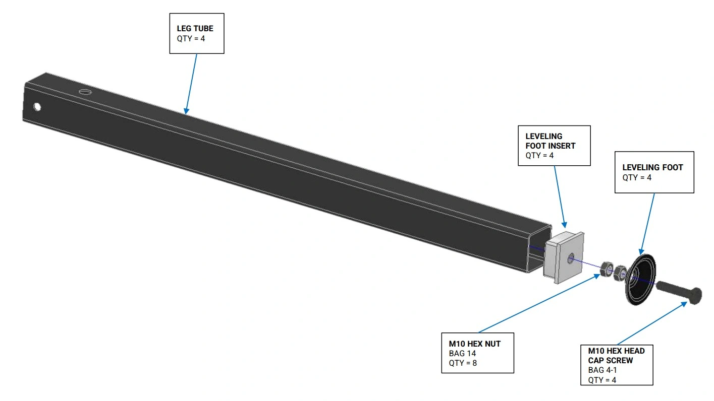
1: Install Leveling Feet
The first step in CrossFire ProMAX assembly is to install the leveling feet on your leg tubes.
Materials
Parts
- (4) Leg Tube (with and without mounting holes)
- (4) Leveling Foot Insert
- (4) Leveling Foot
Hardware
- (4) Bag 4-1 M10 HEX HEAD CAP SCREW
- (8) Bag 14 HEX NUT, 10MM X 1.5mm, ZINC PLATED
Tools
- Soft Faced Hammer or Mallet
- (2) 17mm wrenches
Instructions
- Insert the Bag 4-1 M10 Cap Screw into the hole of Leveling Foot. Screw one of the Bag 14 M10 Hex Nuts onto the M10 screw. Fully tighten the nut.
- Screw the second Bag 14 M10 Hex Nut onto the screw with approximately 1” gap between it and the first nut.
- Tap the Leveling Foot Insert into the bottom end of the Leg Tube. Make sure the insert is fully seated. Note that the leveling insert shipped with your machine will look different than what is shown in the image.
- Screw the leveling foot assembly into the Leveling Foot Insert until the nut contacts the leveling insert.
- Repeat steps for the other 3 leg assemblies.
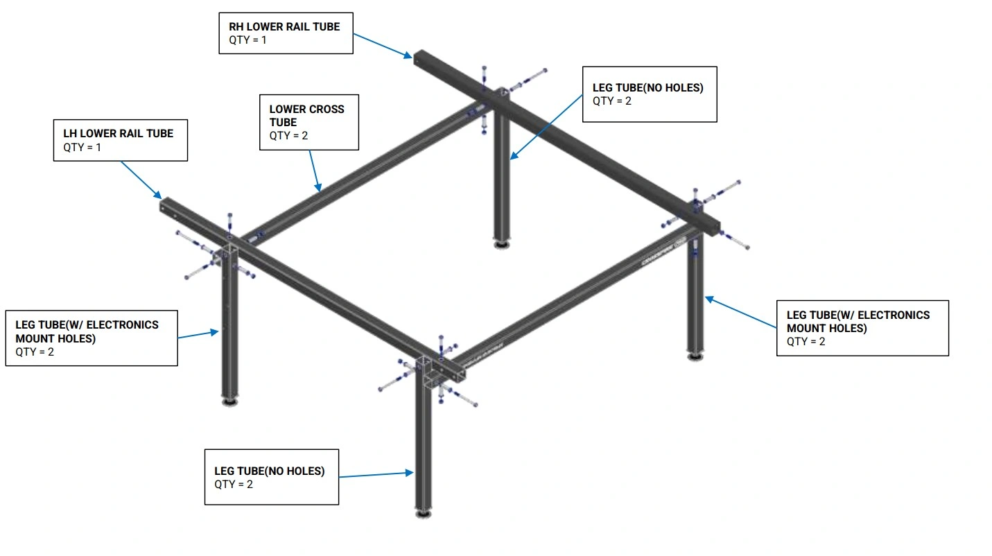
2: Frame Assembly
Gather all black frame tubes on a large work surface and assemble the frame of the CrossFire ProMAX.
Materials
Parts
- (2) Leg Tube (with electronics mounting holes)
- (2) Leg Tube (without mounting holes)
- (2) Lower Cross Tube (with Langmuir Systems and CrossFire ProMAX printing)
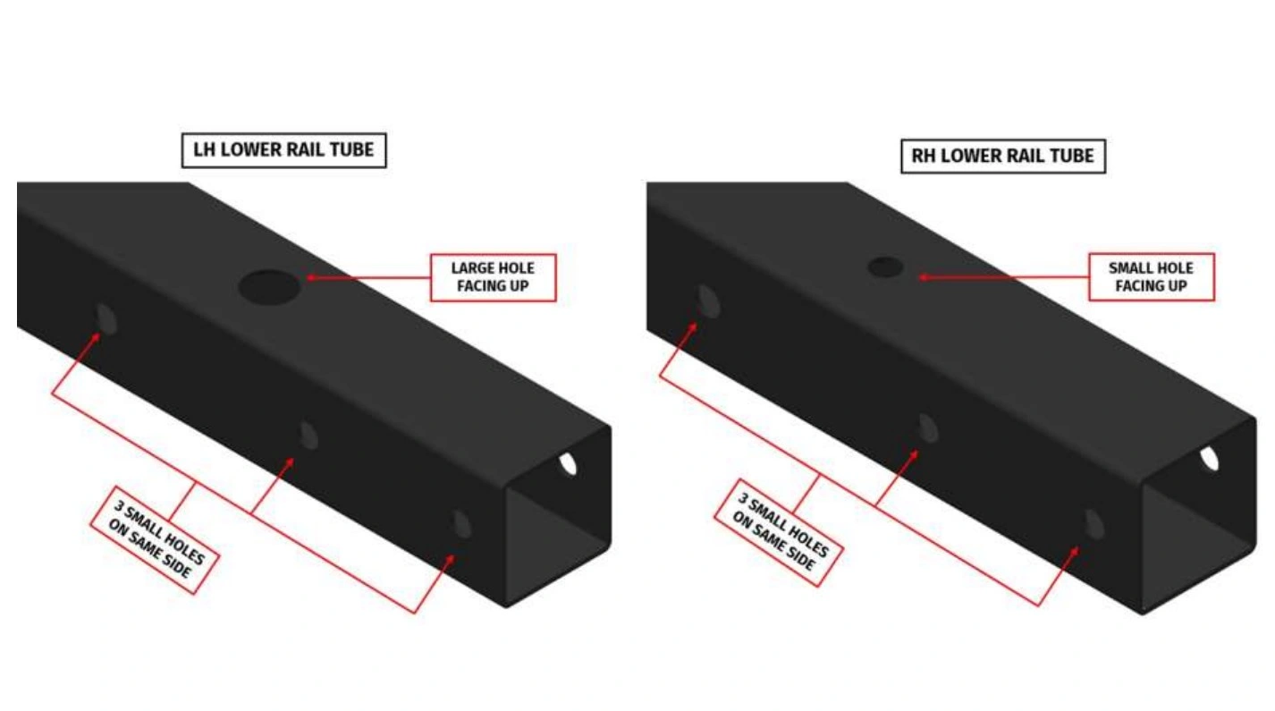
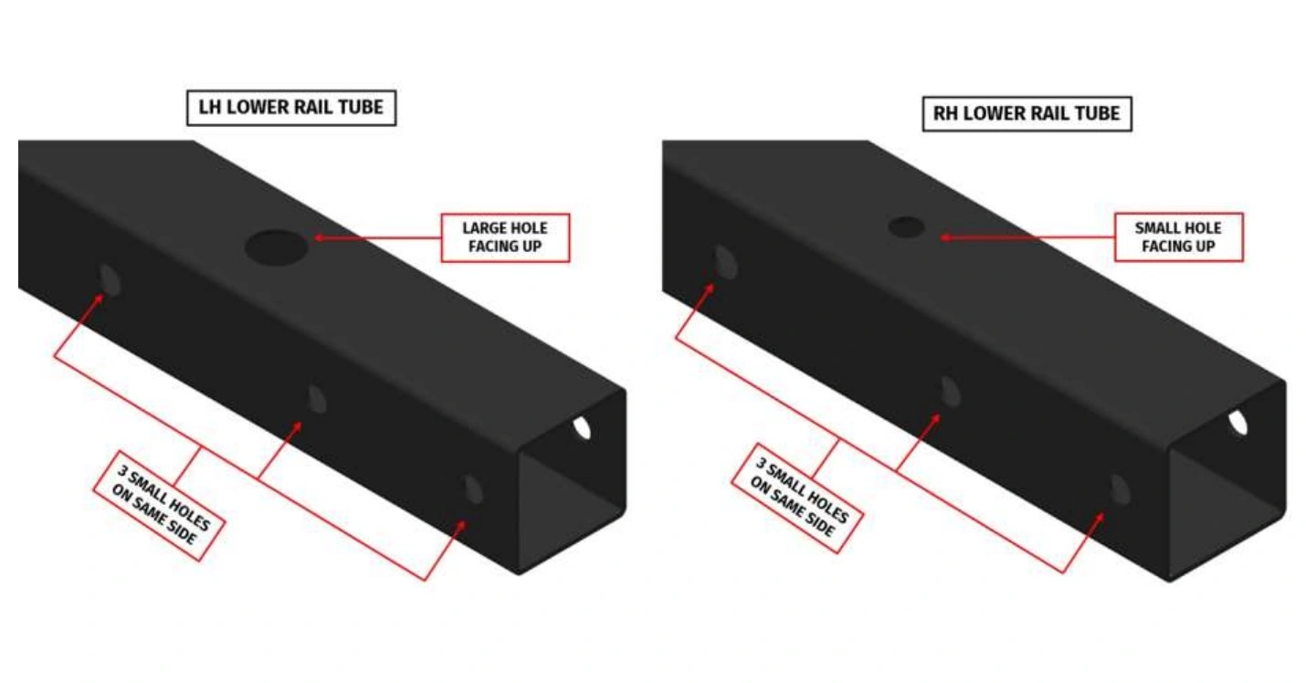
- (1) RH Lower Rail Tube
- (1) LH Lower Rail Tube
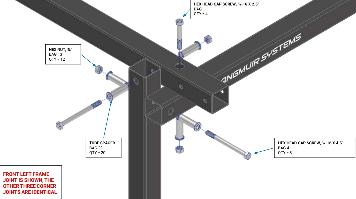
Hardware
- (8) Bag 4 HEX HEAD CAP SCREW, 3/8-16 X 4.5
- (4) Bag 1 HEX HEAD CAP SCREW, 3/8-16 X 2.5
- (12) Bag 13 HEX NUT, 3/8”
- (20) Bag 29 Tube Spacer
Tools
- 9/16" Wrench
- Ratchet with 9/16" Socket
Instructions
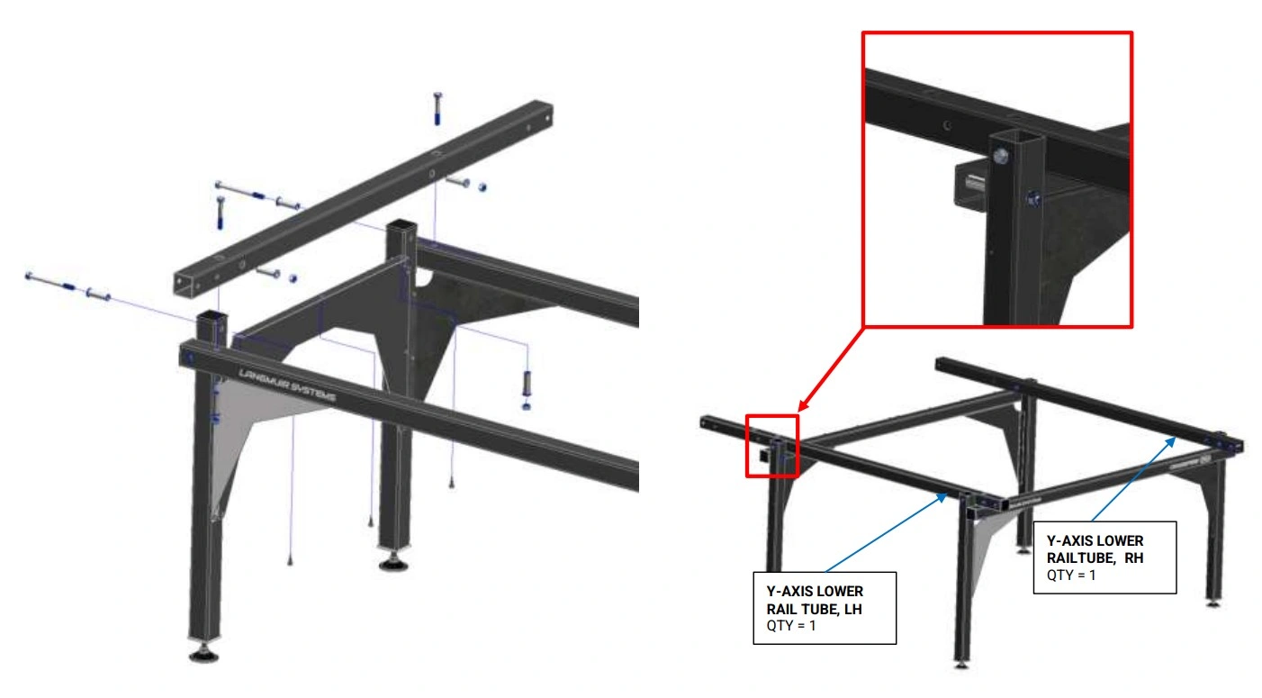
- On a solid surface, place the LH Lower Rail and RH Lower Rail onto each of the Lower Cross Tubes. Secure them using the hardware shown. Hand tighten only.
- Attach each of the leg assemblies using the hardware shown. Hand tighten only.
- Pick up the frame assembly and place it on the ground so that it is supported by the legs.
Materials
Parts
- Hand Tightened Frame Assembly
Hardware
- None
Tools
- Tape Measure
- 9/16" Wrench
- Ratchet with 9/16" Socket
- Soft Faced Hammer or Mallet
- Protractor, Carpenters square, or machinist square
Instructions
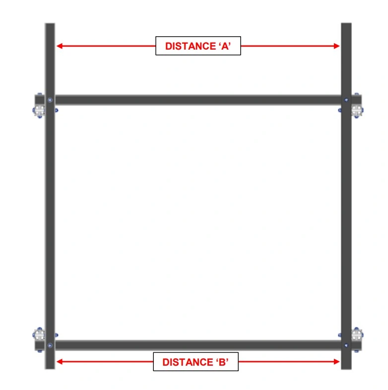
- Using a protractor, carpenter’s square, or combination square, make the Lower Rail Tubes perpendicular to the Lower Cross Tubes.
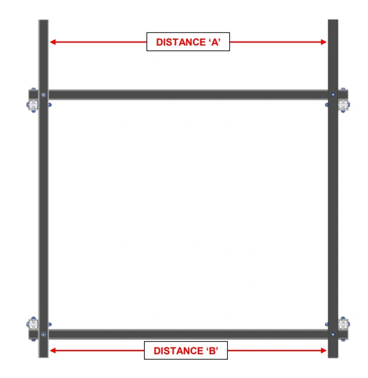
- Using a tape measure, measure the distance between the LH and RH Lower Rails at each end (Distance ‘A’ and Distance ‘B’). If the two measurements are different by more than 1/32”, lightly tap on one of the lower rails to equalize the spans.
- Carefully tighten the bolts that connect the LH Lower Rail and RH Lower Rail to the Lower Cross Tubes.
- Double check that the LH and RH Lower Rails are still parallel within 1/32” after tightening. If they are not, repeat steps 1 and 2.
- Seat the bolts that secure the legs to the Frame, but DO NOT tighten them at this step. The goal is to simply take up the slack in the joint. The legs will be wobbly at this step which is OK. The leg bolts will be tightened at a later step.
3: Install Y-Axis Rails and Carriages
First, complete the assembly of the Y-Axis bearing block carriages.
Materials
Parts
- (2) Carriage Weldment (RH and LH)
- (4) Bearing Block Assembly
Hardware
- (16) Bag 7 SOCKET HEAD CAP SCREW, 1/4"-20 X 3/4"
- (16) Bag 19 1/4" WASHER
- (16) Bag 16 SERRATED FLANGE NUT, 1/4"-20
Tools
- 3/16" Hex Key
- 7/16" Wrench
Instructions
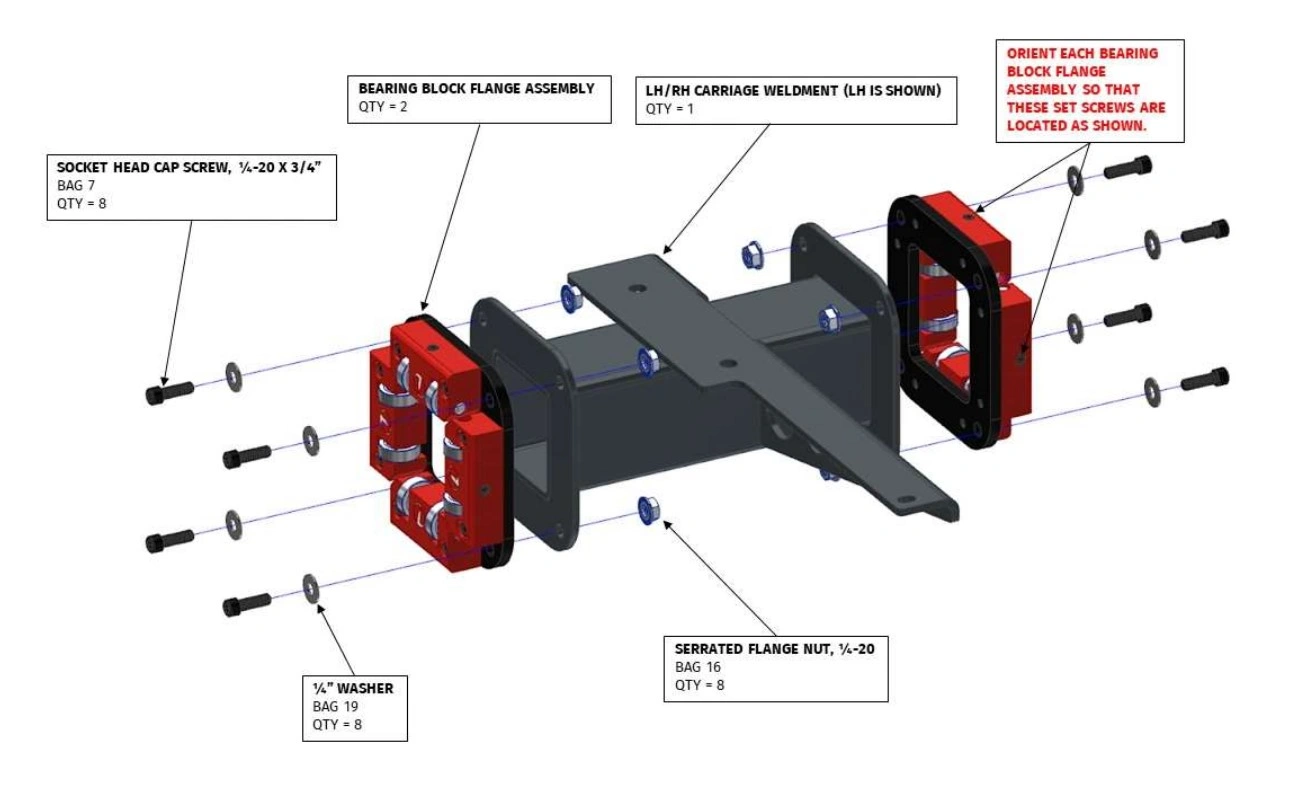
- Secure one Bearing Block Assembly to each flange of the Carriage Weldment. The bearing block assembly must be oriented such that the set screws are in proper location as shown. Do not tighten the screws, they should only be finger tight. Additionally, the adjustable bearing blocks should be free floating and the socket head cap screws should not be tight.
- Repeat assembly instructions for the second carriage.
Materials
Parts
- (2) Carriage Assembly (RH and LH)
- (2) Y-Axis Rail
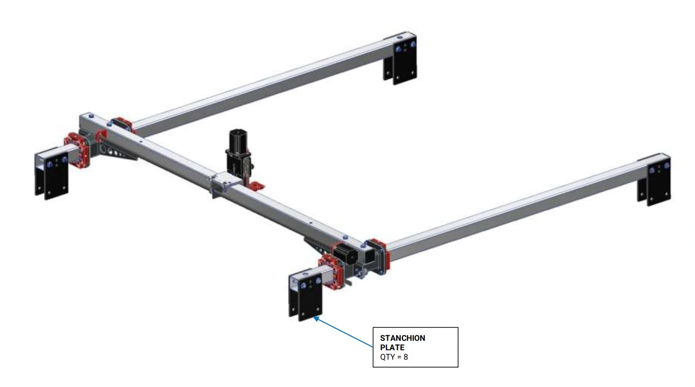
- (8) Stanchion Plate
Hardware
- (16) Bag 3 HEX HEAD CAP SCREW, 3/8-16 X 3
- (32) Bag 20 WASHER, 3/8"
- (16) Bag 13 HEX NUT, 3/8"
Tools
- (2) 9/16” Wrench
Instructions
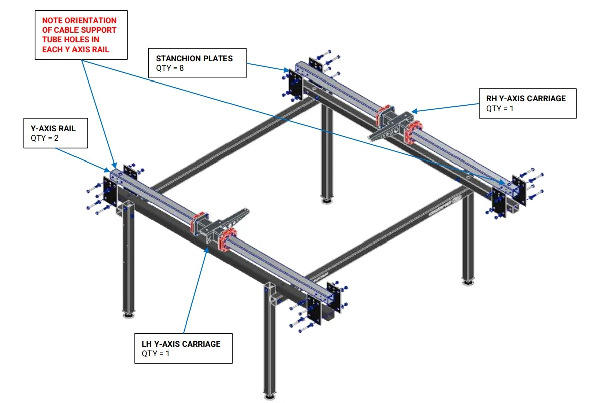
- Insert one Y-Axis Rail into each of the Y-Axis Carriage assemblies. The orientation of each Y-Axis Rail is important and must match what is shown in the diagrams.
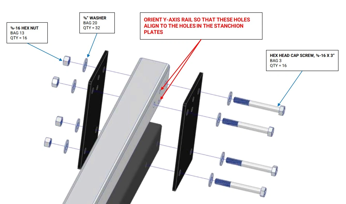
- Secure the Y-Axis Rails to the machine frame assembly using the Stanchion Plates and fasteners shown. Make sure that ¼” diameter holes in the Y-Axis Rail line up to the holes in the Stanchion Plates. If they do not line up, then the Y-Axis Rail is likely installed upside down.
- Tighten each of the bolts that secures the stanchion plates to both lower rail tubes. DO NOT tighten the bolts that secure the stanchion plates to the Y Axis Rails. They will be tightened in a later step.
- Note: The carriage bearings should be loose on the rails. They will be pre-loaded in a later step.
4: Install Gantry & Z-Axis
Complete the Z-Axis assembly and mount it to the X-Axis carriage.
Materials
Parts
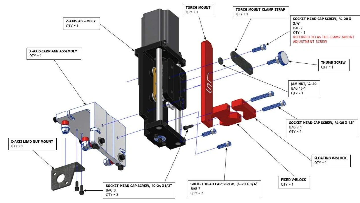
- (1) Z-Axis Assembly
- (1) Torch Mount
- (1) Fixed V-Block
- (1) Floating V-Block
- (1) Torch Mount Clamp Strap
- (1) Thumb Screw
- (1) X-Axis Carriage Assembly
- (1) X-Axis Lead Nut Mount
Hardware
- (3) Bag 8 SOCKET HEAD CAP SCREW, 10-24 X 1/2"
- (3) Bag 7 SOCKET HEAD CAP SCREW, 1/4-20 X 3/4"
- (2) Bag 7-1 SOCKET HEAD CAP SCREW, 1/4-20 X 1½"
- (1) Bag 16-1 JAM NUT, 1/4-20
Tools
- 5/32" Hex Key
- 3/16" Hex Key
- 7/16" Wrench
Instructions
- Secure the Fixed Torch V-Block to the Torch Mount with a Bag 8 Socket Head Cap Screw. Fully tighten.
- Attach the Floating Torch V-Block to the Fixed Torch V-Block with Bag 7-1 Socket Head Cap Screws. Screw the bolts in a few turns each.
- Secure the Z-Axis Assembly to the X-Axis Carriage using Bag 7 Socket Head Cap Screws. The key protrusion on the back of the Z-Axis Assembly should fit snugly in the shallow slot of the X-Axis Carriage. Fully tighten the screws.
- Insert the Bag 7 Socket Head Cap Screw into one of the holes of the Torch Mount Clamp Strap. Screw the Bag 16-1 Jam Nut onto the screw.
- Place the Torch Mount Assembly into the slot of the Z Axis Carriage. Screw the Clamp Strap Adjustment Screw into the left hand threaded hole in the Z-Axis Carriage so that Torch Mount Clamp Strap lays on top of the Torch Mount.
- Insert the Thumb Screw into the other hole of the Torch Mount Clamp Strap and screw it into the Z Axis Carriage.
- Adjust the Clamp Strap Adjustment Screw either in or out until the Torch Mount Clamp Strap lays flat against the Torch Mount with the Thumb Screw hand tightened. Once the Clamp Strap Adjustment Screw is properly adjusted, tighten the Bag 16-1 Jam Nut.
- Attach the X-Axis Lead Nut Mount to the X-Axis Carriage Assembly using Bag 8 Socket Head Cap Screws. These screws should be seated fully, but the mount should be able to float.
Materials
Parts
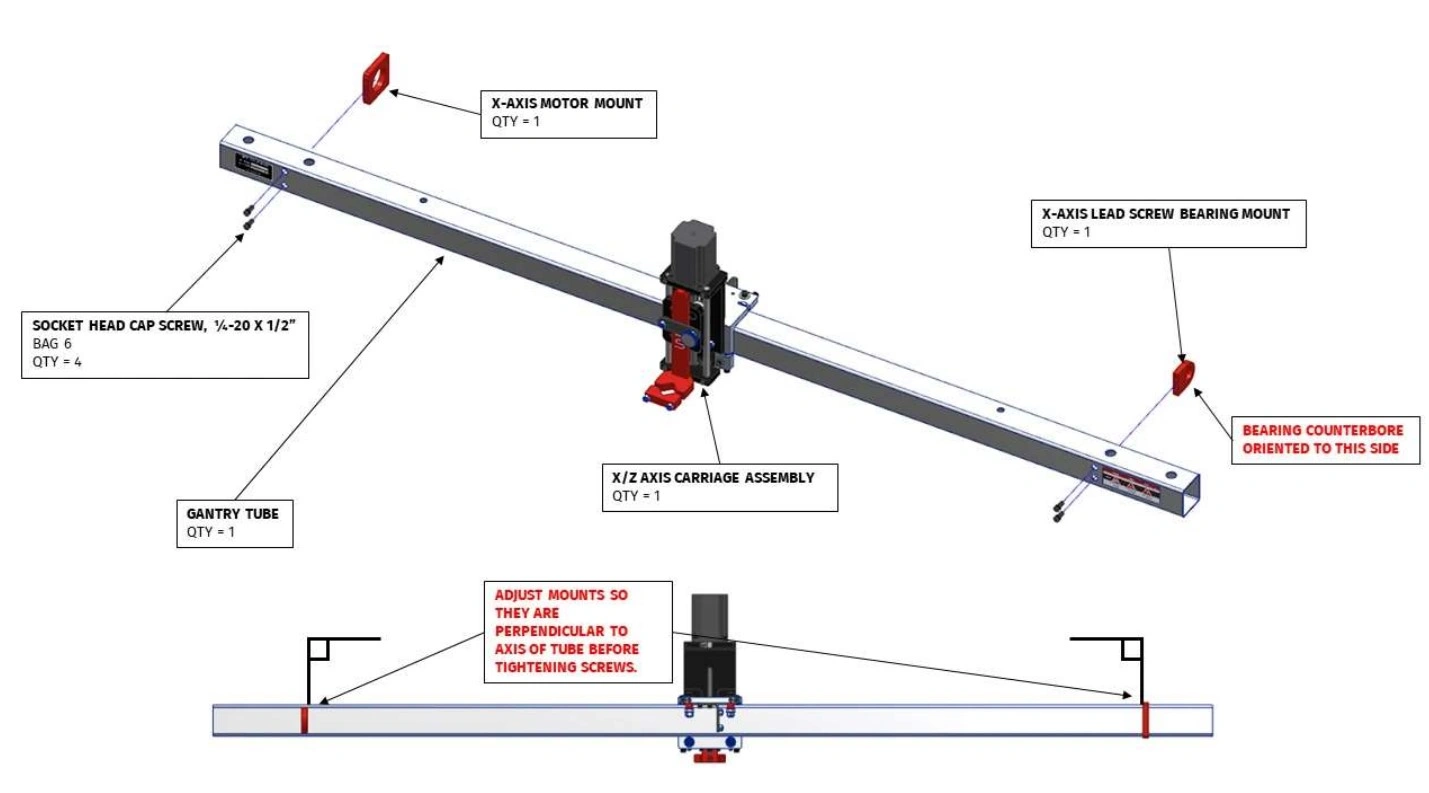
- (1) X/Z-Axis Carriage Assembly
- (1) Gantry Tube
- (1) X-Axis Lead Screw Bearing Mount
- (1) X-Axis Motor Mount
Hardware
- (4) Bag 6 SOCKET HEAD CAP SCREW, 1/4-20 X 1/2"
Tools
- 3/16" Hex Key
- Protractor or Combination Square
Materials
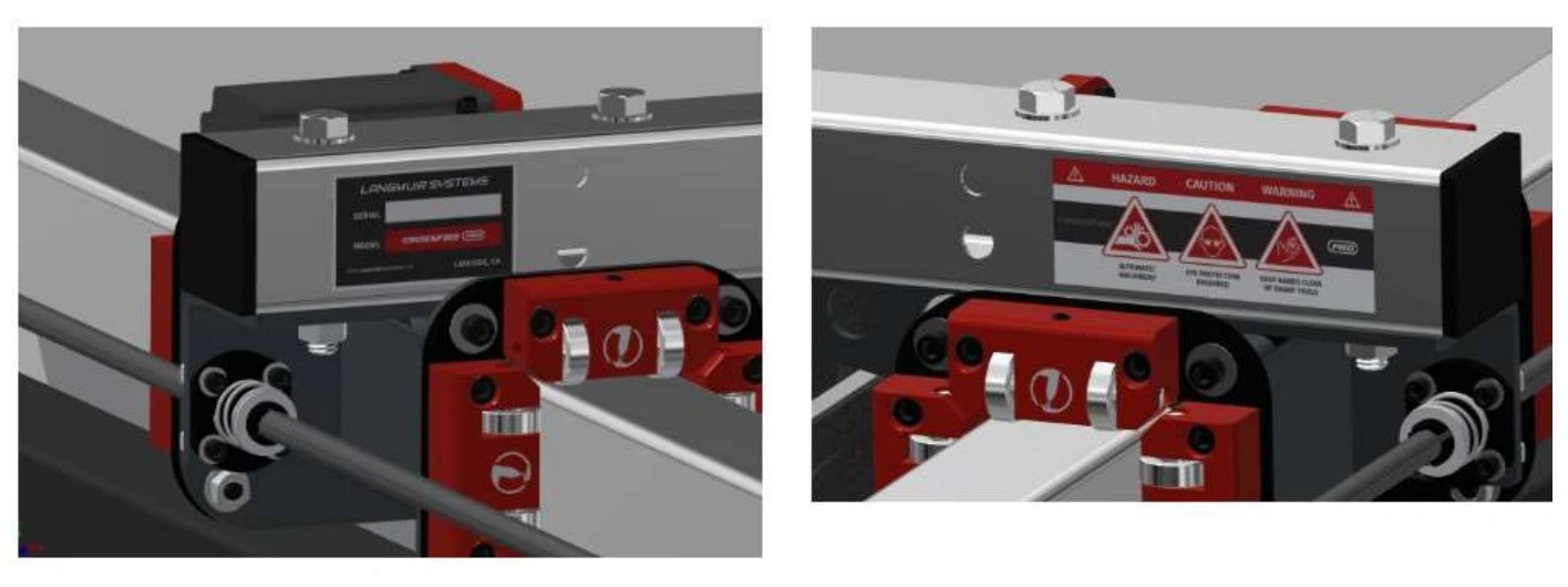
The assembly diagrams show the Gantry Rail Tube with Nameplate and Warning stickers installed. To install, center both stickers on each side of the Gantry Tube between the end of the tube and the 2 hole cutouts as shown in the images below.
Instructions
- Slide the X/Z Axis Carriage Assembly onto the Gantry Tube. The orientation is important and must match the diagram. Note that the bearings should be loose at this point- they will be adjusted in a later step.
- Secure the X Axis Motor Mount to the Gantry Tube using the Bag 6 socket head cap screws. The X Axis Motor Mount is symmetric so the orientation is not important. Before fully tightening the cap screws, use a protractor to square the X Axis Motor Mount to the Gantry Tube. Please note that the X-Axis motor mount is shorter than the Y-Axis motor mounts (2).
- Secure the X Axis Lead Screw Bearing Mount to the Gantry Tube using the remaining Bag 6 screws. Note that the bearing counterbore must be facing to the right when looking at the gantry from the front. Before fully tightening the cap screws, use a protractor to square the X Axis Lead Screw Bearing Mount to the Gantry Tube. Please note that the X-Axis lead screw bearing mount is shorter than the Y-Axis lead screw bearing mounts (2).
Materials
Parts
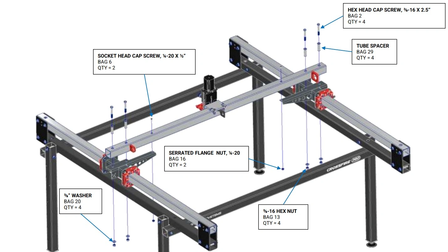
- (1) Gantry Assembly
- (2) Y-Axis Carriages (on assembled machine)
Hardware
- (4) Bag 2 HEX HEAD CAP SCREW, 3/8-16 X 2.75"
- (4) Bag 13 3/8-16 HEX NUT
- (4) Bag 20 3/8" WASHER
- (2) Bag 6 SOCKET HEAD CAP SCREW, 1/4-20 X ½"
- (2) Bag 16 SERRATED FLANGE NUT, 1/4-20
- (4) Bag 29 Tube Spacer
Tools
- (2) 9/16" Wrench
- 3/16" Hex Key
- 7/16" Wrench
Instructions
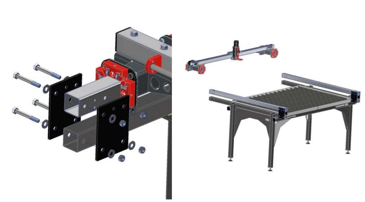
- Attach the Gantry Assembly to the Y-Axis Carriages using the fasteners shown. DO NOT tighten these bolts. Note: The bag 6 socket head cap screws must be passed through the clearance hole in the top of the gantry tube. Consider taping the screw to the hex key to prevent it from dropping into the tube.
5: Y-Axis Adjustment
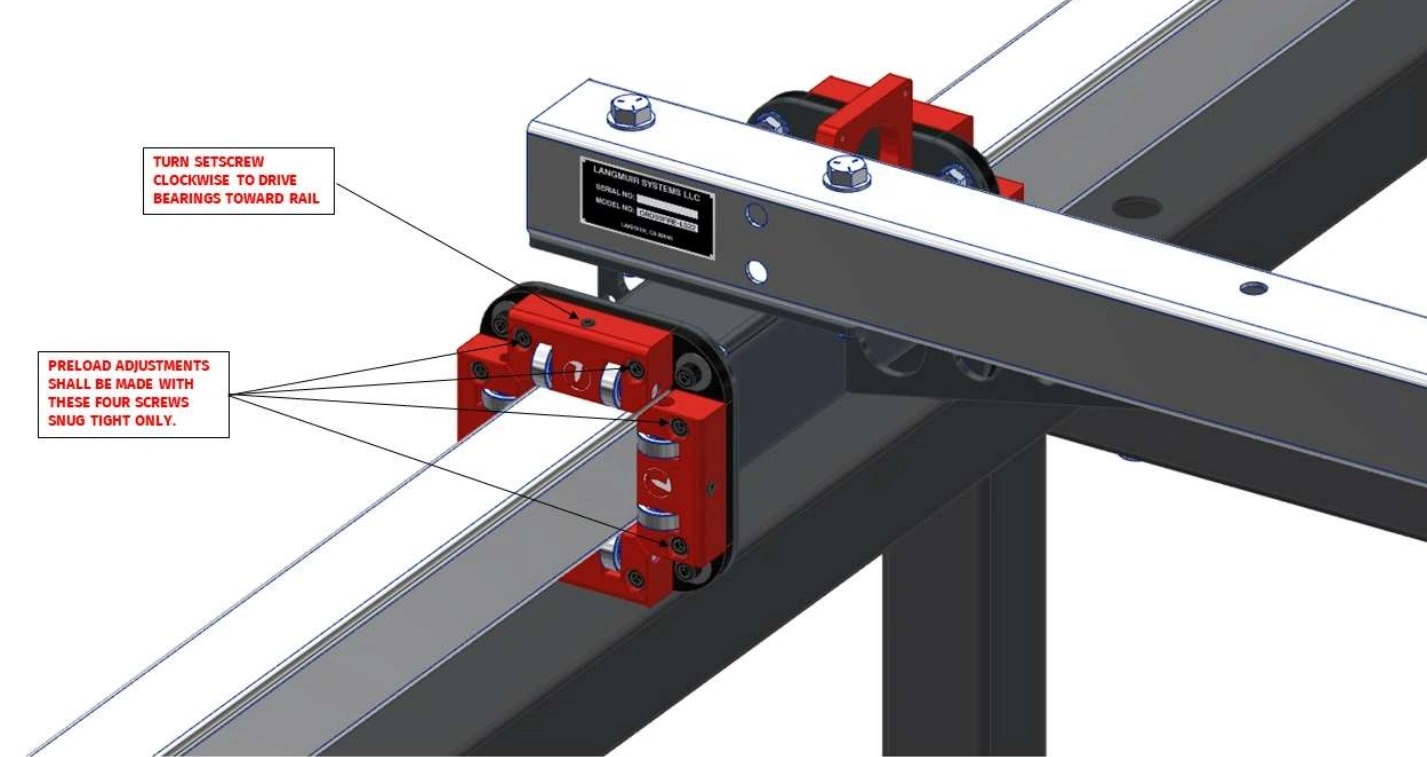
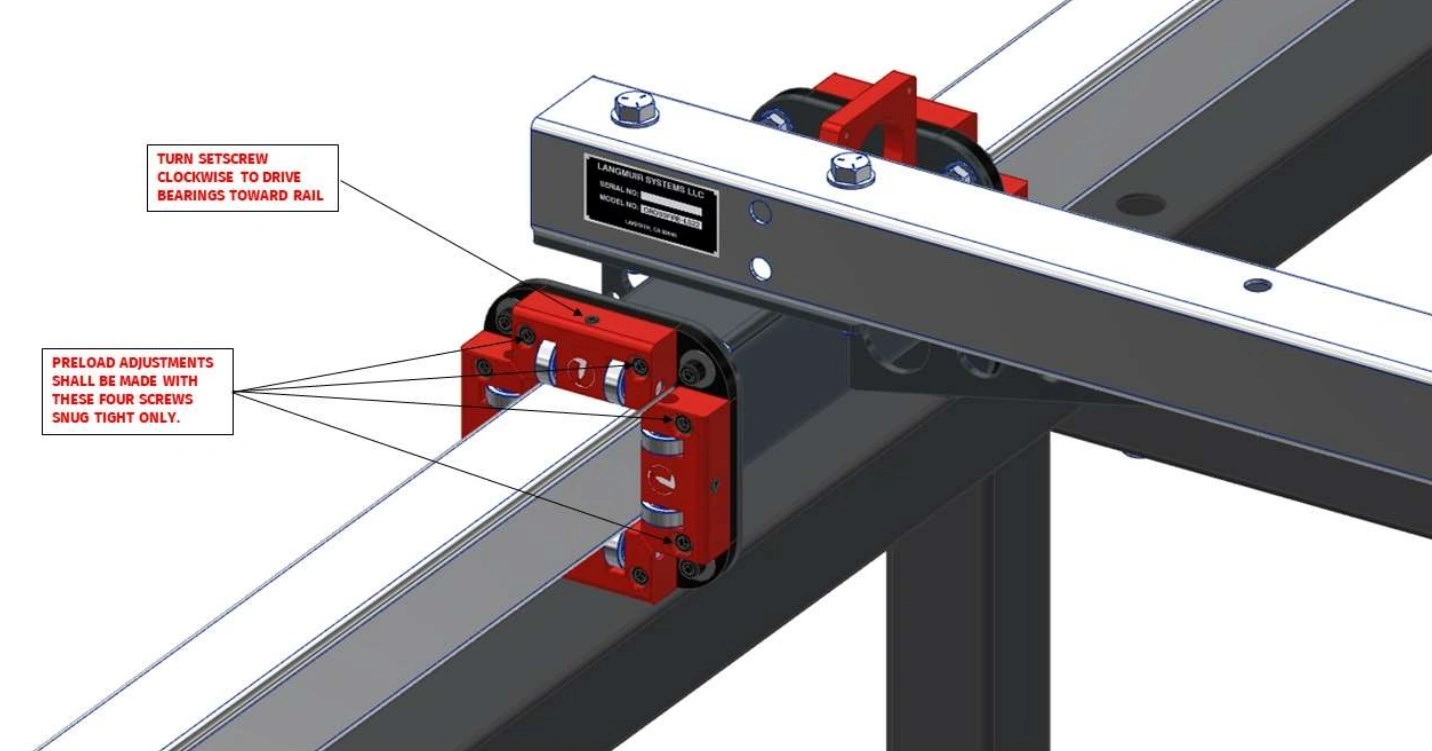
Each Y-Axis Carriage Assembly includes two Bearing Block Assemblies. Each Bearing Block Assembly contains four bearing blocks; two are fixed and two are adjustable. The goal of this section is to adjust the Adjustable Bearing Block to ensure that the bearings are properly preloaded into the Y-Axis Rails.
Materials
Parts
- (8) Assembled Machine Adjustable Bearing Blocks
Hardware
- None (pre-installed)
Tools
- 3/16" Hex Key
- 1/8" Hex Key
Instructions
- Each Y-Axis Carriage Assembly includes two Bearing Block Assemblies. Each Bearing Block Assembly contains four bearing blocks; two are fixed and two are adjustable. The goal of this assembly section is to adjust the Adjustable Bearing Block to ensure that the bearings are properly preloaded into the Y-Axis Rails.
- On each Adjustable Bearing Block, seat both socket head cap screws and then back them off approximately 1/4 turn. Next, slowly turn the adjustment set screw clockwise. Stop turning the set screw when at least one of the two opposing Fixed Bearing Block Bearings is in contact with the rail and when no play can be felt.
- Once Step 2 is complete, tighten the socket head cap screws that secure the Adjustable Bearing Block to the backing plate.
- Complete Steps 2 and 3 for each of the eight Adjustable Bearing Blocks that the machine has.
Materials
Parts
- (1) Assembled Machine Gantry
Hardware
- None
Tools
- (2) 9/16" Wrench
- 3/16" Hex Key
- 7/16" Wrench
Instructions
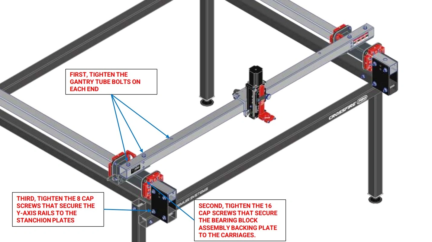
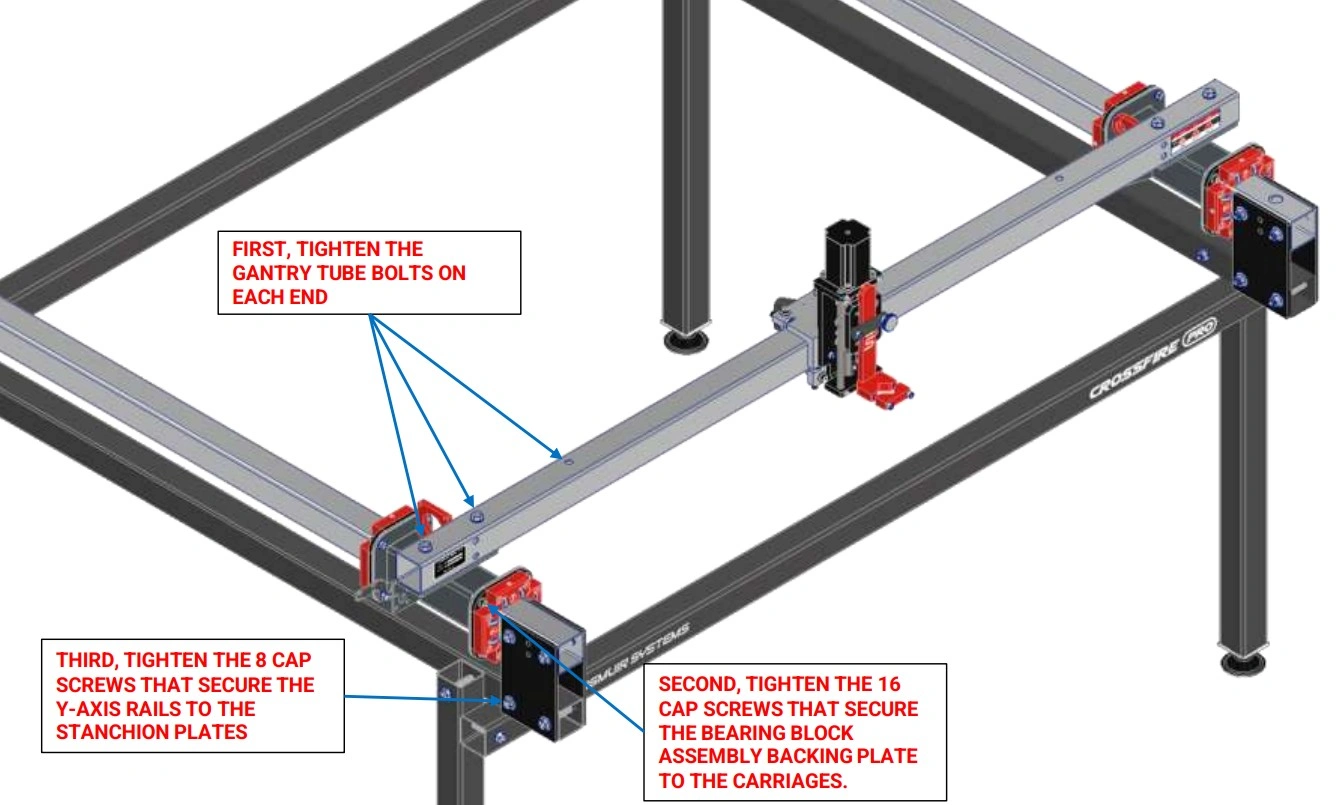
- Slide the Gantry Assembly along the Y-Axis Rails until the bearings touch the Stanchion Plates as shown.
- Tighten the 6 fasteners that secure the Gantry Tube to the Y-Axis Carriages.
- Tighten the 16 cap screws that secure the Bearing Block Assemblies to the Y-Axis Carriages.
- Tighten the 8 bolts that secure the Y Axis Rails to the Stanchion Plates that were left loose in a previous step.
- Cycle the Gantry Assembly back and forth along the Y-Axis Rails to make sure that it moves freely. If it does not, repeat previous steps to make the Y-Axis Rails parallel.
- Verify there is no lash/play between the rolling carriages and the rails. If there is, repeat Step 3 of the previous instruction set to further pre-load the adjustable.
6: Join & Install Water Table
Join both halves of the water table.
Materials
Parts
- (2) Water Table Half Section
Hardware
- Silicone Sealant
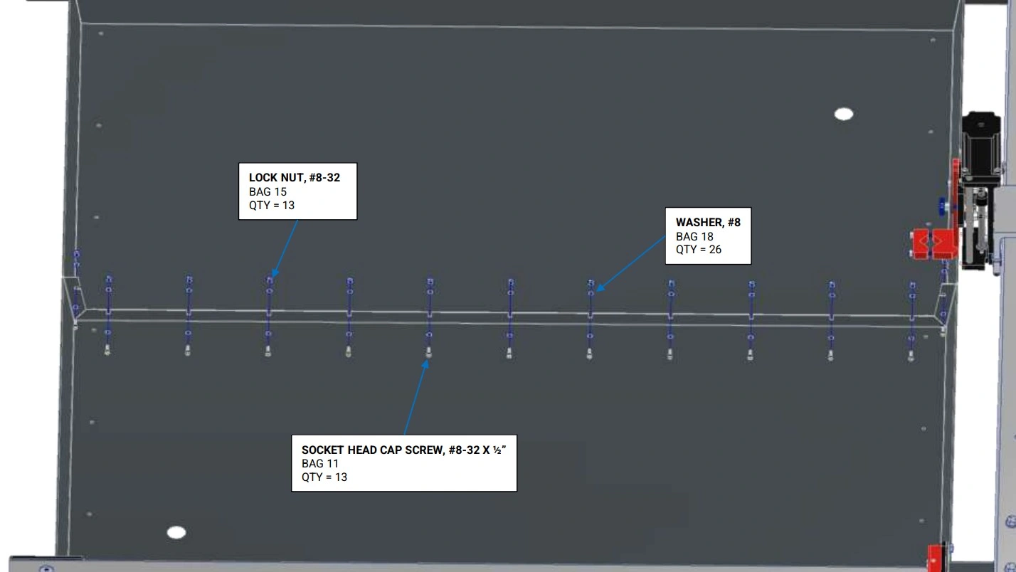
- (10) Bag 11 SOCKET HEAD CAP SCREW, 8-32 X 1/2"
- (20) Bag 18 WASHER, #8
- (10) Bag 15 LOCK NUT, #8-32
Tools
- 9/64" Hex Key
- 11/32" Wrench
Instructions
- Thoroughly clean the flange face of each Water Table Half Section. Before proceeding, make sure that you plan to join the water tables within 5 minutes after applying the silicone adhesive.
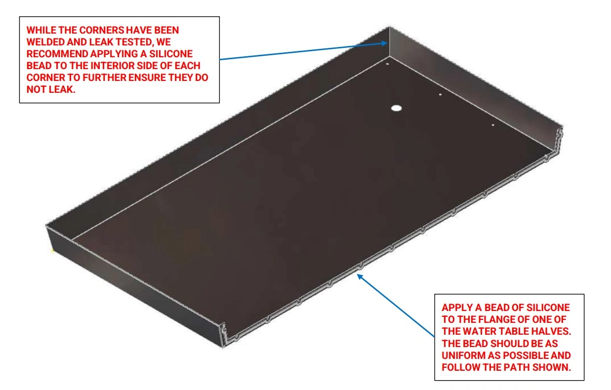
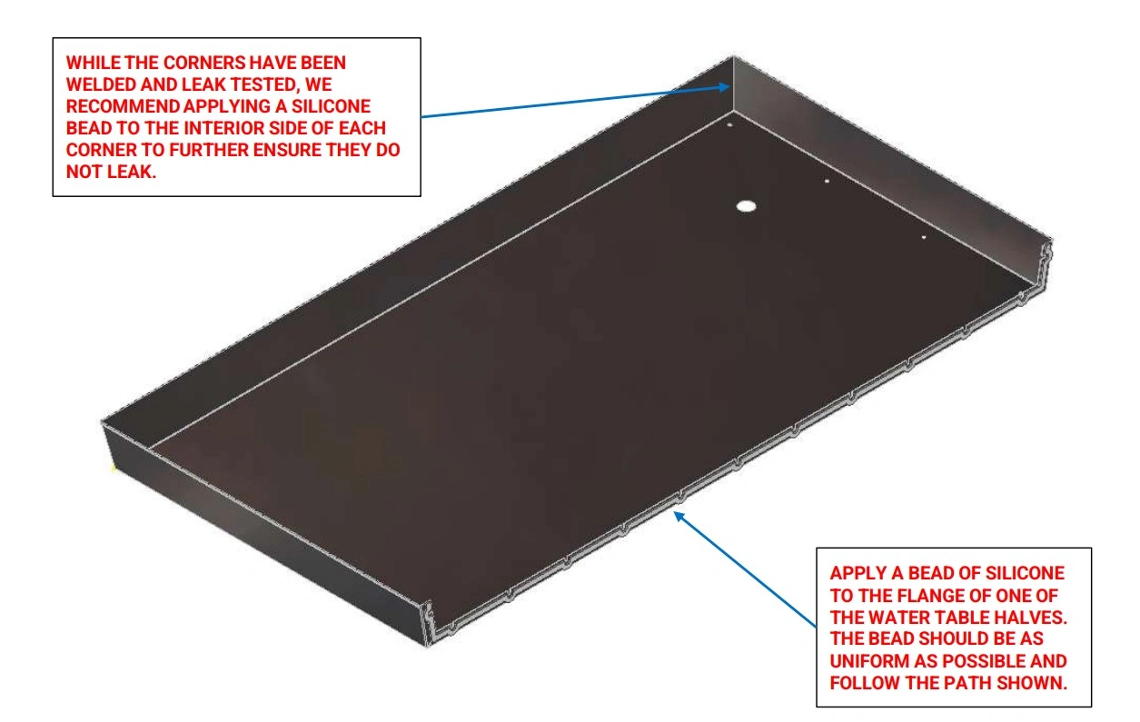
- On one of the Water Table Half Sections, apply a uniform bead of Silicone Sealant (provided) approximately ¼” in diameter along the path shown.
- Apply a bead of silicone to the inside of each of the four welded corners
Instructions
- Place both Water Table Half Sections onto the machine frame with a gap between the two.
- Carefully squeeze the flanges together and install all fasteners as shown. Tighten the fasteners to a medium level of tightness. It is extremely important that the bottom of the water tables are even with each other before fully tightening the screws. Wipe away any squeezed out Silicone Sealant. Allow to cure for 24 hours before filling with water.
Materials
Parts
- (2) Brass Drain Plug
- (1) Water Table (joined)
- (1) Machine Frame
Hardware
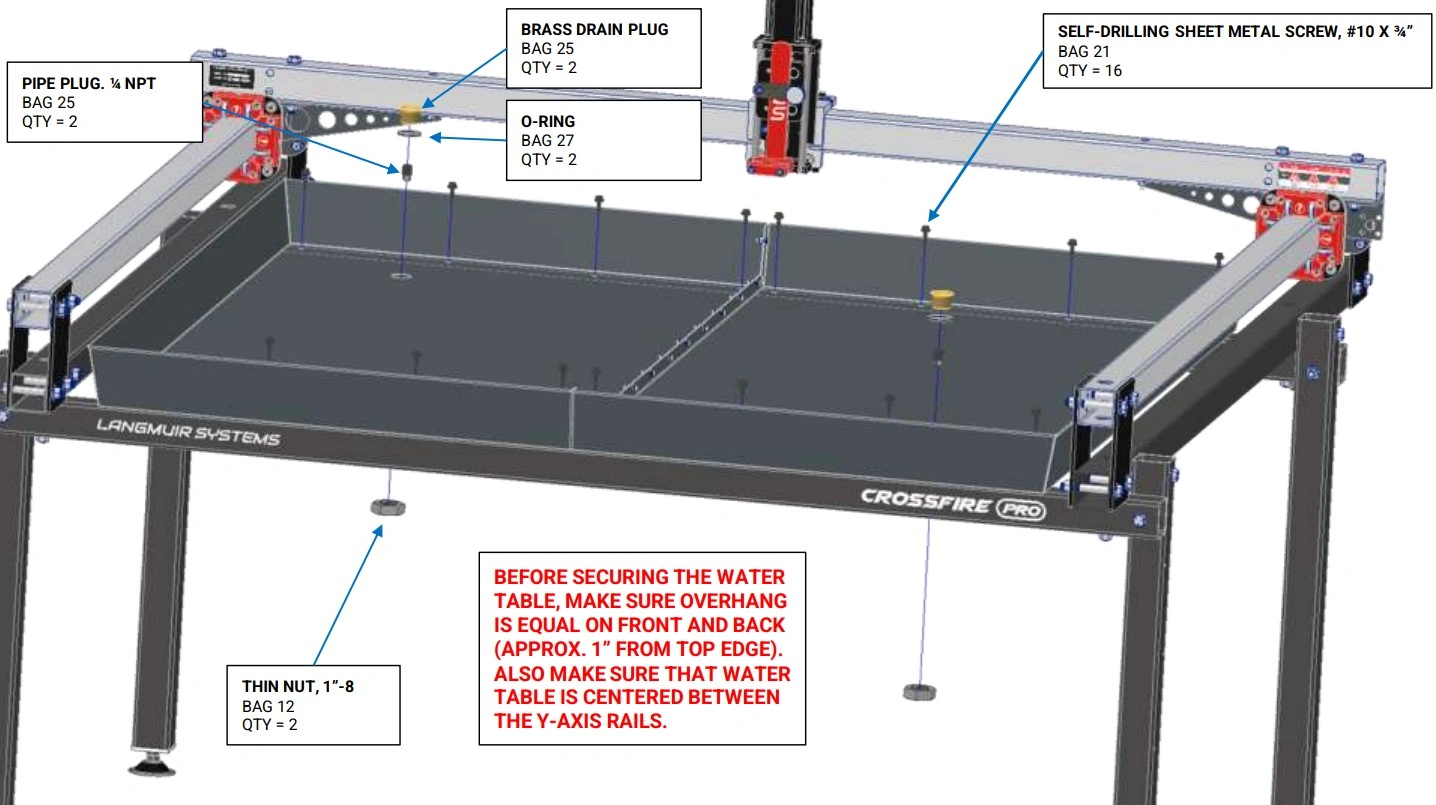
- (16) Bag 21 SELF-DRILLING, SEALING SHEET METAL SCREW, #10 x 3/4”
- (2) Bag 12 THIN NUT, 1”-8
- (2) Bag 27 O-RING
- (2) Bag 25 PIPE PLUG, ¼” NPT
Tools
- Drill with 5/16” socket
- Tape Measure
- 5/16” Wrench

Instructions
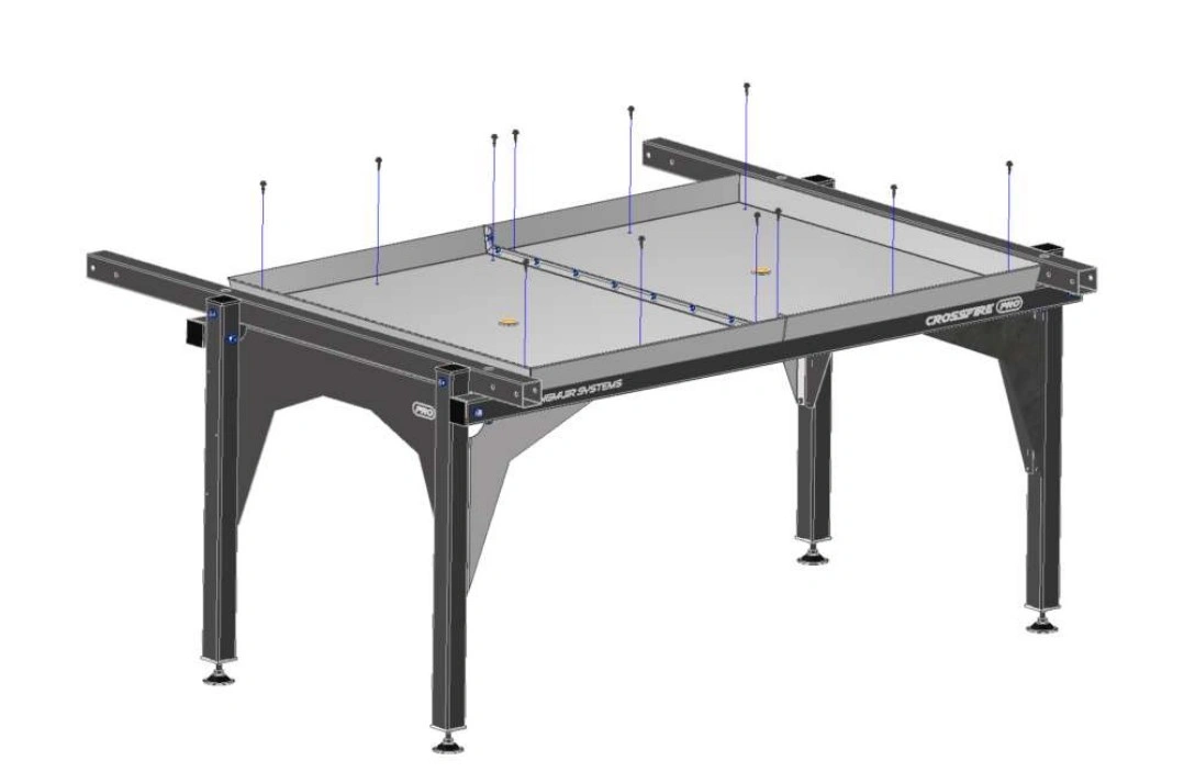
- Use a tape measure to center the Water Table in both directions on the machine frame. It is critical that the amount that the Water Table overhangs the Lower Cross Tubes is equal on the front and the back.
- With the Water Table properly positioned, shoot the Bag 21 Self-Drilling Sealing Sheet Metal Screws through the holes in the Water Table into the Lower Cross Tubes using a drill gun. Clear any chips out to ensure a water tight seal.
- For each Drain Plug Assembly (2), slide the Bag 27 O-Ring onto the outer diameter of the Brass Drain Plug. Insert the Brass Drain Plug into the hole in the Water Table. Reach underneath the Water Table and screw the Bag 12 Thin Nut onto the Brass Drain Plug and hand tighten. Screw the Bag 25 Pipe Plug into the Brass Drain Plug.
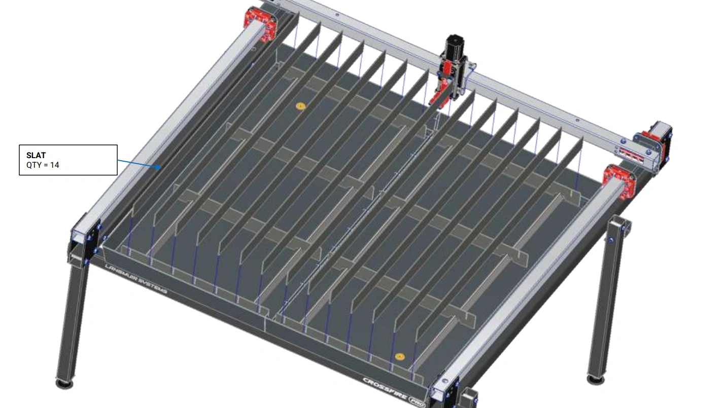
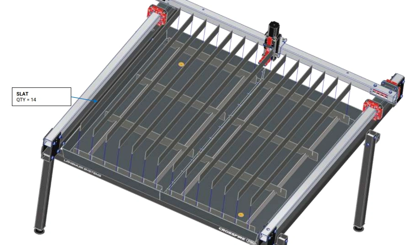
7: Install Slats
Install the slats and slat holders on your CrossFire ProMAX.
Materials
Parts
- (14) Slats
- (8) Slat Holders
- (4) Water Table Slat TP
- (1) Water Table
Hardware
- None
Tools
- Mallet
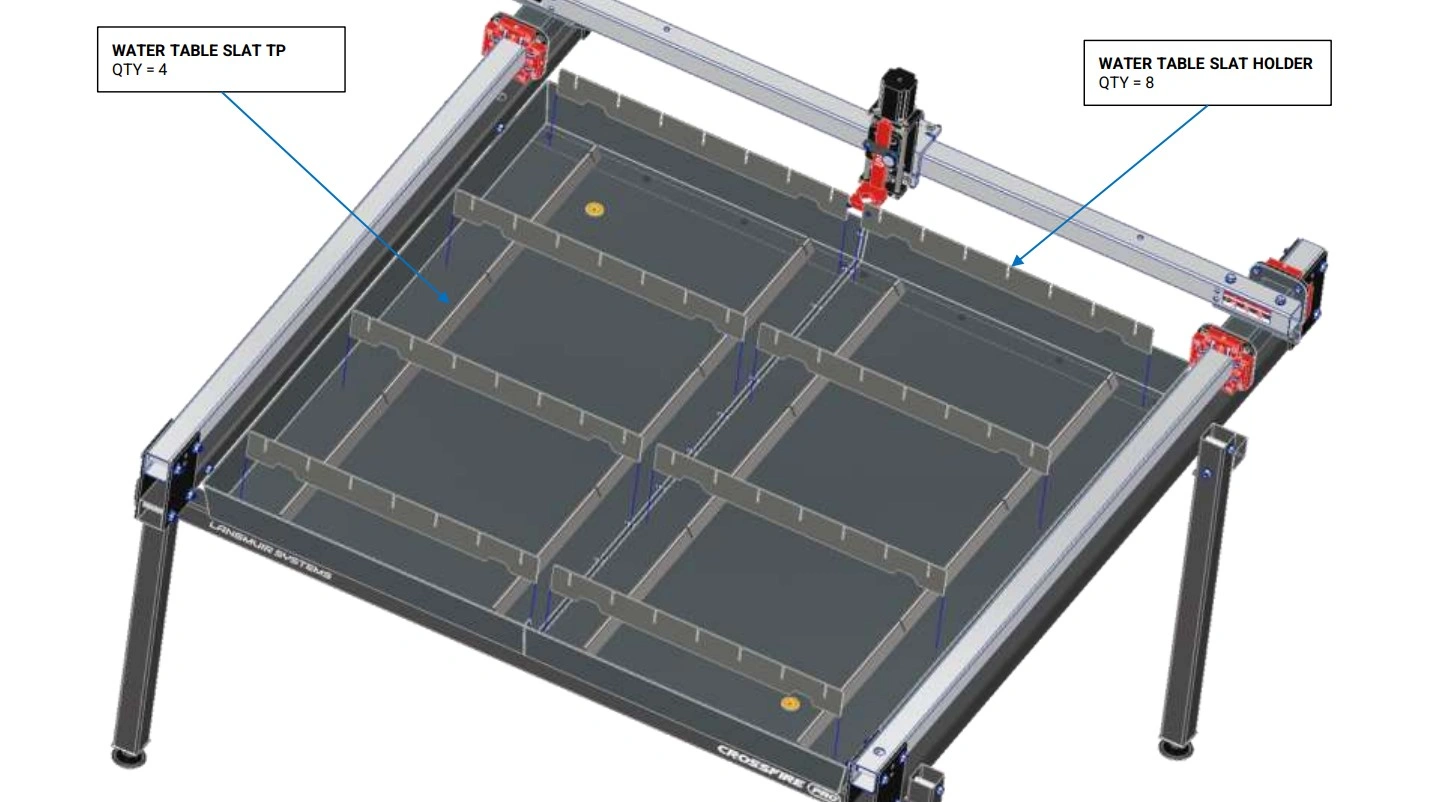
Instructions
- Place the four Water Table Slat TPs at the bottom of the Water Table such that they cover up the previously installed sheet metal screws.
- Insert the Slats into the slots of the Slat Holders. Tap them in with a mallet as needed to fully seat them.
8: Z-Axis Tramming
In this video we demonstrate how to manually tram the Z-axis torch slide so that it is perpendicular to the slat bed when cutting.
Materials
Parts
- (1) Assembled Machine
Hardware
- None
Tools
- 1/8" Hex Key
- Protractor or Combination Square
Instructions
- Follow instructions in video.
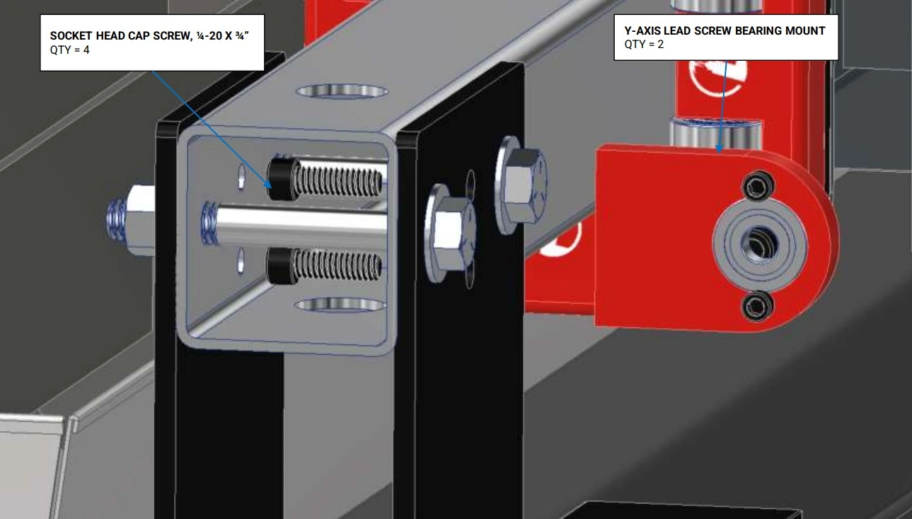
9: Install Lead Screw Bearing Mounts
Install the Y-Axis lead screw bearing mounts.
Materials
Parts
- (2) Y-Axis Lead Screw Bearing Mount
Hardware
- (4) Bag 11 SOCKET HEAD CAP SCREW, 8-32 X 1/2"
- (4) Bag 7 SOCKET HEAD CAP SCREW, 1/4-20 X 3/4"
- (2) Bag 28 608 BALL BEARING
Tools
- 9/64" Hex Key
- 3/16" Hex Key
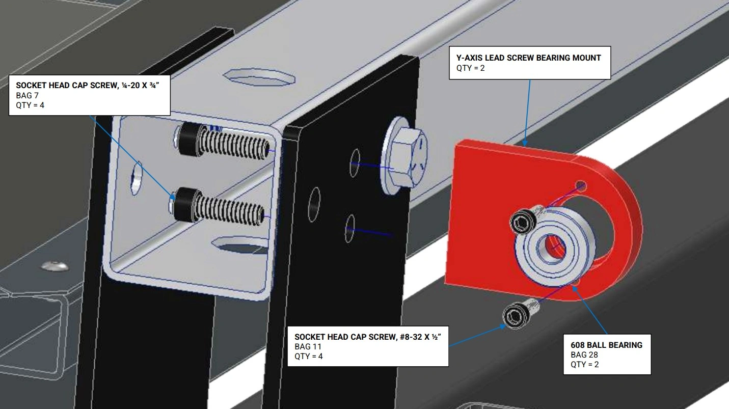
Instructions
- Insert the Bag 28 Ball Bearing into the counterbore of the Y-Axis Lead Screw Bearing Mount. Install the two Bag 11 Socket Head Cap Screws to retain the bearing in the counterbore and tighten fully. Note: a C-clamp may needed to insert the bearing into the bearing mount if a press fit condition exists.
- Secure the Y-Axis Lead Screw Bearing Mount to the left hand Y-Axis Rail using the two Bag 7 Socket Head Cap Screws and hand tighten only. NOTE: the screws have to be inserted through the mounting holes inside of the Y-Axis Rail Tube. Temporarily removing the ⅜” Stanchion Plate bolt makes it easier to install the screws. Replace the ⅜” stanchion plate bolt when complete.
- Repeat Steps 1 and 2 for the other side.
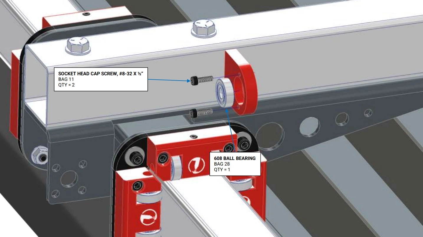
Materials
Parts
- (1) X-Axis Lead Screw Bearing Mount (previously installed)
Hardware
- (2) Bag 11 SOCKET HEAD CAP SCREW, 8-32 X 1/2"
- (1) Bag 28 608 BALL BEARING
Tools
- 9/64" Hex Key
Instructions
- Insert the Bag 28 Ball Bearing into the counterbore of the X-Axis Lead Screw Bearing Mount. Install the two Bag 11 Socket Head Cap Screws to retain the bearing in the counterbore and tighten fully. Note: a C-clamp may needed to insert the bearing into the bearing mount if a press fit condition exists.
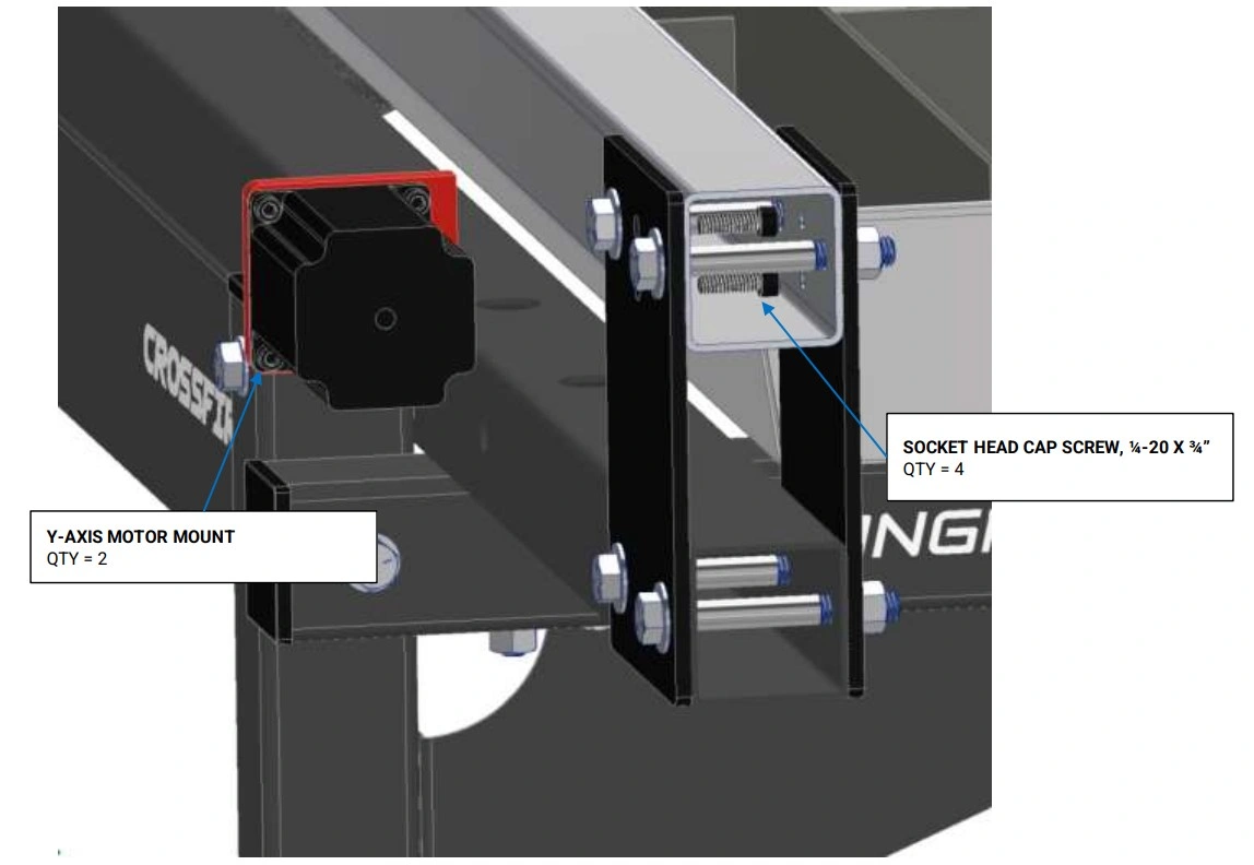
10: Install Motor Mounts & Lead Nuts
Install the mounts for the Y-Axis Stepper motors.
Materials
Parts
- (2) Y-Axis Motor Mount
Hardware
- (4) Bag 7 SOCKET HEAD CAP SCREW, 1/4-20 X ¾"
Tools
- 3/16" Hex Key
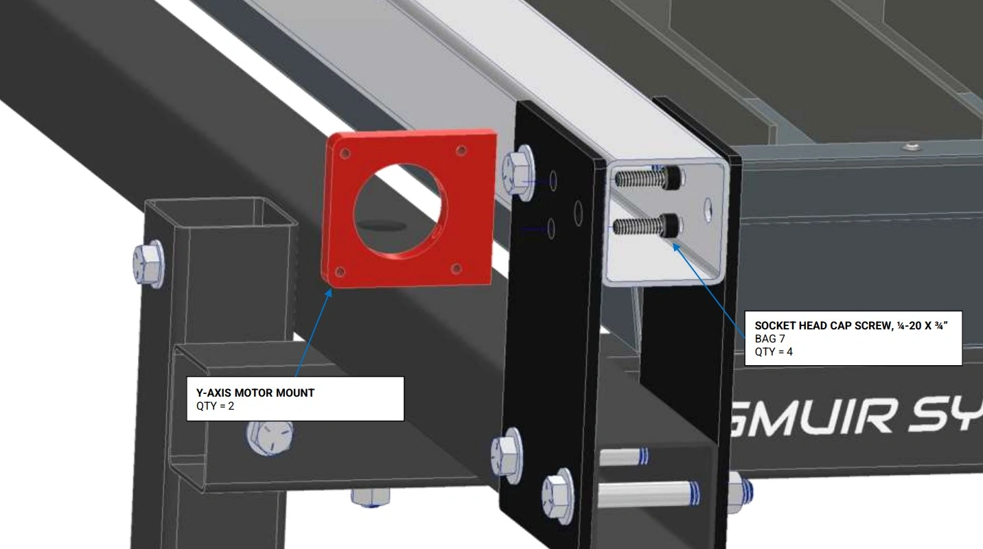
Instructions
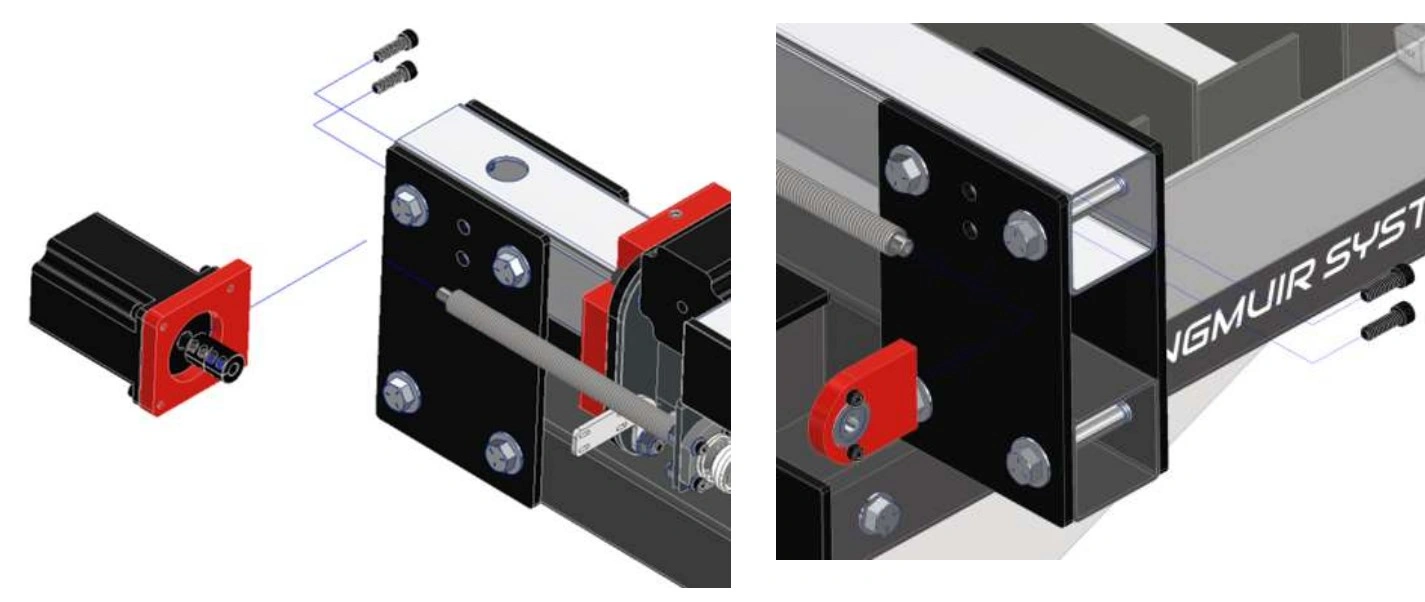
- Secure the Y-Axis Motor Mount to the left hand Y-Axis Rail using the Bag 7 Socket Head Cap Screws and hand tighten only. NOTE: the screws have to be inserted through the mounting holes inside of the Y-Axis Rail Tube. Temporarily removing the ⅜” Stanchion Plate bolts makes it easier to install the screws. Replace the ⅜” Stanchion Plate bolt when complete.
- Repeat Step 1 for the other side.
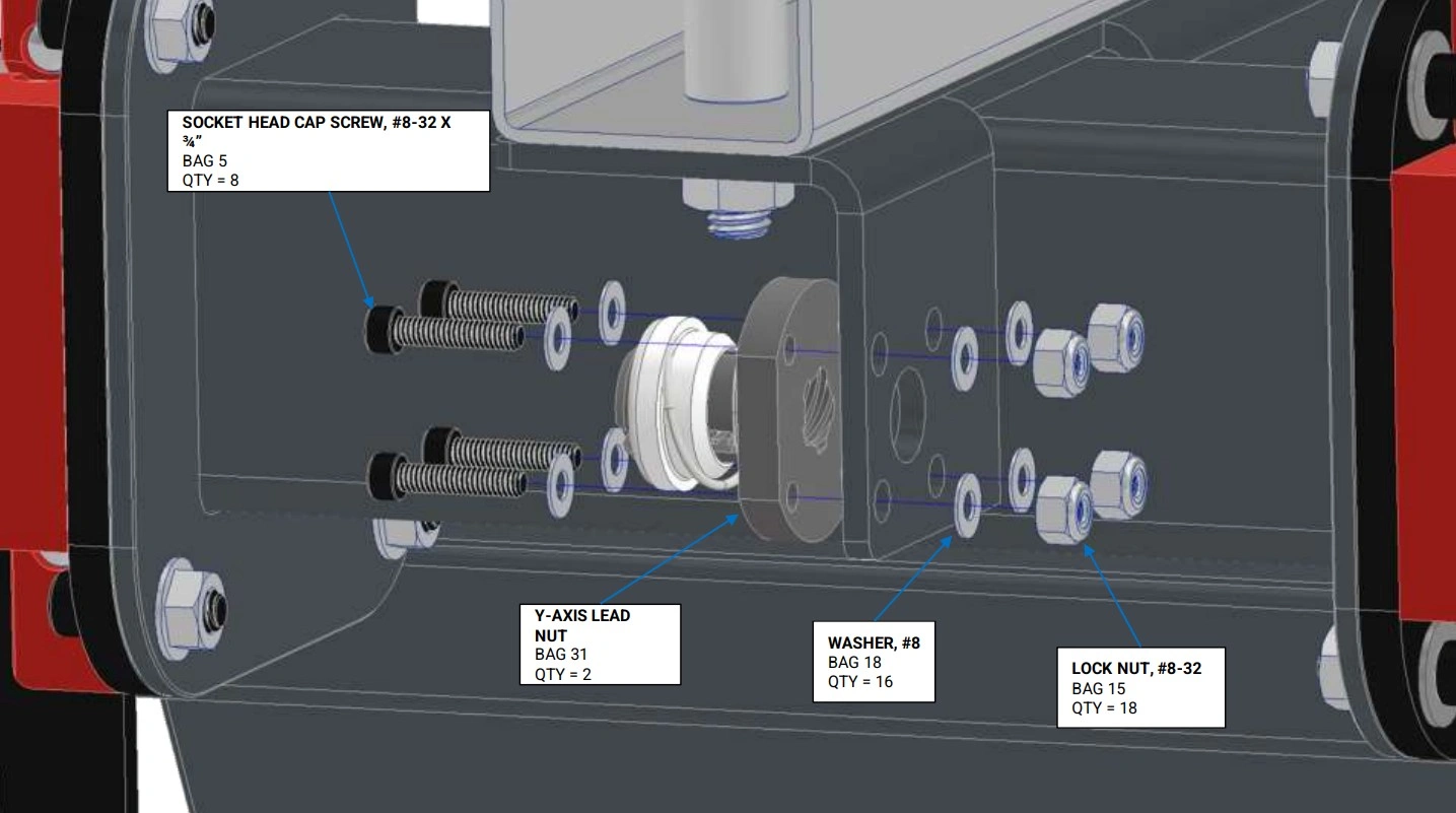
Materials
Parts
- (2) Y-Axis Carriage (on assembled machine)
Hardware
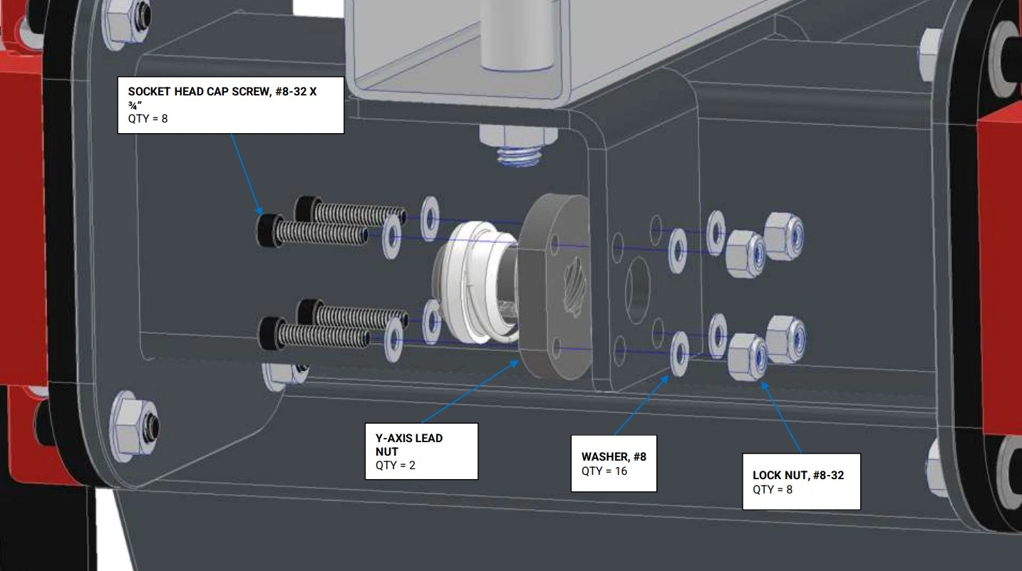
- (8) Bag 5 SOCKET HEAD CAP SCREW, #8-32 X 3/4"
- (16) Bag 18 #8 WASHER
- (8) Bag 15 LOCK NUT, #8-32
- (2) Bag 31 Y-AXIS LEAD NUT
Tools
- 9/64" Hex Key
- 11/32" Wrench
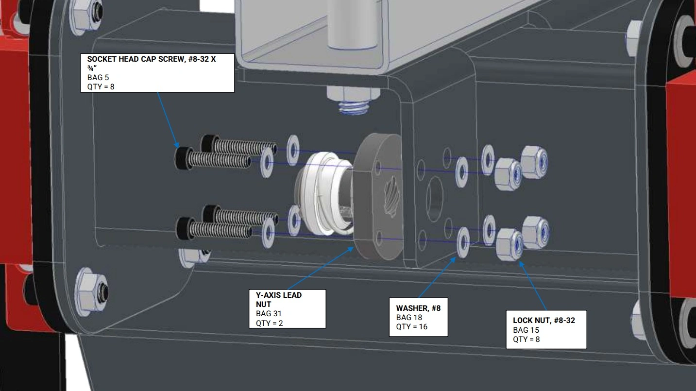
Instructions
- Secure the Bag 31 Y-Axis Lead Nut to the lefthand Y-Axis Carriage using the fasteners shown. Do not fully tighten the screws; the Y-Axis Lead Nut must be able to float in all directions for alignment in a later step.
- Repeat Step 1 for the other side.
Materials
Parts
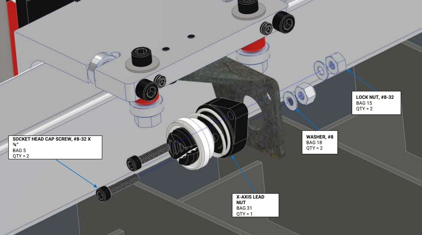
- (1) X Axis Lead Nut Mount Tab (on assembled machine)
Hardware
- (2) Bag 5 SOCKET HEAD CAP SCREW, #8-32 X 3/4"
- (2) Bag 18 #8 WASHER
- (2) Bag 15 LOCK NUT, #8-32
- (1) Bag 31 X-AXIS LEAD NUT
Tools
- 9/64" Hex Key
- 11/32" Wrench
Instructions
- Secure the Bag 31 X Axis Lead Nut to the X-Axis Lead Nut Mount Tab using the fasteners shown. Do not fully tighten the screws; the X-Axis Lead Nut must be able to float in all directions for alignment in a later step.
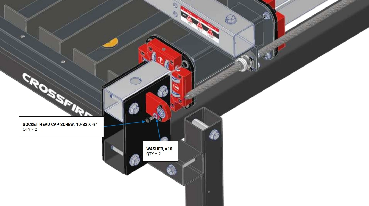
11: Install Lead Screws
Install both of the Y-Axis Lead screws.
Materials
Parts
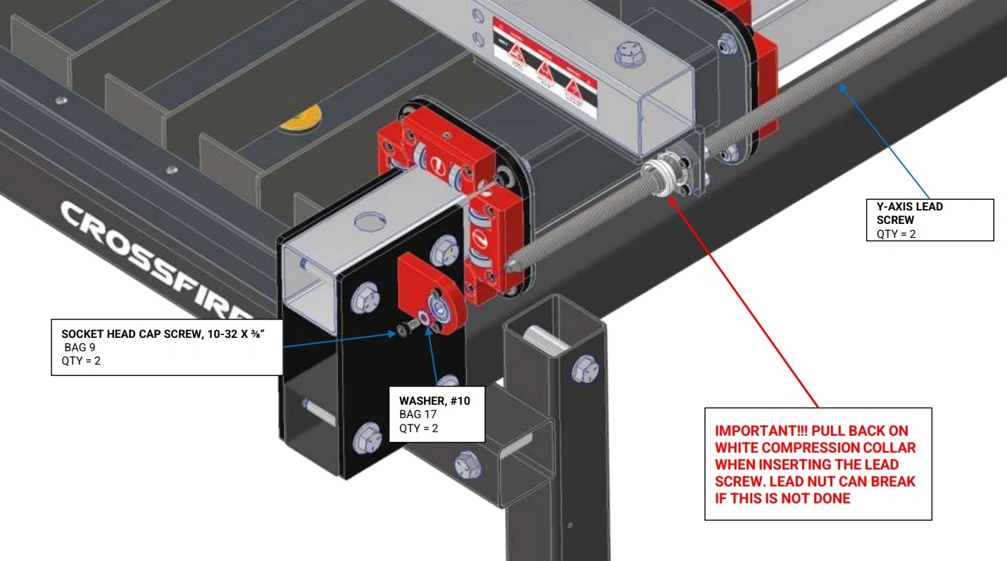
- (2) Y-Axis Lead Screw (1/2")
- (2) Y-Axis Lead Nut (previously installed)
Hardware
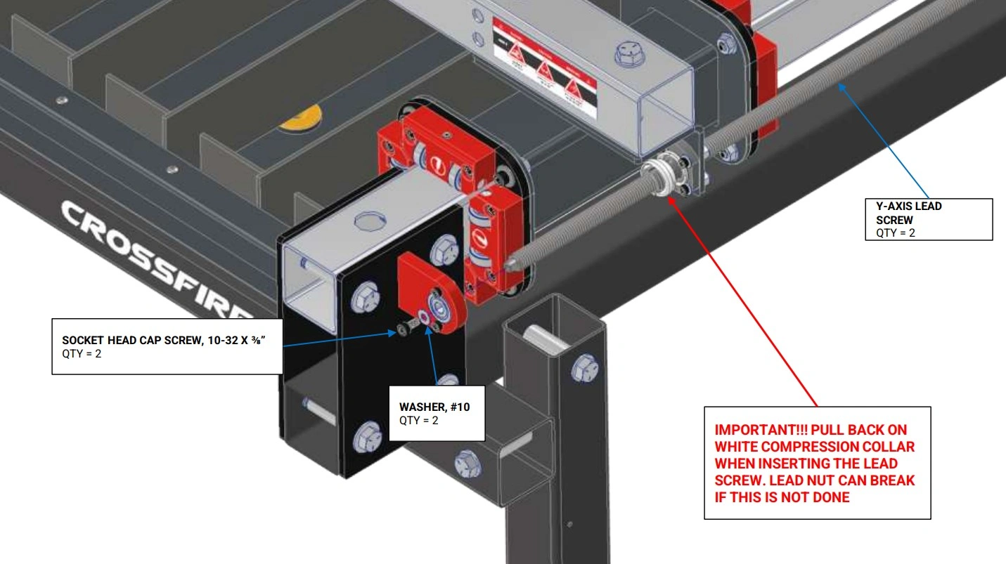
- (2) Bag 9 SOCKET HEAD CAP SCREW, 10-32 X 3/8"
- (2) Bag 17 #10 WASHER
Tools
- 5/32" Hex Key
Instructions
- Position the Gantry in approximately the center of its travel.
- Starting with the end of the that has the tapped hole, screw the Y-Axis Lead Screw into the Y-Axis Lead Nut (make sure to pull back on the White Compression Collar during initial insertion of the lead screw to prevent damage to the lead nut). Continue turning the Y-Axis Lead Screw until it can fit into the bearing that is mounted in the Y-Axis Lead Screw Bearing Mount.
- Secure the lead screw to the bearing using the hardware shown and fully tighten.
Materials
Parts
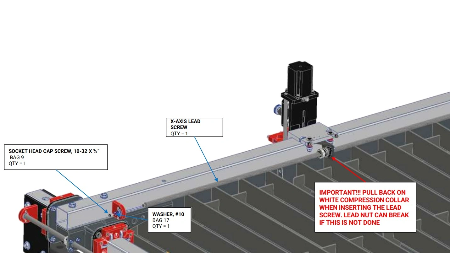
- (1) X-Axis Lead Screw (1/2")
- (1) X-Axis Lead Nut (previously installed)
Hardware
- (1) Bag 9 SOCKET HEAD CAP SCREW, 10-32 X 3/8"
- (1) Bag 17 #10 WASHER
Tools
- 5/32" Hex Key
Instructions
- Position the Gantry in approximately the center of its travel.
- Starting with the end of the that has the tapped hole, screw the X-Axis Lead Screw into the X-Axis Lead Nut (make sure to pull back on the White Compression Collar during initial insertion of the lead screw to prevent damage to the lead nut). Continue turning the X-Axis Lead Screw until it can fit into the bearing that is mounted in the X-Axis Lead Screw Bearing Mount.
- Secure the lead screw to the bearing using the hardware shown and fully tighten.
12: Install Motors
Differentiate between X and Y Stepper Motors
The CrossFire ProMAX utilizes 3 NEMA-23 Stepper motors for smooth accurate motion. The bodies of all 3 motors are identical however, the can be told apart by the lengths of the attached cables. Cable length can either be short (2 motors) or long (1 motor). One of the short cabled and one of the long cabled motors are the Y-Axis Motors while the remaining short cabled motor is the X-Axis Motor.
Materials
Parts
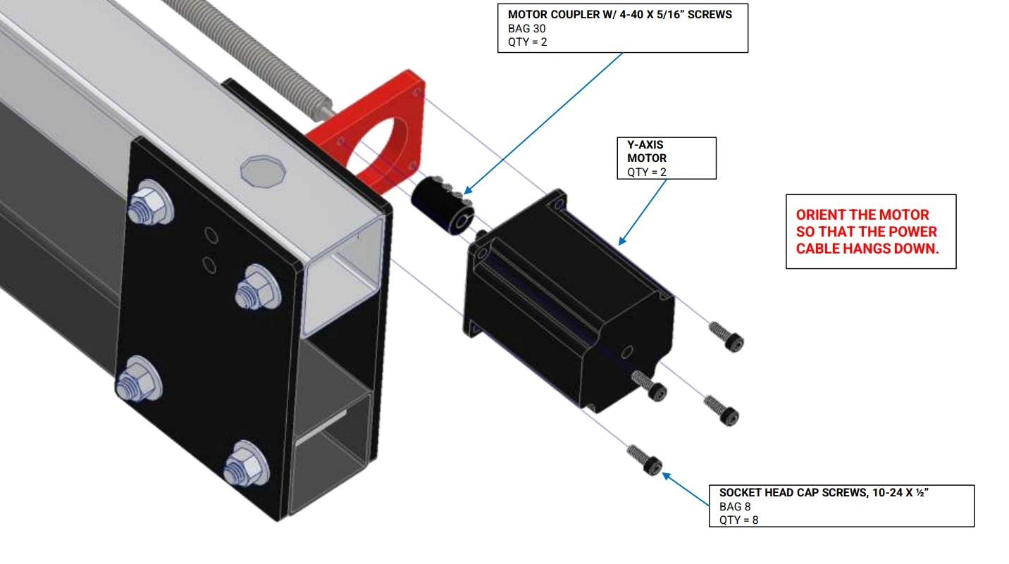
- (1) Y-Axis Motor (short cable)
- (1) Y-Axis Motor (long cable)
Hardware
- (8) Bag 8 SOCKET HEAD CAP SCREW, 10-24 X 1/2"
- (2) Bag 30 MOTOR COUPLER
Tools
- 5/32" Hex Key
- 3/32" Hex Key
- 3mm Hex Key
Motor Coupler Differentiation
The Motor Couplers you received may look different from the ones shown in the following diagrams. Whether you received 2-Screw Aluminum Couplers or 4-Screw Steel Couplers, the installation procedures are the same.
Instructions
- Slide the Bag 30 Motor Coupler onto the end of the lefthand Y-Axis Lead Screw until it rests against the shoulder.
- There are two Y-Axis Motors, one has a long cable and the other has a short cable. Secure the Y-Axis Motor with the short cable to the Y-Axis Motor Mount using the fasteners shown and fully tighten. NOTE: The motor cable should be oriented downward.
- Do not tighten the Bag 30 Motor Coupler clamp. They will be tightened in a later step.
- Tighten the screws that secure the Y-Axis Motor Mount and the Y-Axis Lead Screw Bearing Mount to the Y-Axis Rail Tube.
- Repeat Steps 1-4 for the other side using the Y-Axis Motor with the long cable.
Materials
Parts
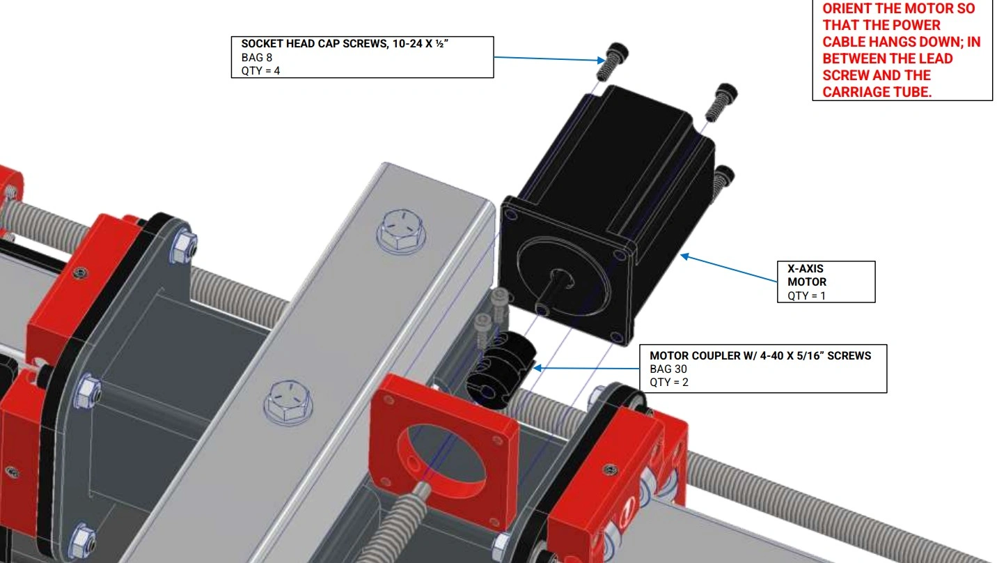
- (1) X-Axis Motor
Hardware
- (4) Bag 8 SOCKET HEAD CAP SCREW, 10-24 X 1/2"
- (1) Bag 30 MOTOR COUPLER
Tools
- 5/32" Hex Key
- 3/32" Hex Key
- 3mm Hex Key
Instructions
- Slide the Bag 30 Motor Coupler onto the end of the X-Axis Lead Screw until it rests against the shoulder.
- Secure the X-Axis Motor to the X-Axis Motor Mount using the fasteners shown and fully tighten. The X-Axis Motor is identical to the Y-Axis Motor with the short cable. NOTE: The motor cable should be oriented downward.
- Tighten the Motor Coupler clamp until the set screws are loosely clamping both the motor shaft and the lead screw stub. The Motor Couplers will be fully tightened in a later step.
13: Install Frame Reinforcements
Install the corner gussets onto the long sides of the machine frame.
Materials
Parts
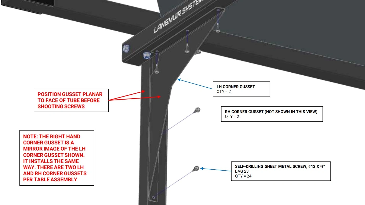
- (2) Left Hand Corner Gusset
- (2) Right Hand Corner Gusset
Hardware
- (24) Bag 23 SELF-DRILLING SHEET METAL SCREW, #12 x 3/4"
Tools
- Drill Gun w/ 5/16" Socket
Instructions
- Position the LH Corner Gusset as shown. Note that the face of the LH Corner Gusset should be flush with the face of the Leg Tube.
- Attach the LH Corner Gusset using the Bag 23 Self-Drilling Sheet Metal Screws using a drill gun.
- Repeat Steps 1 and 2 for the remaining LH Corner Gusset and the two remaining RH Corner Gussets. Make sure to use the correct Corner Gusset in each corner.
Materials
Parts
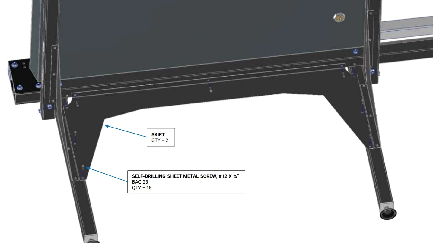
- (2) Side Skirt
Hardware
- (18) Bag 23 SELF-DRILLING SHEET METAL SCREW, #12 x 3/4"
Tools
- Drill Gun w/ 5/16" Socket
- (2) 9/16" Wrench
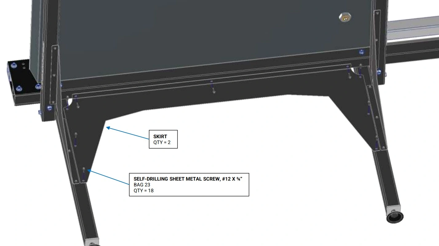
Instructions
- Attach the Side Skirt as shown from the underside of the machine using the Bag 23 Self-Drilling Sheet Metal Screws.
- Repeat Step 1 for the other side.
- Tighten the bolts that secure the leg tubes to the frame.
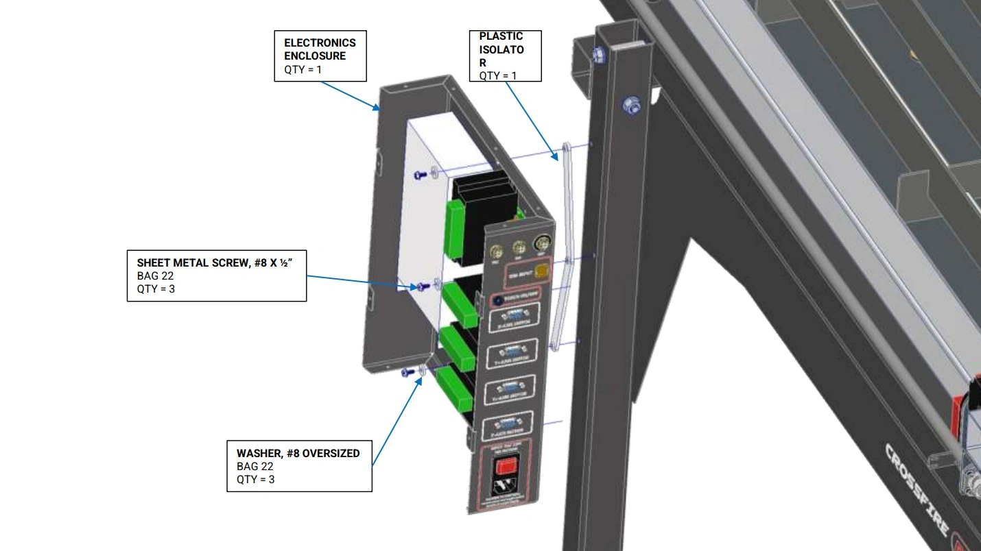
14: Attach Electronics Enclosure
Install electronics enclosure to the mounting holes on the machine frame.
Materials
Parts
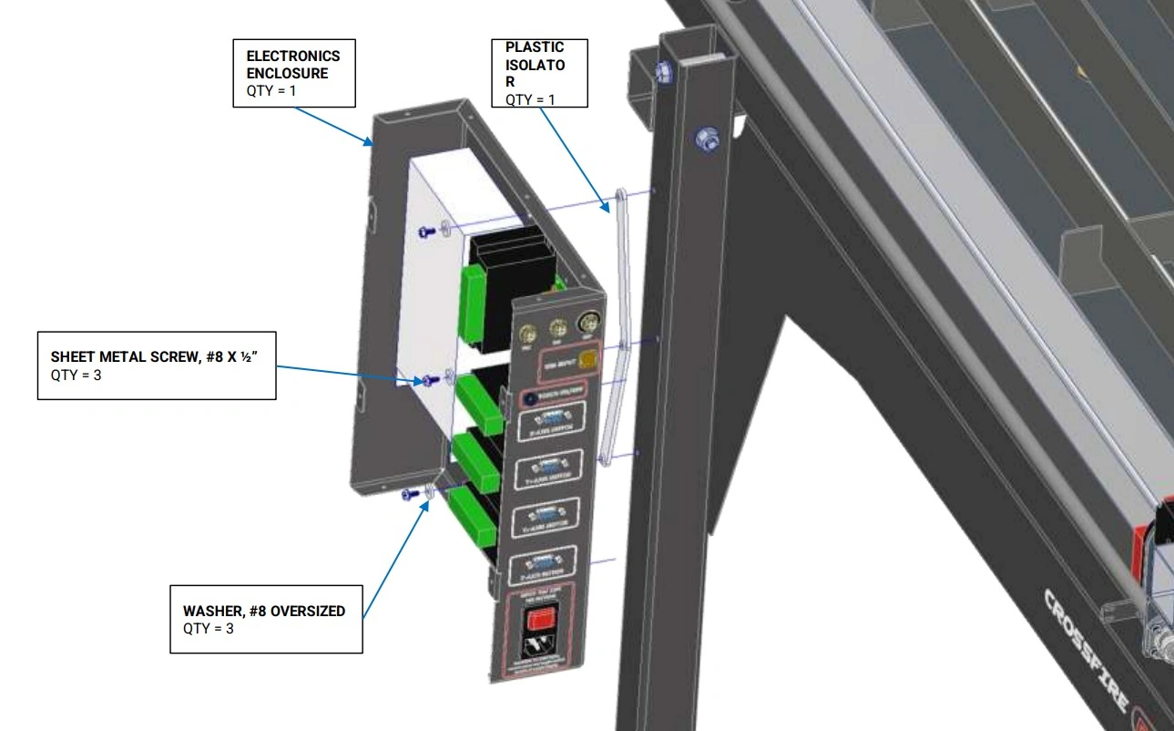
- (1) Electronics Enclosure
Hardware
- (3) Bag 22 SHEET METAL SCREW, #8 X 3/4"
- (3) Bag 22 WASHER, #8 Plastic"
Tools
- 1/4” socket
- Flat head screwdriver
Instructions
- Remove the sheet metal screws that secure the Electronics Enclosure Cover. Set them aside as they will be reused.
- Attach the Electronics Enclosure to the back left Leg Tube using the Bag 22 Sheet Metal Screws and Washers shown. NOTE: There are pre-drilled holes in the leg for the screws to be screwed into.
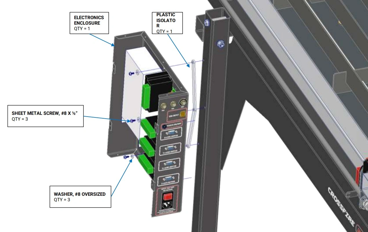
If your hardware box contains a plastic isolator as shown below, please follow the below instructions for this step.
Instructions
- Remove the sheet metal screws that secure the Electronics Enclosure Cover. Set them aside as they will be reused.
- If your Electronics Enclosure mounting holes contain rubber grommets and you also received a plastic isolator- remove the rubber grommets.
- Position the Plastic Isolator in between the electronics enclosure and leg. The Plastic Isolator shall be oriented so that the bosses fit into the holes in the Electronics Enclosure.
- Attach the Electronics Enclosure to the back left Leg Tube using the Bag 22 Sheet Metal Screws and Washers shown. NOTE: There are pre-drilled holes in the leg for the screws to be screwed into.
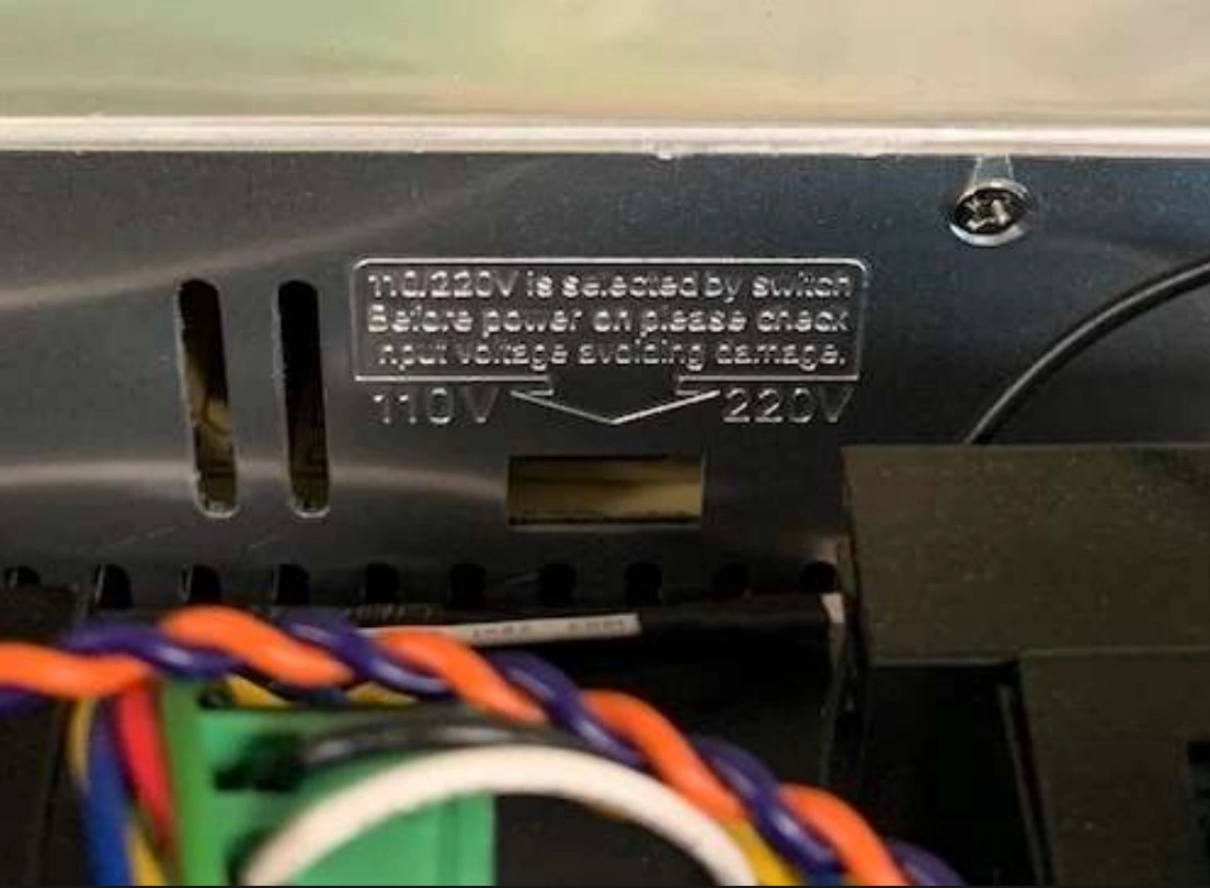
Materials
If you are using the CrossFire or CrossFire ProMAX in a region with 220V power, be sure to flip the switch on the power supply to avoid damaging the power supply and other CrossFire electronics. It is set to 110V by default.
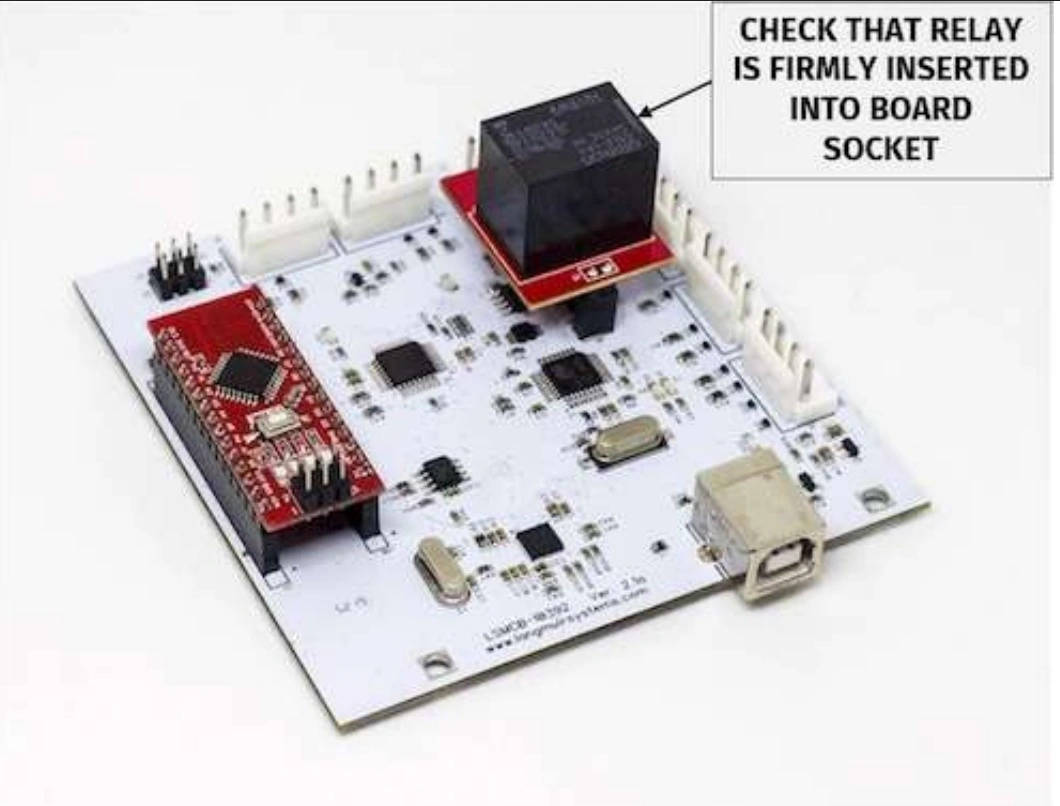
Ensure Installation of Replaceable Relay
While the electronics enclosure is open, make sure that the torch firing relay (marked in image below) is properly seated.

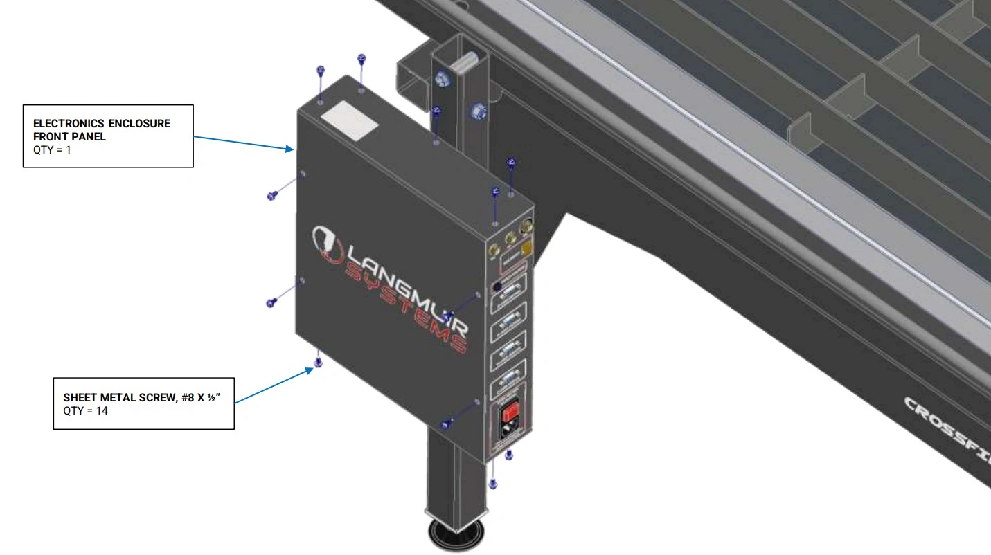
Instructions
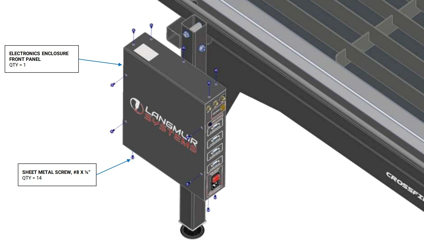
- Re-attach the Electronics Enclosure Cover with Sheet Metal Screws that were originally installed.
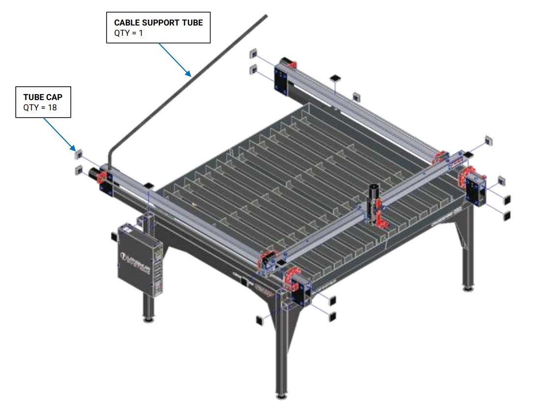
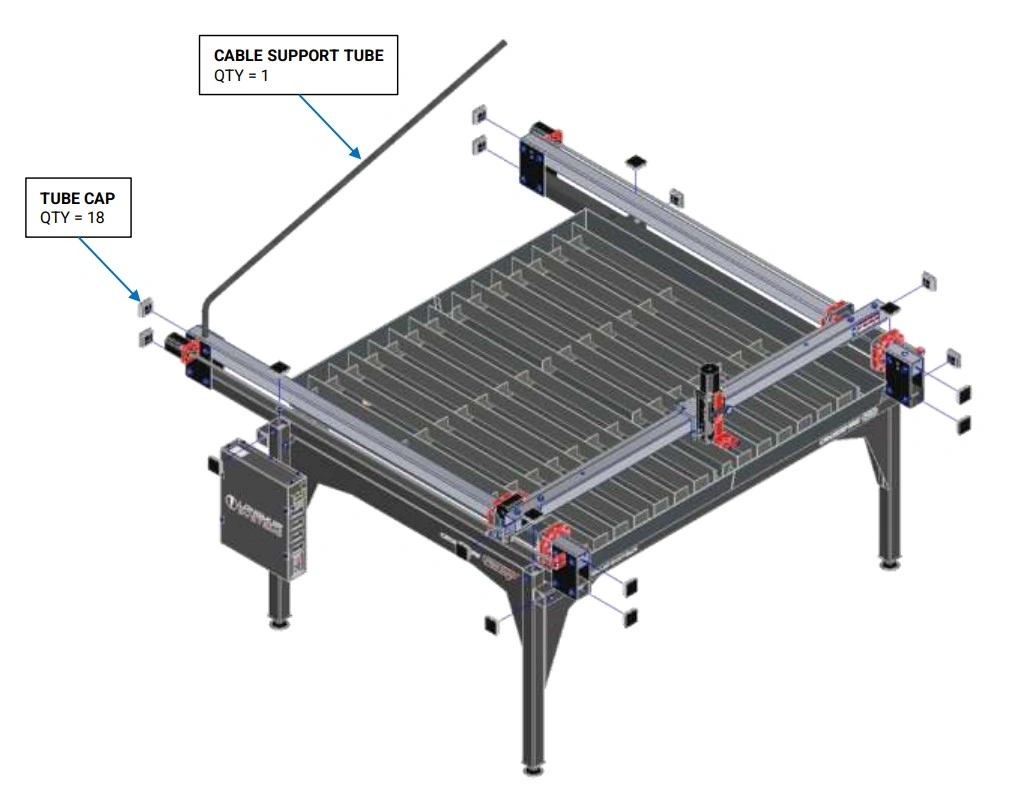
15: Install Caps and Cable Support Tube
Finish assembly of the CrossFire ProMAX.
Materials
Parts
- (18) Tube Cap
- (1) Cable Support Tube
Hardware
- None
Tools
- Mallet
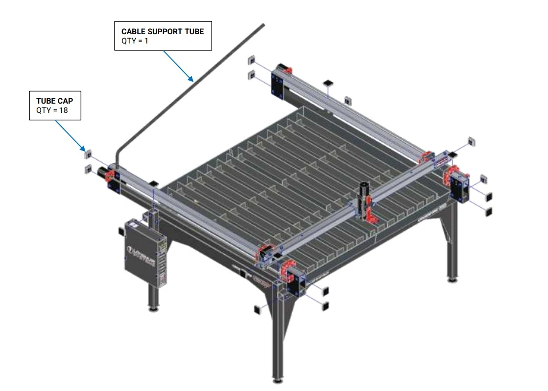
Instructions
- Using a mallet, insert Tube Plugs into the open ends of each tube.
- Insert the Cable Support Tube into the left hand Y-Axis Rail cable support hole.
16: Laptop Stand Assembly
Install the mounting bracket on front left stanchion plate bolts along with the vertical support and the tray.
Materials
Parts
- (1) Tray
- (1) Vertical Support
- (1) Mounting Bracket
Hardware
- (4) Laptop Stand HW Flathead Screw, 10-32 x ½"
- (4) Laptop Stand HW Washer, #10
- (4) Laptop Stand HW Locknut, 10-32
- (2) Laptop Stand HW Socket Head Cap Screw, ¼-20 x ½"
- (2) Laptop Stand HW Washer, ¼"
- (2) Laptop Stand HW Serrated Flange Nut, ¼-20
Tools
- Phillips Head Screwdriver
- 3/8 Wrench
- 7/16" Wrench
- 3/16" Hex Key
- 9/16" Wrench
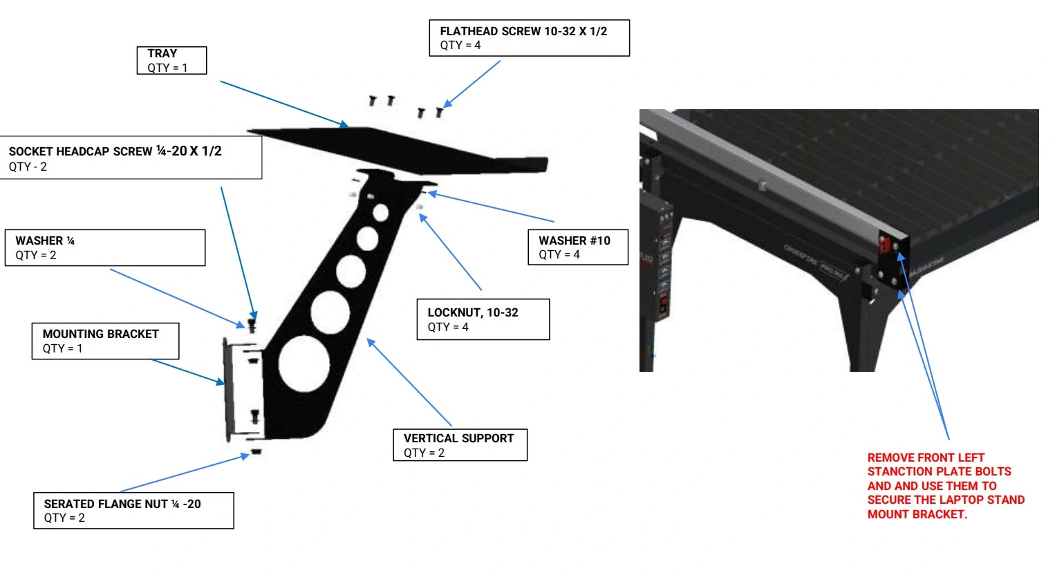
Instructions
- Secure the Tray to the Vertical Support using the Laptop Stand Hardware depicted.
- Secure the Vertical Support to the Mounting Bracket using the hardware depicted. The screws can be left slightly loose if swivel capability is desired.
- Attach this Laptop Stand Assembly to the front left corner of the machine using the Stanchion Plate bolts as shown in the image on the right.
17: Monitor Stand Assembly
Install the mounting bracket on front left stanchion plate bolts along with the vertical support, monitor brackets and the monitor.
Materials
Parts
- (1) Pivot Bracket
- (1) Vertical Support
- (1) Mounting Bracket
Hardware
- (6) Monitor Stand HW Socket Head Cap Screw, ¼-20 x ½"
- (6) Monitor Stand HW Washer, ¼"
- (6) Monitor Stand HW Serrated Flange Nut, ¼-20
Tools
- 7/16" Wrench
- 3/16" Hex Key
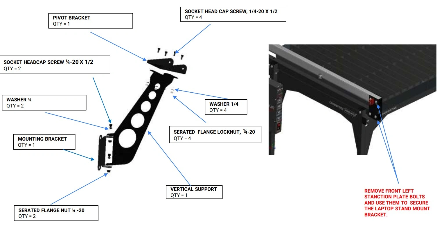
Instructions
- Secure the Vertical Support to the Mounting Bracket using the hardware depicted. The screws can be left slightly loose if swivel capability is desired.
- Secure the Pivot bracket to the vertical support using the hardware depicted.
- Attach this Monitor Stand Assembly to the front left corner of the machine using the Stanchion Plate bolts as shown in the image on the right.
- This completes the Monitor Stand Assembly.
Materials
Parts
- (1) Monitor
- (1) VESA Mount
- (1) PC Bracket
- (1) PC
Hardware
- (4) Socket Head Cap Screw, M3 x 0.5 x 6 mm
- (4) Socket Head Cap Screw, M4 x 0.7 x 6 mm
- (2) Hex Nut, M3 x 0.5
Tools
- Metric Allen Key Set
- 2.5 mm Allen Key
- 3 mm Allen Key
- Small Wrench or Nut Driver
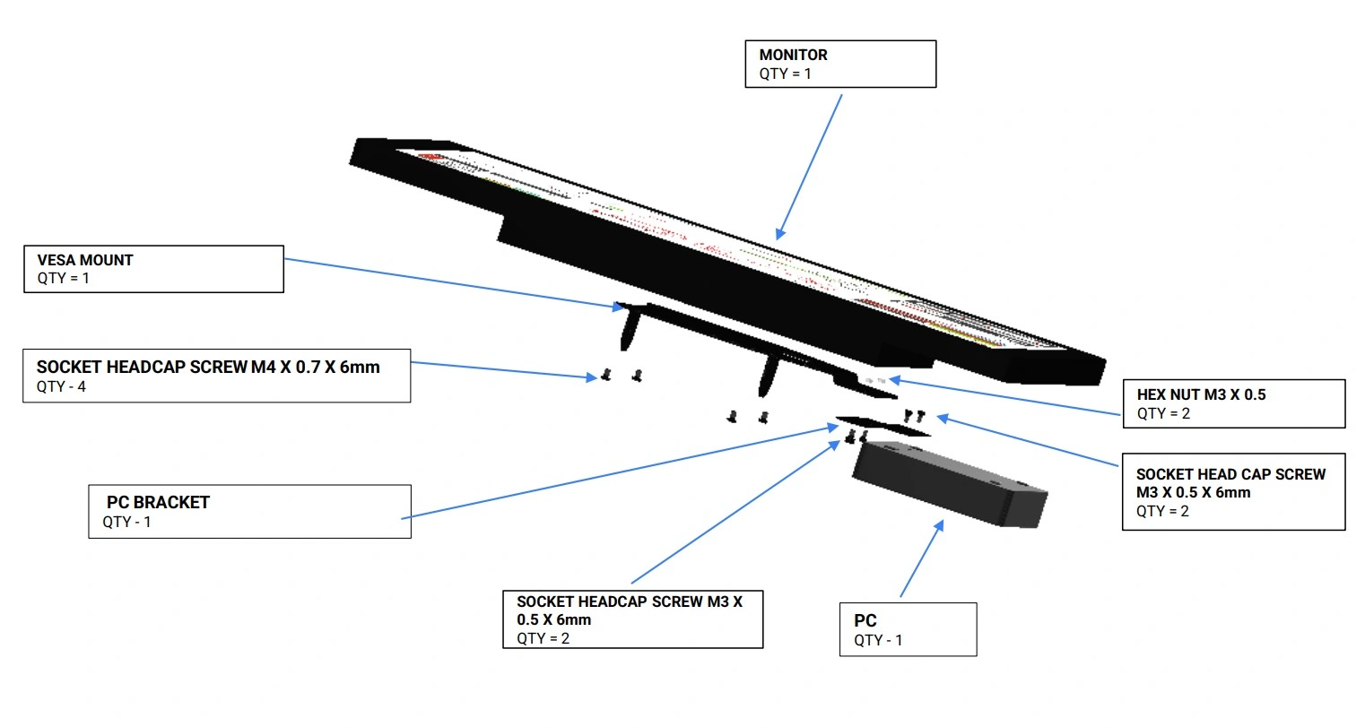
Instructions
- Secure the Vesa Mount to the Monitor using the hardware depicted.
- Secure the PC mount to the Vesa mount using the hardware depicted.
- Secure the PC to the mount using the hardware depicted.
- This completes the Monitor assembly.
Materials
Parts
- (1) Monitor Assembly
- (1) Monitor Stand Assembly
Hardware
- (2) Socket Headcap Screw, 1/4-20 x 1/2"
- (2) Washer, 1/4"
- (2) Locknut, 1/4-20
Tools
- 3/16" Hex Key
- 7/16" Wrench
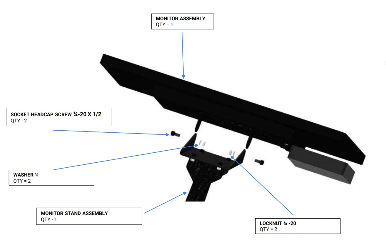
Instructions
- Secure the Monitor stand assembly to the Monitor Assembly using the hardware depicted. The screws can be left slightly loose if swivel capability is desired.
Crossfire Pro to ProMax Upgrade Assembly Instructions
Images in this Guide
The assembly drawings and pictures included in this guide can be expanded to full-screen and zoomed to provide more detail on a given step.
1: Make the Crossfire Pro Safe
We need to prepare the Crossfire Pro to safely disassemble and install the upgrade kit.
Materials
Parts
- None
Hardware
- None
Tools
- (1) 3/16” Allen Wrench
- (1) ⅜” Combination Wrench or Adjustable Wrench
- (2) 9/16” Wrench
- (1) Funnel, bucket and hose
Instructions
- Disconnect power, ensure machine is turned off and power cable is unplugged and removed from the electronics module.
- Using the 3/16” Allen Wrench, remove plasma cutter hand torch or the machine torch depending on your setup.
- Using (2) 9/16” wrenches, remove the laptop stand, if equipped.
- Remove the slats and slat holders.
- Using the ⅜” wrench or combination wrench, drain and clean the water table.
- The Crossfire Pro holds 16 gallons of water. Have preparation to contain 20 gallons of water.
- Be prepared to use a funnel, hose and bucket to contain the water from the water table.
- Cleaning needs to be performed to gain access to the mounting screw heads for the water table. Cleaning the table reduces the possibility of water and cutting debris to soil the shop in later steps.
2: Remove the Cable Support Tube
Removal of the cable support tube to allow for gantry removal.
Materials
Parts
- None
Hardware
- None
Tools
- Flat Head Screwdriver or Mini Pry Bar
Instructions
- Remove the velcro tabs used to secure the motor cable to the cable support tube.
- Remove the cable support tube by pulling it out of its hole.
- Using the flat head screwdriver or mini pry bar, remove the eight (8) square plastic tube caps on the Y-Axis upper and lower rails in the front and rear of the machine and set aside for re-instalation after the upgrade is complete.
3: Remove the electronics enclosure
Removal of the electronics enclosure
Materials
Parts
- None
Hardware
- None
Tools
- (1) 1/4” Socket, Ratchet and 3” extension
- (1) Flat head screwdriver (optional)
- (1) Screw gun (optional)
Instructions
- Remove the P-clamps securing the Y2 stepper motor. Set these screws and P-clamps aside as we will be reusing them in a later step.
- Using the ¼” socket or screwdriver, remove the fourteen (14) screws securing the electronics enclosure cover to the electronics enclosure. Set these screws aside as we will be reusing them in a later step.
Materials
Parts
- None
Hardware
- None
Tools
- (1) 1/4” Socket, Ratchet and 3” extension
- (1) Flat head screwdriver (optional)
- (1) Screw gun (optional)
Instructions
- Using the ¼” socket or screwdriver, remove the three (3) screws securing the electronics enclosure to the leg of the Crossfire. Set these screws and plastic isolator aside as we will be reusing them in a later step.
- Set the enclosure near the leg taking care not to over extend any wires.
NOTE
It is recommended to disconnect the motors and other components from the enclosure. If you choose not to disconnect components from the enclosure, it is recommended to keep the enclosure close to the machine to prevent damage from overextending cables.
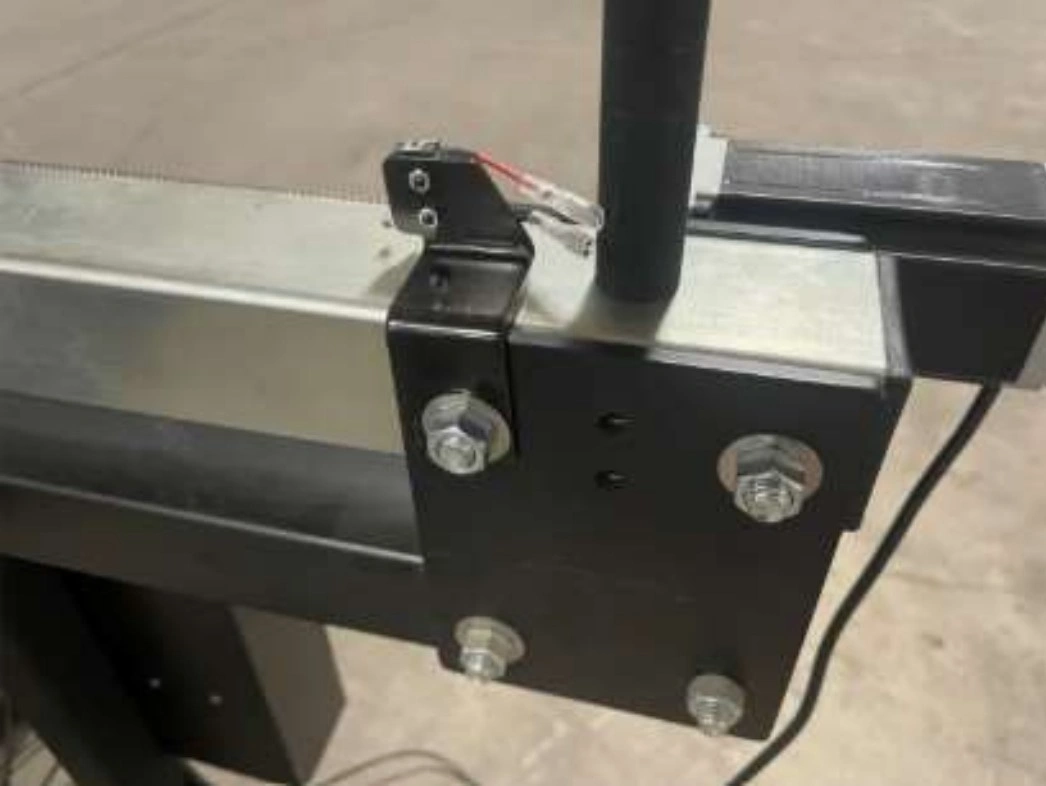
4: Removal of the Y-Axis Limit Switch
Removal of the Y-Axis limit switch for tube replacement if your machine has the limit switch package installed.
Materials
Parts
- None
Hardware
- None
Tools
- (2) 9/16” Wrench
Instructions
- Using the9/16” wrenches, remove the bolt in the stanchion plate that securs the Y-Axis limit switch.
- Place the limit switch and bracket next to the electronics enclosure.
- Retain the ⅜” hardware as we will be using them in future steps.
5: Removal of the Y-Axis Lead Screw
The next step in the assembly process is to remove the Y-Axis lead screw.
Materials
Parts
- None
Hardware
- None
Tools
- (1) 9/64” Allen Wrench
- (1) 11/32” Wrench
Instructions
- Remove the four (4) #8-32 x ¾” socket head cap screw, four (4) #8-32 lock nut and sixteen (16) washers from the LH Y-Axis carriage. Set these aside as we will be reusing this hardware.
- Repeat this process for the RH Y-Axis carriage.
Materials
Parts
- None
Hardware
- None
Tools
- (1) 5/32” Allen Wrench
- (1) 3/32” Allen Wrench
- (1) 3/16” Allen Wrench
Instructions
- Remove the #10-32 x ⅜” socket head cap screw and #10 washer from the LH Y-Axis lead screw. Set Aside for use when installing the new lead screw.
- Loosen the two (2) screws on the motor coupler securing the lead screw to the motor. The coupler should still be attached to the motor.
- Remove the two (2) ¼-20 x ¾” socket head cap screws securing the motor mount (with motor attached) to the stancion plate. Set the motor near the electronics enclosure. Set the hardware aside for reinstalling the motor mounting plate.
- Remove the two (2) ¼-20 x ¾” socket head cap screws securing the lead screw bearing mount (with bearing attached) to the stancion plate. Set the lead screw bearing mount and the hardware aside for reinstalling the bearing mounting plate.
- The lead screw assembly can now be removed.
- Repeat the above steps for the RH lead screw.
6: Gantry and Y-Axis Tube Removal
The next step is to remove the gantry assembly for rail replacement.
Materials
Parts
- None
Hardware
- None
Tools
- (1) ⅛” Allen Wrench
- (1) 3/16” Allen Wrench
Instructions
NOTE
These instructions are written to remove the gantry assembly from the back of the Crossfire Pro. If you choose to remove the gantry from the front of the machine, loosely reinstall the ⅜” bolt removed in Step 4 to help support the assembly when removing it from the Crossfire.
- Loosen the screws securing the adjustable bearing blocks to the backing plate.
- Release bearing preload on the Y-Axis bearing blocks by turning the adjustment set screw two (2) turns counter clockwise.
- Repeat for the other three (3) bearing block assemblies on the Y-Axis rails.
Materials
Parts
- None
Hardware
- None
Tools
- (2) 9/16” Wrenches
Instructions
NOTE
These instructions are written to remove the gantry assembly from the back of the Crossfire Pro. If you choose to remove the gantry from the front of the machine, loosely reinstall the ⅜” bolt removed in Step 4 to help support the assembly when removing it from the Crossfire.
- Move the gantry to the rear of the Crossfire Pro.
- Completely remove one (1) upper and one (1) lower bolt from the RH and LH stancion plates on the rear of the Crossfire Pro.
- Loosen and remove the nuts from the remaining upper and lower bolts on the rear stanchion plates.
- While supporting the gantry assembly, remove the remaining hardware and stanchion plates from both sides of the machine and slide the gantry assembly off of the Y-Axis tubes.
- It is recommended to place the stanchion plates and hardware into the water table to minimize the stress on the tubes from an unsupported gantry.
- Set the gantry assembly aside as it will be reused. If the motors were not disconnected from the electronics enclosure, set the gantry assembly near the electronics enclosure.
- Remove the remaining stanchion plates from the Y-Axis tubes.
- Collect the ⅜” bolts, washers and nuts and set aside for use when reinstalling the new Y-Axis tubes.
- The stanchion plates will not be re-used for the ProMAX upgrade. They can be placed with the lead screws in the old parts area.
7: Remove the water table
The next step in the upgrade process is to remove the water table
Materials
Parts
- None
Hardware
- None
Tools
- (1) ¼” Wrench or ¼” Nut Driver and Drill
Instructions
- Remove the twelve (12) self tapping screws holding the water table to the frame.
- Remove the water table from the frame and set aside.
8: Replace the Lower Frame Rails
The next step is to remove and replace the lower frame rails.
Materials
Parts
- (1) Y-AXIS LOWER RAIL TUBE, LH
- (1) Y-AXIS LOWER RAIL TUBE, RH
Hardware
- Re-use Removed Hardware
- (12) Tube Spacer
- (4) ⅜”-16 x 4.5 Hex Head Cap Screw
- (4) ⅜”-16 x 2.5 Hex Head Cap Screw
- (8) ⅜”-16 Hex Nut
Tools
- (2) 9/16 Wrench
- (1) 5/16” Socket or Wrench
- (1) Powered Driver Optional
Instructions
- Remove the three (3) screws holding the side skirt onto the lower LH Y-Axis frame rail. Retain this hardware for re-instalation.
- Remove the three (3) screws holding the side skirt onto the lower RH Y-Axis frame rail. Retain this hardware for re-instalation.
- Remove the lower LH rail and replace with new lower LH rail part number LS-PRO4-1001.
- We will be reusing the hardware and tube spacers.
- The front of the Crossfire will be bolted together and tight. This will increase the stability the assembly and reduce the resquaring possibilities.
- The rear leg placement will be farther behind the current location. This location will be corrected in a later step.
- Repeat step A3 for the RH Lower Rail.
- Remove the six (6) screws holding the rear legs to the side skirt and install the rear legs in the closest set of holes to the front of the Crossfire.
- Reuse the hardware and tube spacers from steps A3 and A4.
- Remove the final 6 screws holding the side skirts to the front legs and place the side skirts aside.
Materials
Parts
- Hand Tightened Frame Assembly
Hardware
- None
Tools
- (1) Tape Measure
- (2) 9/16” Wrench
- (1) Soft Faced Hammer or Mallet
- (1) Protractor, Carpenters Square or Machinist Square
Instructions
- Using a protractor, carpenter’s square, or combination square, make the Lower Rail Tubes perpendicular to the Lower Cross Tubes.
- Using a tape measure, measure the distance between the LH and RH Lower Rails at each end (Distance ‘A’ and Distance ‘B’). If the two measurements are different by more than 1/32”, lightly tap on one of the lower rails to equalize the spans.
- Carefully tighten the bolts that connect the LH Lower Rail and RH Lower Rail to the Lower Cross Tubes.
- Double check that the LH and RH Lower Rails are still parallel within 1/32” after tightening. If they are not, repeat steps 1 and 2.
- Seat the bolts that secure the legs to the Frame, but DO NOT tighten them at this step. The goal is to simply take up the slack in the joint. The legs will be wobbly at this step which is OK. The leg bolts will be tightened at a later step.
9: Install the Gantry Assembly
The gantry gets re-installed on the new upper Y-Axis rails.
Materials
Parts
- (8) Stanchion Plate
Hardware
- Re-use Removed Hardware
- (16) ⅜”-16 x 3 Hex Head Cap Screw
- (16) ⅜”-16 Hex Nut
- (32) ⅜” Washer
Tools
- (2) 9/16” Wrench
Instructions
- Insert one Y-Axis Rail into each of the Y-Axis Carriage assemblies. The orientation of each Y-Axis Rail is important and must match what is shown in the diagrams.
- Secure the Y-Axis rails to the Gantry by Installing the Stancion Plates onto the rail once the Y-Axis rail is inserted as shown in the image above.
- The upper set of holes are to be used as the gantry will sit higher to accommodate the new water table.
- Secure the Y-Axis Rails to the machine frame assembly using the Stanchion Plates and fasteners shown. Make sure that ¼” diameter holes in the Y-Axis Rail line up to the holes in the Stanchion Plates. If they do not line up, then the Y-Axis Rail is likely installed upside down.
- Tighten each of the bolts that secures the stanchion plates to both lower rail tubes. DO NOT tighten the bolts that secure the stanchion plates to the Y Axis Rails. They will be tightened in a later step.
NOTE
The carriage bearings should be loose on the rails. They will be pre-loaded in a later step.
10: Y-Axis Adjustment
Each Y-Axis Carriage Assembly includes two (2) Bearing Block Assemblies. Each Bearing Block Assembly contains four bearing blocks; two (2) are fixed and two (2) are adjustable. The goal of this step is to adjust the Adjustable bearing Block to ensure that the bearings are properly preloaded into the Y-Axis Rails.
Materials
Parts
- Gantry Assembly Mounted on Crossfire
Hardware
- None (Pre-Installed)
Tools
- (1) 3/16” Allen Wrench
- (1) ⅛” Allen Wrench

Instructions
- On each Adjustable Bearing Block, seat both socket head cap screws and then back them off approximately 1/4 turn. Next, slowly turn the adjustment set screw clockwise. Stop turning the set screw when at least one of the two opposing Fixed Bearing Block Bearings is in contact with the rail and when no play can be felt.
- Once Step A2 is complete, tighten the socket head cap screws that secure the Adjustable Bearing Block to the backing plate.
- Complete Steps A2 and A3 for each of the eight Adjustable Bearing Blocks that the machine has.
Materials
Parts
- (1) Assembled Machine Gantry
Hardware
- None
Tools
- (2) 9/16” Wrench
- 3/16” Allen Wrench
- 7/16” Wrench
Instructions
- Slide the Gantry Assembly along the Y-Axis Rails until the bearings touch the Stanchion Plates as shown.
- Tighten the 16 cap screws that secure the Fixed Bearing Block Assemblies to the Y-Axis Carriages.
- Tighten the 8 bolts that secure the Y Axis Rails to the Stanchion Plates that were left loose in a previous step.
- Cycle the Gantry Assembly back and forth along the Y-Axis Rails to make sure that it moves freely. If it does not, repeat previous steps to make the Y-Axis Rails parallel.
- Verify there is no lash/play between the rolling carriages and the rails. If there is, repeat Step 3 of the previous instruction set to further pre-load the adjustable.
11: Join & Install Water Table
Join both halves of the water table.
Materials
Parts
- (2) Water Table Half Section
Hardware
- (1) Silicone Sealant
Tools
- None
Instructions
- Thoroughly clean the flange face of each Water Table Half Section. Before proceeding, make sure that you plan to join the water tables within 5 minutes after applying the silicone adhesive.
- On one of the Water Table Half Sections, apply a uniform bead of Silicone Sealant (provided) approximately ¼” in diameter along the path shown.
- Apply a bead of silicone to the inside of each of the four welded corners
Materials
Parts
- Water Table Section Halves prepared with Silicone
Hardware
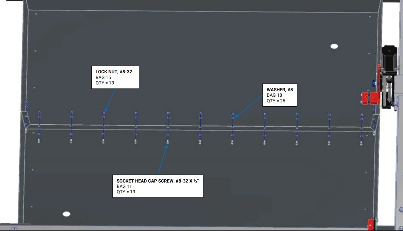
- (13) SOCKET HEAD CAP SCREW, 8-32 X 1/2"
- (26) WASHER, #8
- (13) LOCK NUT, #8-32
Tools
- 9/64" Allen Wrench
- 11/32" Wrench
Instructions
- Place both Water Table Half Sections onto the machine frame with a gap between the two.
- Carefully squeeze the flanges together and install all fasteners as shown. Tighten the fasteners to a medium level of tightness. It is extremely important that the bottom of the water tables are even with each other before fully tightening the screws. Wipe away any squeezed out Silicone Sealant. Allow to cure for 24 hours before filling with water.
Materials
Parts
- (2) Brass Drain Plug
- (1) Water Table (joined)
- (1) Machine Frame
Hardware
- (16) SELF-DRILLING, SEALING SHEET METAL SCREW, #10 x 3/4”
- (2) THIN NUT, 1”-8
- (2) O-RING
- (2) PIPE PLUG, ¼” NPT
Tools
- (1) Drill with 5/16” socket
- (1) Tape Measure
- (1) 5/16” Wrench
Instructions
- Use a tape measure to center the Water Table in both directions on the machine frame. It is critical that the amount that the Water Table overhangs the Lower Cross Tubes is equal on the front and the back.
- With the Water Table properly positioned, install the #10 x 3/4 Self-Drilling Sealing Sheet Metal Screws through the holes in the Water Table into the Lower Cross Tubes using a drill. Clear any chips out to ensure a water tight seal.
- For each Drain Plug Assembly (2), slide the O-Ring onto the outer diameter of the Brass Drain Plug. Insert the Brass Drain Plug into the hole in the Water Table. Reach underneath the Water Table and screw the Thin Nut onto the Brass Drain Plug and hand tighten. Screw the Pipe Plug into the Brass Drain Plug.
12: Install Slats
Install the slats and slat holders on the Crossfire.
Materials
Parts
- (14) Slats
- (8) Slat Holders
- (4) Water Table Slat TP
- (1) Water Table
Hardware
- None
Tools
- (1) Mallet

Instructions
- Place the four Water Table Slat TPs at the bottom of the Water Table such that they cover up the previously installed sheet metal screws.
- Insert the Slats into the slots of the Slat Holders. Tap them in with a mallet as needed to fully seat them.
13: Install Motor Mounts & Lead Nuts
Install the mounts for the Y-Axis Stepper Motors.
Materials
Parts
- (2) Y-Axis Motor Mount With Motor
Hardware
- None
Tools
- (1) 3/16” Allen Wrench
Instructions
NOTE
Identify the Y1 and Y2 motors by motor position and cable length. Place the motors on the appropriate side of the Crossfire so the motor cables can reach to the electronics enclosure mounting location.
- Remove the four (4) 10-24 x ½ socket head screws that attach the Y-Axis Motor to the Y-Axis Motor Mount.
- Secure the Y-Axis Motor Mount to the left hand Y-Axis Rail using the ¼-20 x ¾ Socket Head Cap Screws, both items were removed earlier, and hand tighten only.
NOTEThe screws have to be inserted through the mounting holes inside of the Y-Axis Rail Tube. Temporarily removing the ⅜” Stanchion Plate bolts makes it easier to install the screws. Replace the ⅜” Stanchion Plate bolt when complete.
- Repeat Steps A1 and A2 for the other side.
Materials
Parts
- (2) Y-Axis Carriage (on assembled machine)
Hardware
- (4) SOCKET HEAD CAP SCREW, #8-32 X 3/4"
- (16) #8 WASHER
- (8) LOCK NUT, #8-32
- (2) Y-AXIS LEAD NUT
Tools
- (1) 9/64" Allen Wrench
- (1) 11/32" Wrench
Instructions
- Secure the Y-Axis Lead Nut to the lefthand Y-Axis Carriage using the fasteners shown. Do not fully tighten the screws; the Y-Axis Lead Nut must be able to float in all directions for alignment in a later step.
- Repeat Step 1 for the other side.
Materials
Parts
- (2) Y-Axis Lead Screw Bearing Mount
Hardware
- (4) SOCKET HEAD CAP SCREW, 1/4-20 X 3/4"
Tools
- 9/64" Allen Wrench
- 3/16" Allen Wrench
Instructions
- The bearings should still be installed but if they are not, two (2) 8-32 x ½ socket head cap screws are used.
- Secure the Y-Axis Lead Screw Bearing Mount to the left hand Y-Axis Rail using the two (2) ¼-20 x ¾ Socket Head Cap Screws and hand tighten only. NOTE: the screws have to be inserted through the mounting holes inside of the Y-Axis Rail Tube. Temporarily removing the ⅜” Stanchion Plate bolt makes it easier to install the screws. Replace the ⅜” stanchion plate bolt when complete.
- Repeat Steps 1 and 2 for the other side.
14: Install Lead Screws
Install both of the Y-Axis Lead Screws.
Materials
Parts
- (2) Y-Axis Lead Screw (3/8")
- (2) Y-Axis Lead Nut (previously installed)
Hardware
- (2) SOCKET HEAD CAP SCREW, 10-32 X 3/8"
- (2) #10 WASHER
Tools
- (1) 5/32" Allen Wrench
Instructions
- Position the Gantry in approximately the center of its travel.
- Starting with the end of the that has the tapped hole, screw the Y-Axis Lead Screw into the Y-Axis Lead Nut (make sure to pull back on the White Compression Collar during initial insertion of the lead screw to prevent damage to the lead nut). Continue turning the Y-Axis Lead Screw until it can fit into the bearing that is mounted in the Y-Axis Lead Screw Bearing Mount.
- Secure the lead screw to the bearing using the hardware shown and fully tighten.
- Repeat Steps A2 and A3 for the other side.
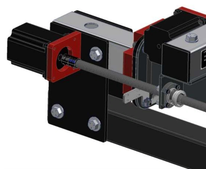
15: Install Motors
Install the Y1 and Y2 motors on the Crossfire.
Materials
Parts
- (1) Y-Axis Motor (short cable)
- (1) Y-Axis Motor (long cable)
Hardware
- (8) SOCKET HEAD CAP SCREW, 10-24 X 1/2"
- (2) MOTOR COUPLER
Tools
- (1) 5/32" Allen Wrench
- (1) 3/32" Allen Wrench
- (1) 3mm Allen Wrench

Instructions
- Loosen the two (2) remaining 4-40 x 5/16 screws in the Motor Coupler to allow the motor coupler to slide all of the way to the motor.
- Secure the Y-Axis Motor with the short cable to the Y-Axis Motor Mount using the fasteners shown (removed in a previous step) and fully tighten. NOTE: The motor cable should be oriented downward.
- Do not tighten the Motor Coupler clamp. They will be tightened in a later step.
- Tighten the screws that secure the Y-Axis Motor Mount and the Y-Axis Lead Screw Bearing Mount to the Y-Axis Rail Tube.
- Slide the motor coupler to the shoulder of the Y-Axis Lead Screw and tighten the Motor Coupler clamp until the set screws are loosely clamping both the motor shaft and the lead screw stub. The Motor Couplers will be fully tightened in a later step.
- Repeat Steps A1 through A5 for the other side using the Y-Axis Motor with the long cable.
16: Install Frame Reinforcements
Install the frame skirting.
Materials
Parts
- (2) Side Skirt
Hardware
- (18) SELF-DRILLING SHEET METAL SCREW, #12 x 3/4"
Tools
- (1) Drill with 5/16" Socket
- (2) 9/16" Wrench
Instructions
- Attach the Side Skirt as shown from the underside of the machine using the #12 x ¾ Self-Drilling Sheet Metal Screws.
- Repeat Step 1 for the other side.
- Tighten the bolts that secure the leg tubes to the frame.
17: Attach Electronics Enclosure
Install electronics enclosure to the mounting holes in the machine frame.
Materials
Parts
- (1) Electronics Enclosure
Hardware
- (3) SHEET METAL SCREW, #8 X 3/4"
Tools
- (1) 1/4” Wrench or Flat head screwdriver
Instructions
- Position the Plastic Isolator in between the electronics enclosure and leg. The Plastic Isolator shall be oriented so that the bosses fit into the holes in the Electronics Enclosure.
- Attach the Electronics Enclosure to the back left Leg Tube using the #8 x ½ Sheet Metal Screws and Washers shown (removed in the first step). NOTE: There are pre-drilled holes in the leg for the screws to be screwed into.
Materials
Parts
- (1) Electronics Enclosure Cover
Hardware
- (14) SHEET METAL SCREW, #8 X 3/4"
Tools
- (1) 1/4” Wrench or Flat head screwdriver
Instructions
- Re-attach the Electronics Enclosure Cover with Sheet Metal Screws that were originally installed.
18: Install Caps & Cable Support Tube
Finish assembly of the Crossfire ProMAX.
Materials
Parts
- (18) Tube Cap (Removed in step 2)
- (1) Cable Support Tube (removed in step 2)
Hardware
- None
Tools
- Mallet
Instructions
- Using a mallet, insert Tube Plugs that were set aside into the open ends of each tube.
- Insert the Cable Support Tube into the left hand Y-Axis Rail cable support hole.
- Finish securing the motor cables to the support arm.